Page is loading ...

Installation Manual
355 Lighting System
Go To Table Of Contents
230 Volt Models
Style F
Go To Table Of Contents

Owner's Product Identification
(information that you'll need to provide for servicing - key information is highlighted)
Date of Purchase
Serial Number(s) - Dual light systems will have a
serial number on each down tube
Model Number
Name of Authorized Dealer Telephone # of Authorized Dealer
Address of Authorized Dealer
Name of Owner/Facility/Department
MA547100
MODEL AND
SERIAL NUMBER
Go To Table Of Contents

Table of Contents
IMPORTANT INFORMATION
Scope And Purpose Of This Manual .............................................. 2
Safety Instructions .......................................................................... 2
Safety Symbols and Notes ............................................................. 2
Transportation and Storage Conditions .......................................... 3
GENERAL INFORMATION
Lighting System .............................................................................. 3
Specifications ................................................................................. 3
Range of Motion ............................................................................. 4
355 LIGHTING SYSTEM INSTALLATION
Unpacking....................................................................................... 5
Recommended Ceiling Mounting Locations (For Dental and
Medical Applications) ............................................................... 6
Ceiling Support Structure Installation ............................................. 6
Electromagnetic Interference.......................................................... 8
Wiring Installation ........................................................................... 8
Junction Box Wiring Connections ................................................... 8
Ceiling Plate Assembly Installation............................................... 11
Down Tube Installation .................................................................. 12
Cross Tube Assembly Installation ................................................. 13
Bulb Installation ............................................................................ 14
Housing Cap Installation............................................................... 15
Operational Test............................................................................ 15
TROUBLESHOOTING
Troubleshooting Guide.................................................................. 16
ADJUSTMENTS
Ball Pivot Joint Tension Adjustment .............................................. 17
Cross Tube Counterbalance Adjustment ...................................... 18
Height and Clearence Dimension ................................................. 19
CALLING FOR SERVICE ....................................................................... 19
LIMITED WARRANTY ............................................................................ 20
Go To Table Of Contents

2
WARNING
A WARNING is used for a potentially
hazardous operating procedure, practice,
or condition which, if not correctly followed,
could result in loss of life or serious personal
injury.
CAUTION
A CAUTION is used for a potentially
hazardous operating procedure, practice, or
condition which, if not correctly followed, could result in
minor or moderate injury. It may also be used to alert
against unsafe practices.
EQUIPMENT ALERT
An EQUIPMENT ALERT is used for an
imminently or potentially hazardous
operatingprocedure, practice, or condition which, if not
correctly followed, will or could result in serious,
moderate, or minor damage to unit.
Note
A NOTE is used to amplify an operating procedure,
practice, or condition.
Indicates that theunit is rated: Type B, Applied
Part.
Indicates a protective earth ground.
Indicates that the operator's manual should be
consulted for important information.
Indicates the product is fragile; do not handle
roughly.
Indicates the proper shipping orientation for the
product.
Indicates the presence of a dangerous voltage /
shock hazard.
Indicates the product must be kept dry.
Indicates a fuse rating specification.
Indicates a hot surface.
IMPORTANT INFORMATION
Scope and Purpose of Manual
This manual covers complete instructions for the
installation of the 355 Lighting System and is intended to
be used by personnel involved in the installation of the
355 Lighting System. The Operation Manual for the 355
Lighting System is a separate document and is intended
for persons who will operate the 355 Lighting System.
Intended Use of Product
This product is intended for use in all medical environ-
ments whrere illumination is required for external exami-
nations and procedures.
Authorized EU Representative
Countries in the EU should direct all questions, incidents
and complaints to Midmark's Authorized EU representa-
tive listed below:
Midmark EMEA Ltd
Beech House, First Floor, East Wing
Ancells Business Park
Fleet
Hampshire, GU51 2UN
United Kingdom
Tel: + 44 (0) 1252 360 940
Fax: + 44 (0) 1252 360 941
Safety Instructions
The primary concern of Midmark is that this equipment be
operated and maintained with the safety of the users in
mind. To assure safer and more reliable operation, do
the following: (1) Read this manual before installing your
light assembly; (2) Assure that appropriate personnel are
informed on the contents of this manual--this is the
responsibility of the purchaser; (3) Be sure that you
understand the instructions contained in this manual
before attempting to install this light assembly; (4) Be sure
that you have read and understand the instructions
contained in the Operation Manual (a separate document)
before attempting to operate this equipment.
Safety Symbols and Notes
Throughout this manual, there are danger, warning,
caution, equipment alerts, and notes that call attention to
particular procedures. The signal words and notes are
used as follows:
DANGER
A DANGER is used for an imminently
hazardous operating procedure,
practice, or condition which, if not correctly
followed, will result in loss of life or serious
personal injury.
V
A
Go To Table Of Contents

3
Transportation and Storage
Conditions
Ambient Temperature Range: .................. -22
o
F to 140
o
F
.................................. (-30
o
C to +60
o
C )
Relative Humidity: ........... 10% to 90% (non-condensing)
Atmospheric Pressure: .................. 500 hPa to 1060 hPa
(0.5 bar to 1.06 bar)
This product contains glass, so it should be transported
and stored with care to limit vibration and shocks.
GENERAL INFORMATION
Lighting system
The 355 lighthead assembly is a fixed-focus, faceted
reflector lighthead. The faceted reflector design of the
lighthead provides excellent cavity penetration, while
also controlling shadows from light-blocking objects. The
design also results in bright, even distribution of light.
The individual beams of light are arranged to provide an
evenly illuminated 8 inch diameter beam at a distance of
36 inches. The peak illumination at 36 inches is 4,000 fc
(43,000 lux). The optical system filters out most of the
infrared heat from the prefocused pattern of light.
The plastic handle can be easily removed for sterilization
or it accepts a Devon EZ Handle
TM
without requiring an
awkward adapter. The lighthead is made with a color
molded, lightweight polymer resulting in a very light-
weight lighthead which is easy to position. The optical
system is powered by a 24 VAC, 100 Watt bulb.
The arm assemblies (suspension system) have been
precisely designed, assembled, and balanced so that the
lighthead can be positioned with minimal force with no
drifting occuring. In addition, the three pivots with 540
o
of
rotation make the positioning of the lighthead easy and
flexible.
Specifications
Specifications for the 355 Lighting System.
Model 355 Light
Beam diameter
@36 in. (91.4 cm): ............. 8 in. (20.3 cm) (defined
by 20% of peak illumination)
Bulb: .................................. 24 VAC, 100 W halogen bulb
Color Temperature: ............ 4200K
Diameter of Lighthead ...... 17 in. (43.2 cm)
Focal length: ...................... 36 in. (91.4 cm)
Illumination @ 36 in.
(91.4 cm): .......................... 3400 fc / 36,600 lux
Electrical requirement: ....... 220, 230, or 240 VAC,
50 / 60 HZ, 0.7 amps,
single phase
Reach of arm assemblies:. 49.5 in. (126 cm) maximum
from centerline of down
tube to center of lighthead.
Rotation of lamp tube:........ 540° rotation at cross
tube connection
Rotation of cross tube: ....... 580° rotation at down
tube connection
Vertical range of
cross tube: ......................... -35° to +35° vertical
movement
Rotation of down tube: ....... 580° rotation at ceiling
plate connection
Weight of 8 ft. (2.44 m)
single light assembly:......... 59 lbs (26.8 kg)
Weight of 9 ft. (2.74 m)
single light assembly:......... 60 lbs (27.2 kg)
Weight of 8 ft. (2.44 m)
dual light assembly: ........... 105 lbs (47.6 kg)
Weight of 9 ft. (2.74 m)
dual light assembly: ........... 107 lbs (48.5 kg)
Certifications:..................... CE Mark,
.......................................... ISO-9001 Certified
Classifications: .................. Class 1, Type B applied part,
Ordinary Equipment,
Continuous Operation
Fuse Rating: ...................... 0.8 amp, 250 VAC, 5 x20mm,
Type FST, Time Lag,
IEC 127-2/3
Equipment not suitable for use in the presence of a
flammable anesthetic mixture with air, oxygen, or
nitrous oxide.
Go To Table Of Contents

4
27.5 in.
(69.8 cm)
49.5 in.
(125.7 cm)
58.2 in.
(147.8 cm)
MA551500
Height of Lighthead Assembly
9 Ft. Ceiling
Adjustable from less than 53 in. (135 cm) to
greater than 78 in. (198 cm) above floor.
8 Ft. Ceiling
Adjustable from less than 53 in. (135 cm) to
greater than 78 in. (198 cm) above floor.
Figure 1. Range of Motion
Range of Motion
Range of motion of the 355 Lighting System.
Go To Table Of Contents

5
2
1
4
3
MA9138i
5
355 LIGHTING SYSTEM
INSTALLATION
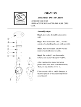
Unpacking
NOTE
Below is a list of all the items which should be in-
cluded in the shipping box(es). The first quantity
indicates the number of items which should be present
for a single lighting assembly while the second
quantity indicates the number of items which should
be present for a dual lighting assembly (Refer to
Figure 2).
1. Cut banding and remove box lid from box.
2. Remove one/two cross tube/lighthead assembly (1,
Figure 2) and inspect.
3. Remove one/two down tube assembly (2) and
inspect.
4. Remove one/two bag(s) (3) and inventory contents;
the following items should be included:
3a. Four #10-24 x 3/4" socket cap screws
3b. Two/four #10-24 x 3/8" black oxide, button head
screws
3c. Six/twelve 3/8"-16 hex nuts
3d. Three/six 3/8" lockwashers
3e. One/two #10-24 x 5/8" zinc plated
button head screws
3f. One/two #10-24 x 3/8" pan head screws
3g. One/two 100 Watt Halogen bulb
3h. One/two Sterilizable handles (inspect)
5. Remove one ceiling plate assembly (4) and inspect.
6. Remove one ceiling cover (5) and inspect.
Figure 2. Components Unpacking and Inventory
(3a) #10-24 x 3/4" Cap Screw
(3b) #10-24 x 3/8" Button Head Screw
(3c) #3/8"-16 Hex Nut)
(3d) 3/8" Lockwasher
(3g) 100 W Halogen Bulb
(3e) #10-24 x 5/8" Button Head Screw
(3f) #10-24 x 3/8" Pan Head Screw
(3h) Sterilizable Handle
Go To Table Of Contents

6
Ceiling Support Structure Installation
Weights:
• 8 ft (2.44 m) Single 355 Lighting System
(less customer supplied
ceiling structure): ...................... 59 lbs (26.8 kgs)
• 9 ft (2.74 m) Single 355 Lighting System
(less customer supplied
ceiling structure): ...................... 60 lbs (27.2 kgs)
• 8 ft (2.44 m) Dual 355 Lighting System
(less customer supplied
ceiling structure): .................... 105 lbs (47.6 kgs)
• 9 ft (2.74 m) Dual 355 Lighting System
(less customer supplied
ceiling structure): .................... 107 lbs (48.5 kgs)
Figure 3. Recommended Ceiling Mounting Locations (For Dental and Medical Applications)
Recommended Ceiling Mounting
Locations (For Dental and Medical
Applications)
See Figure 3 for recommended ceiling mounting loca-
tions. These locations allow the lighthead to be posi-
tioned over any portion of the patient's body without
running into a physical arm restriction; mounting the light
system on the centerline of the table or headrest will
result in some areas of the patient's body not being able
to be illuminated by the lighthead. Also, the light system
should be mounted on the opposite side of the table as
the doctor's work position, so the light system is not
hanging above their head.
Torques:
• 8 ft (2.44 m) Single 355
Lighting System: ................ 69 ft-lbs (94 N•m)
• 9 ft (2.74 m) Single 355
Lighting System: ................ 69 ft-lbs (94 N•m)
• 8 ft (2.44 m) Dual 355
Lighting System: ................ 136 ft-lbs (184 N•m)
• 9 ft (2.74 m) Dual 355
Lighting System: ................ 137 ft-lbs (186 N•m)
27 IN (68.6 CM)
MAX.
30 IN (76.2 CM)
27 IN (68.6 CM)
MAX.
12 IN
(30.5 CM)
MIN.
27 IN (68.6 CM)
MAX.
12 IN
(30.5 CM)
MIN.
12 IN
(30.5 CM)
MIN.
Go To Table Of Contents

7
must not be allowed to deflect more than 1/16" over a 12"
distance. The ceiling plate must be level and stay level
when the arm assemblies are rotated in every position
and all worst case scenarios (example: two sets of arm
assemblies on one side). This means that the ceiling
support structure must be braced in multiple directions.
The 355 lighting system comes in two different versions:
an 8 foot version for an 8 foot ceiling and a 9 foot version
for a 9 foot ceiling. The bottom of the ceiling plate
assembly must be installed so it is flush with the finished
surface of the facility's ceiling. See Figure 4. The ceiling
cover is designed to fit up against the finished ceiling.
Figure 4. Suggested Ceiling Support Structure Installation
(Illustration applies to Single and Dual Mounted Lighting Systems)
NOTE
The illustrations in Figure 4 are for suggestion only.
Midmark does not supply ceiling structures. Consult a
structural engineer for the best solution for your
situation.
The 355 Lighting system requires a sturdy ceiling
support structure to support the weight and the dynamic
torque which will be applied to the support structure (See
Figure 4).
The ceiling support structure must be strong enough to
uphold the weight of the system and support the rotating
suspension arms and lighthead(s) without deflection.
The 355 lighting system is engineered for ease of
movement during positioning. The arm assemblies and
lightheads(s) will rotate with a minimum of force, pro-
vided the arm assemblies are leveled and stay level. If,
however, the ceiling support is weak and flexes, the
weakness will have a negative impact on the operation of
the arm assemblies during positioning.
If the ceiling support structure flexes too much, the
lighthead(s) will drift to the lowest point. Although the
arms are equipped with brakes to prevent drift, the
undesirable side effect of stiffer braking, is that the arm
assemblies / lighthead(s) will be harder to move. For a
set of arm assemblies to rotate without drift and a
minimum amount of force, the ceiling plate assembly
Go To Table Of Contents

8
Electromagnetic Interference
This product is designed and built to minimize
electrmagnetic interference with other devices. However,
if interference is noticed between another device and this
product, remove the interfering device from the room or
wire this product into an isolated circuit.
Wiring Installation
The wiring, supplying power to the junction box of the
355 lighting system, must be supplied by the customer.
The 355 lighting system requires 220, 230 or 240 VAC
input voltage. The wire should be 2-conductor with
ground, 14 gauge copper wiring, rated for 250 VAC. The
customer supplied wiring must be connected to the
junction box with some form of strain relief fitting, prefer-
ably a conduit fitting. Connect and route the wiring
according with local and national codes, using conduit
where necessary. See wiring diagram, Figure 5, sheets
1 and 2.
Junction Box Wiring Connections
(See Figure 5, sheets 1 and 2)
WARNING
Make sure the power to the facility
supplied wiring is turned "off" for
the following step. Failure to do so could result in
electrical shock causing serious personal injury or
death.
1. Turn off facility power breaker so there
is no
power
in customer supplied wiring.
2. Loosen four screws (1, Figure 7); then pull outward
on box cover (2) and remove from junction box (3).
3. Install conduit fitting (customer supplied) in the
knockout of the junction box (3).
4. Feed the facility supplied wiring through the knock-
out in the junction box (3).
WARNING
Make sure facility supplied wiring is not
shorted to junction box and do not
touch wires during steps 5 and 6. Failure to do so
could result in electrical shock causing serious
personal injury or death.
5. Turn on facility power breaker so there
is
power in
customer supplied wiring.
6. Using a multimeter, measure the input voltage
between black power lead and white neutral lead of
customer supplied wiring. Record this voltage. See
Figure 5.
WARNING
Make sure facility supplied wiring is
turned to off for the following step.
Failure to do so could result in electrical shock
causing serious personal injury or death.
7. Turn "off" facility power breaker so there
is no
power in customer supplied wiring.
8. If voltage measured in step 6 was 225.0 VAC or
lower, connect the white neutral lead of customer
supplied wiring to the terminal marked N/220V for
single units
or
N1/220V or N2/220V for double units
(see Figure 5).
If voltage measured in step 6 was between 225.1
to 235.0 VAC, connect the white neutral lead of
customer supplied wiring to the terminal marked N/
230V for single units
or
N1/230V or N2/230V for
double units (see Figure 5).
If voltage measured in step 6 was 235.1 VAC or
higher, connect the white neutral lead of customer
supplied wiring to the terminal marked N/240V for
single units
or
N1/240V or N2/240V for double units
(see Figure 5).
9. Connect the black power wire from customer
supplied wiring to the terminal marked L.
10. Connect the green/yellow earth ground wire from
customer supplied wiring to the terminal marked
with a ground symbol.
CAUTION
Failure to properly connect and insulate
wires in junction box could result in a
short or electrical shock to personnel.
• Always use a strain relief (conduit fitting)
between facility wiring and the junction box.
• Always connect the earth ground wires inside
the junction box.
11. If light system is a dual light, the white jumper wire
on the terminal block may need to be repositioned
depending on the voltage measurement taken in
step 6. If the voltage measurement was 225 VAC
or lower, use white jumper wire to connect N1/220V
to N2/220V. If the voltage measurement was 225.1
VAC to 235.0 VAC, keep white jumper wire where it
is; connecting N1/230V to N2/230V. If the voltage
measurement was 235.1 VAC or higher, use white
jumper wire to connect N1/240V to N2/240V.
NOTE
It is especially important to perform steps 12 and 13
now if the ceiling is a drywall/plastered ceiling; these
steps cannot be performed later.
Go To Table Of Contents

9
12. Feed brown and blue transformer output wires out
of wire hole (7, Figure 7) in bottom of junction box.
13. Position box cover (2) on junction box (3) and
secure by tightening four screws (1).
Figure 5. Wiring Diagram (Sheet 1 of 2). Single units
(*) NOTE:
Select transformer input tap by measuring the input voltage. Then, connect the power lead (white wire) to
one of the following terminals according to the input voltage measured:
220 VAC - Use terminal marked N/220V.
230 VAC - Use terminal marked N/230V.
240 VAC - Use terminal marked N/240V.
JUNCTION BOX - SINGLE
TRANSFORMER
INPUT TAP LEADS
BULB
ASSEMBLY
BLACK
BLACK
BROWN
BLUE
BLUE
BLUE
BROWN
BROWN
YELLOW
RED
ORANGE
BLUE
TRANSFORMER
F1
LINE FUSE
220, 230, or 240 VAC
(SUPPLIED BY
CUSTOMER
ON / STANDBY
SWITCH
TRANSFORMER
OUTPUT LEADS
GREEN/
YELLOW
BLACK
BLACK
BLACK
WHITE
GREEN
(*)
N/240V
N/230V
N/220V
G
L
BLACK
Go To Table Of Contents

10
Figure 5. Wiring Diagram (Sheet 2 of 2). Double units
(*) NOTE:
Select transformer input tap by measuring the input voltage. Then, connect the power lead (white wire) to
one of the following terminals according to the input voltage measured:
220 VAC - Use terminal marked N/220V.
230 VAC - Use terminal marked N/230V.
240 VAC - Use terminal marked N/240V.
JUNCTION BOX - DOUBLE
T
RANSFORMERS
BLACK
BLACK
BROWN
BLUE
BROWN
BLUE
F1 LINE FUSES
220, 230, OR 240 VAC
(SUPPLIED BY CUSTOMER
T24 VAC (=/- 0.74
VAC OUTPUT
LOADED
GREEN/
YELLOW
BULB
ASSEMBLY
ON / STANDBY
SWITCH
YELLOW
RED
ORANGE
BLACK
WHITE
GREEN
(*)
N2/240V
N2/230V
N2/220V
G
L
BROWN
BLUE
BLUE
N1/240V
N1/230V
N1/220V
YELLOW
RED
ORANGE
WHITE
JUMPER WIRE
BLACK
BLACK
BROWN
BLUE
BROWN
BLUE
BLUE
BROWN
BLUE
BULB
ASSEMBLY
TRANSFORMER
INPUT TAP LEADS
ON / STANDBY
SWITCH
BLACK
BLACK
BLACK
TRANSFORMER
OUTPUT LEADS
(*)
Go To Table Of Contents

11
5
1
3
2
4
MA32850
Ceiling Plate Assembly Installation
NOTE
The following step describes one typical way of
mounting the ceiling plate assembly. However, this
method may not work for all installations; if not use the
following procedure for guidance only.
1. Install four 1/2" nuts (1, Figure 6) on four all-thread
bolts (2) (not supplied) .
2. Install ceiling plate assembly (3) on four all-thread
bolts (2) and secure with four 1/2" lockwashers (4)
and 1/2" nuts (5).
NOTE
For the following step, make sure nuts (1)
are not
contacting the ceiling plate assembly (3). Otherwise,
leveling of ceiling plate assembly with nuts (5) will not
be possible.
3. Adjust four nuts (5) until bottom of ceiling plate
assembly (3) is flush with surface of ceiling.
WARNING
Failure to install nuts (5) so that there
are at least two full threads visible
below nuts, could result in unit falling.
4. Use a level to check the levelness of ceiling plate
assembly (3) in all directions. Adjust four nuts (5)
as necessary until the ceiling plate assembly (3) is
level in all directions and flush with surface of
ceiling.
5. Tighten nuts (1) against ceiling plate assembly (3);
then recheck levelness of ceiling plate and readjust
if necessary.
Figure 6. Suggested Ceiling Plate Assembly Installation
THIS SURFACE
SHOULD BE FLUSH
WITH BOTTOM OF
CEILING
Go To Table Of Contents

12
Down Tube Installation
1. Thread three 3/8" x 16 hex nuts (4, Figure 7)
(supplied) onto three bolts (5) until they are hand-
tight; then back off each nut 1 full turn.
2. Position down tube (6) near wire hole (7).
3. Connect brown wire (A) from junction box (3) to
brown wire (A) from down tube (6).
4. Connect blue wire (B) from junction box (3) to blue
wire (B) from down tube (6).
5. Install down tube (6) on three bolts (5) and secure
with three 3/8" lockwashers (8) and 3/8" x 16 hex
nuts (9) (supplied).
WARNING
Failure to install nuts (9) so that there
are at least two full threads visible below
nuts, could result in unit falling.
6. Under normal circumstances, the down tube (6)
should be level enough to provide drift-free opera-
tion. If, after complete assembly and operation of
the light system, drifting is observed, use a protrac-
tor or level (C) to adjust nuts (9) until down tube (6)
is vertical (+/- 0.5
o
); then tighten nuts (4).
7. If light system is a dual light, repeat steps 1 through
6 for remaining down tube (6).
8. Slide ceiling cover (10) onto down tube(s) (6).
9. Attach ceiling cover (10) to ceiling plate (11) with
four #10-24 x 3/4" screws (12) (supplied).
Figure 7. Down Tube Installation
Go To Table Of Contents

13
3. Align three screw holes; then insert pivot shaft of
cross tube assembly (3) into down tube (2). Se-
cure cross tube assembly in position with two #10-
24x3/8" black oxide button head screws (5).
4. Feed two wires (4) through top window (A) of down
tube (2).
5. Connect brown wire (4) to brown wire (6) and blue
wire (4) to blue wire (6). Push wires into top
window (A).
6. Slide ball pivot sleeve (1) down into position and
secure with one #10-24x3/8" (New Units Only)
phillips head screw (7).
Cross Tube Assembly Installation
1. Slide ball pivot sleeve (1, Figure 8) onto down tube
(2), making sure screw hole in sleeve is towards
the bottom.
2. With ball pivot sleeve (1) positioned as high as
possible on down tube (2), pull blue and brown
wires (6) through top window (A) of down tube.
NOTE
There are three screw holes in cross tube (3); two of
the holes are larger and have a courser thread. Use
these two holes to secure cross tube assembly with
screws (5). The other hole is for securing ball pivot
sleeve.
Figure 8. Cross Tube Assembly Installation
Go To Table Of Contents

14
Figure 9. Bulb Installation
Bulb Installation
NOTE
Screws (1) are captive screws. Only loosen captive
screws; do not try to remove them.
1. Loosen three captive screws (1, Figure 9) and
separate top cap (2) from support arm pivot (3).
2. Remove packing material from inside of lighthead.
NOTE
Halogen bulbs are sensitive to body oils. Be sure not
to touch the glass portion of the bulb during relamping
or cleaning. Body oils create a hot spot on the bulb
and may cause the bulb to burn out prematurely. If the
glass portion of the bulb is handled, wipe with a clean,
soft, lint free cloth. Wipe with alcohol and pat dry.
WARNING (*)
The maximum allowable bulb wattage
which can be used in this light is 100
Watts. There is a risk of fire or equipment damage
if 100 Watt limit is exceeded.
MA326400
*
2
1
3
4
5
6
4
KEY
KEY HOLE
3. Using a cotton glove or similar clean cloth, grasp
the new bulb (4) (supplied) and insert new bulb into
bulb socket (5). Push bulb in until its prongs bottom
out; there should be approximately 1/16 in. (1.6
mm) gap between bulb socket and glass base of
bulb. Forcing bulb in further will cause damage.
NOTE
The top cap is keyed which allows it only to be
installed in one position.
4. Align the key of the top cap (2) with key hole in
support arm pivot (3). Then secure top cap (2) on
support arm pivot (3) by tightening three captive
screws (1). Make sure wiring (6) is tucked up
above light block as much as possible and does not
hang down into path of light.
Go To Table Of Contents

15
Housing Cap Installation
1. Install housing cap (2, Figure 12) on ballast housing
(3) and secure with screw (1).
Operational Test
1. Turn the ON / STANDBY switch (1, Fig. 10) to ON.
2. Observe. The light should illuminate.
3. Position the light 36" from the table and aim the light
at the table.
4. Observe. There should be an evenly distributed
circular pattern of bright light, approximately 8
inches in diameter, on the table surface.
1
MA547300
580
580
540
180
35
35
36"
2
3
ON
STANDBY
ON / STANDBY
CONTROL
LIGHTHEAD
LAMP TUBE
8" DIAMETER
LIGHT BEAM
(APPROXIMATE)
DOWN TUBE
CROSS TUBE
5. Rotate the lighthead, lamp tube, cross tube, and
down tube through their range of motions as shown
on the illustration (See Figure 10). Release the
lighthead at different positions.
6. Observe. The lighthead should be able to be
positioned easily through the entire range of its
motion. When the lighthead is released in any
position, no drifting should occur at any axis.
7. If any problems are discovered, refer to the trouble-
shooting guide for adjustment and repair tips.
Figure 10. Operational Test
Go To Table Of Contents

16
PROBLEM
no light from lighthead
no light from lighthead; on / standby switch
is on
no light from lighthead although the bulb
and fuse were checked; lighthead flashes
intermittently when lighthead or arms are
moved
down tube does not rotate freely or drifts
when released in desired position
lamp tube does not rotate freely or drifts
when released in desired position
cross tube rotates (at ball pivot joint) too
stiffly or drifts when released in desired
position
lighthead does not rotate freely at lamp tube
or drifts when released in desired position
POSSIBLE CAUSE
lighthead is off
bulb has burned out or
has not been installed
fuse in junction box is
blown
no power to the junction
box
transformer is malfunc-
tioning
circuit or wiring problem
within arm assemblies,
junction box, or other part
of lighting system
improper installation of
ceiling plate (deflects too
much or is not level)
brake tension needs
adjusted
ball pivot joint tension
needs to be adjusted or
cross tube counterbal-
ance needs adjusted
brake needs adjustment
SOLUTION
turn on / standby switch to on
refer to bulb installation proce-
dure in this manual
inspect/replace the fuse located
inside the ceiling cover
check for facility power to the
junction box
check for 24.5 VAC output from
transformer (when loaded).
check all wiring connections. If
problem persists, call Midmark
Technical Support: 1-800-
Midmark
check for excessive flexing of
ceiling support structure and/or
check if ceiling plate is level.
Readjust as necessary.
Call Midmark Technical Support:
1-800-Midmark
refer to ball pivot joint tension
adjustment procedure in this
manual. If proper tension cannot
be achieved, refer to the cross
tube counterbalance adjustment
procedure in this manual and
then repeat main pivot joint
tension adjustment. If problem
still persists, call Midmark
Technical Support: 1-800-
Midmark
Call Midmark Technical Support:
1-800-Midmark
Table 1. Troubleshooting Guide
TROUBLESHOOTING
Troubleshooting Guide
If any problems are discovered during the installation
process, refer to the following table (Table 1) to determine
the cause of the problem.
Go To Table Of Contents

17
ADJUSTMENTS
Ball Pivot Joint Tension Adjustment
1. Remove screw (1, Figure 11) and slide ball pivot
sleeve (2) up out of way.
2. Rotate cross tube (3) until adjustment hole (4)
appears in the adjustment window opening.
NOTE
There are three settings which the ball pivot cam (5)
can be set for: light tension, medium tension, or stiff
tension (see Figure 11). These settings may be
changed according to the operator's preference.
Figure 11. Ball Pivot Joint Tension Adjustment
3. Insert screwdriver, into adjustment hole (4). Then,
using the screwdriver, rotate ball pivot cam (5) to the
desired tension setting.
4. Remove the screwdriver and move the cross tube (3)
about the ball pivot joint in a circular motion and up
and down motion to ensure the setting is the one
desired. Move the cross tube (3) to a horizontal
position and release it. The cross tube should not
drift in any direction. If it does, a higher tension
setting is required. Repeat steps 3 and 4 until the
desired tension adjustment is achieved with no
drifting of the cross tube. If a satisfactory tension
adjustment cannot be achieved, perform the cross
tube counterbalance adjustment procedure and then
repeat the ball pivot joint tension adjustment proce-
dure.
5. Slide ball pivot sleeve (2) down into position and
secure with screw (1).
ASSEMBLY / DISASSEMBLY
POSITION
LIGHT TENSION
POSITION
MEDIUM TENSION
POSITION
STIFF TENSION
POSITION
Go To Table Of Contents

18
Cross Tube Counterbalance
Adjustment
1. Remove housing cap (1, Figure 12) from ballast
housing (2).
NOTE
One way to determine if cross tube is balanced
properly is to raise the cross tube above horizontal,
release it, and observe where it stops. Then lower the
cross tube below horizontal plane, release it, and
observe where it stops. The cross tube should return
to the horizontal position and remain there; if it does,
the cross tube counterbalance is adjusted properly.
Turning screw (3) in clockwise direction will lower the
lighthead end of cross tube. Turning screw (3) in
counterclockwise direction will raise the lighthead end
of cross tube.
2. Adjust screw (3) until cross tube balances in a
horizontal position.
Figure 12. Cross Tube Counterbalance Adjustment
3. Install housing cap (1) on ballast housing (2).
NOTE
It is recommended that you start with the light setting
and then proceed to the medium or stiff setting only if
necessary to prevent drifting.
4. Insert screwdriver, into adjustment hole (4, Figure
11). Then, using the screwdriver, rotate ball pivot
cam (5) to the light, medium, or stiff setting as
desired by the operator(s). Remove screwdriver.
5. Slide ball pivot sleeve (2) down into position and
secure with screw (1).
Go To Table Of Contents
/