Page is loading ...

Crestron MSMK-4SM
Multi-Surface Mount Kit
for TPMC-4SM(D) & TPCS-4SM(D)
Installation Guide

This document was prepared and written by the Technical Documentation department at:
Regulatory Compliance
As of the date of manufacture, the MSMK-4SM has been tested and found to comply with specifications for CE
marking and standards per EMC and Radiocommunications Compliance Labelling.
The specific patents that cover Crestron products are listed at patents.crestron.com.
Crestron and the Crestron logo are either trademarks or registered trademarks of Crestron Electronics, Inc. in the United States
and/or other countries. Other trademarks, registered trademarks and trade names may be used in this document to refer to either the
entities claiming the marks and names or their products. Crestron disclaims any proprietary interest in the marks and names of others.
©2012 Crestron Electronics, Inc.

Crestron MSMK-4SM Multi-Surface Mount Kit
Contents
Multi-Surface Mount Kit for TPMC-4SM(D) & TPCS-4SM(D): MSMK-4SM 1
Introduction ...............................................................................................................................1
Setup ..........................................................................................................................................2
Supplied Hardware......................................................................................................2
Installation................................................................................................................... 5
Resources.................................................................................................................................17
Further Inquiries ........................................................................................................17
Future Updates ..........................................................................................................17
Return and Warranty Policies ..................................................................................................18
Merchandise Returns / Repair Service ......................................................................18
Crestron Limited Warranty........................................................................................18
Installation Guide – DOC. 6848C Contents • i


Crestron MSMK-4SM Multi-Surface Mount Kit
Multi-Surface Mount Kit for
TPMC-4SM(D) & TPCS-4SM(D):
MSMK-4SM
Introduction
The Crestron
®
MSMK-4SM provides a very versatile surface mounting solution for a
TPMC-4SM or TPMC-4SMD Touch Screen. It is also compatible with TPCS-4SM
and TPCS-4SMD Touch Screen Control Systems. Using the MSMK-4SM, the touch
screen device can be mounted directly onto glass, granite, marble, plaster, smooth
stone and masonry or virtually any other flat surface using either the self-adhering
mounting plate or screws. An optional angle bracket is included to allow the touch
screen to be mounted at a fixed tilt of 20 degrees up or down.
An adhesive backed raceway is also provided for use on smooth surfaces to conceal
wires running to the touch screen from the floor or ceiling. The raceway is paintable
and is composed of three 3 foot (0.91 meter) sections plus an assortment of elbows
and couplings.
Models
DESCRIPTION MODEL NUMBER COLOR
MSMK-4SM-B-S Black Smooth Multi-Surface Mount Kit
MSMK-4SM-W-S White Smooth
For simplicity within this guide the color and texture designation are omitted and the
term “MSMK-4SM” is used, unless otherwise noted.
Installation Guide – DOC. 6848C Multi-Surface Mount Kit for TPMC-4SM(D) & TPCS-4SM(D): MSMK-4SM • 1

Multi-Surface Mount Kit Crestron MSMK-4SM
Setup
Supplied Hardware
The MSMK-4SM consists of a plastic surface mount enclosure, metal mounting
plate with adhesive backing, angled mounting bracket, plastic covers to protect
cabling openings, raceway and appropriate screws and nuts for mounting.
The multi-surface mounting option provides the necessary support and accessories
for post-construction applications. The table below lists all parts included with the
MSMK-4SM.
Supplied Hardware for the MSMK-4SM
DESCRIPTION PART NUMBER COLOR QUANTITY
4509195 White 1
Metal, Plate, Glass Mount,
Foam with Adhesive
4509522 Black 1
2024381 White 1
Plastic Enclosure, Surface
Mount
2024382 Black 1
2024621 White 1 Bracket, 20 Degree Mount
2024622 Black 1
2024491 White 2 Plastic Cover
2024492 Black 2
Raceway 2024932 White 1
Nut, #04-40, External, Hex 2004878 N/A 4
Screw, #04-40 1/4”, Steel,
Pan Head, Phillips
2007161 N/A 4
2 • Multi-Surface Mount Kit for TPMC-4SM(D) & TPCS-4SM(D): MSMK-4SM Installation Guide – DOC. 6848C

Crestron MSMK-4SM Multi-Surface Mount Kit
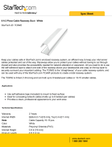
The dimensions of the MSMK-4SM are shown below and on the next page.
Glass Mounting Plate Overall Dimensions
4.50 in
(115 mm)
Angle Mounting Bracket Overall Dimensions
4.25 in
(108 mm)
2.72 in
(69 mm)
0.23 in
(6 mm)
1.12 in
(29 mm)
Installation Guide – DOC. 6848C Multi-Surface Mount Kit for TPMC-4SM(D) & TPCS-4SM(D): MSMK-4SM • 3

Multi-Surface Mount Kit Crestron MSMK-4SM
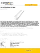
Plastic Enclosure Overall Dimensions (Rear View)
3.75 in
(96 mm)
3.00 in
(77 mm)
3.25 in
(83 mm)
2.10 in
(54 mm)
2.00 in
(51 mm)
Plastic Enclosure Overall Dimensions (Bottom View)
6.16 in
(157 mm)
0.88 in
(23 mm)
0.55 in
(14 mm)
4 • Multi-Surface Mount Kit for TPMC-4SM(D) & TPCS-4SM(D): MSMK-4SM Installation Guide – DOC. 6848C

Crestron MSMK-4SM Multi-Surface Mount Kit
Installation
This section provides an installation procedure for each mounting scenario. “Glass
Mounting” starts below, “Drywall, Paneling, Concrete or Brick Mounting” starts on
page 11 and “Raceway Mounting” is on page 16. Be sure to review each procedure
before starting.
Glass Mounting
The touch screen can be mounted onto a flat pane of glass or similar smooth surface
(such as granite, marble, plaster, smooth stone or masonry) using the included glass
mounting plate. The back of the plate has an adhesive tape that permanently attaches
to the glass. The touch screen can be flat mounted or angle mounted to the glass
mounting plate by following the appropriate procedure below. After installation is
complete, the raceway kit may be installed on a smooth surface by following the
“Raceway Mounting” procedure on page 16.
NOTE: Ensure the glass mounting surface is cleaned with a glass cleaning product
that does not leave a film and is free of debris before mounting. Once glass mounting
plate has been attached, it cannot be easily removed.
Flat Mounting
Complete the following procedure to attach the glass mounting plate. The only tools
and supplies required and not supplied are a level, tape, #2 Phillips screwdriver, 1/4”
hex driver and a glass cleaning product that does not leave a film. A T8 Torx bit is
supplied with the touch screen.
1. Thoroughly clean and dry the glass mounting surface using a glass cleaning
product that does not leave a film.
2. Using the level, carefully tape a horizontal reference line that coincides with
the lower edge of the mounting bracket.
CAUTION: Adhesive on glass mounting plate is a high strength bond.
Once adhesive meets a surface, it cannot be easily removed or adjusted.
3. Remove the adhesive backing from the glass mounting plate.
4. Holding the glass mounting plate (4509195 or 4509522) at a 45 degree
angle to the glass, carefully align the lower edge of the mounting plate with
the level taped line. Do not allow adhesive backing to come in contact with
the glass.
5. Once aligned with the level reference line, carefully tilt the glass mounting
plate back until it is secured to the glass. Firmly press glass mounting plate
to the glass to ensure proper adhesion and that any trapped air bubbles are
removed.
6. Using a flathead screwdriver, carefully separate the back cover of the touch
screen from the front of the unit. This part is not used. Refer to the
following illustration.
Installation Guide – DOC. 6848C Multi-Surface Mount Kit for TPMC-4SM(D) & TPCS-4SM(D): MSMK-4SM • 5

Multi-Surface Mount Kit Crestron MSMK-4SM
Separate Back Cover of Touch Screen
Insert screwdriver to separate back of touch screen
NOTE: If installed, the two security screws must be removed
before separating the back cover of the touch screen.
7. Insert the plastic cover (2024491 or 2024492) into top or bottom of the
plastic enclosure (2024381 or 2024382). Installation location of the plastic
cover is determined through the location of the raceway. For example, if the
raceway is to be run to the top of the plastic enclosure, install the plastic
cover in the bottom of the plastic enclosure.
8. Run the network wiring through the hole in the back of the plastic
enclosure.
9. Attach the plastic enclosure to the glass mounting plate using the 1/4” hex
driver and the four included #04-40 hex nuts (2004878). Observe the
orientation of the TOP screening to ensure proper installation of the plastic
enclosure. Refer to the illustration below.
Plastic Enclosure Mounting Using Glass Mounting Plate
Glass
Plastic Enclosure
(2024381 or 2024382)
Nut (4) #04-40 Hex
(2004878)
Glass Mounting Plate
(4509195 or 4509522)
Plastic Cover
(2024491 or 2024492)
6 • Multi-Surface Mount Kit for TPMC-4SM(D) & TPCS-4SM(D): MSMK-4SM Installation Guide – DOC. 6848C

Crestron MSMK-4SM Multi-Surface Mount Kit
NOTE: When raceway is run to the bottom of the touch screen, the plastic
cover must be placed in the top of the plastic enclosure. When raceway is
run to the top of the touch screen, the plastic cover must be placed in the
bottom of the plastic enclosure.
10. Attach the RJ-45 connector of the network wiring to the touch screen and
then install the touch screen by carefully pressing it into place. While
snapping the unit into place, pull the network wiring to remove slack. Refer
to the illustration below.
NOTE: Use care when pulling plenum rated cable through the bottom of
the plastic enclosure, the rigidity of the cable causes slight resistance.
Touch Screen Mounting Using Glass Mounting Plate (Exploded View)
Glass
Plastic Enclosure
(2024381 or 2024382)
Nut (4) #04-40 Hex
(2004878)
Touch Screen
(Sold Separately)
Glass Mounting Plate
(4509195 or 4509522)
Plastic Cover
(2024491 or 2024492)
11. Secure the touch screen to the plastic enclosure with Phillips head screws.
Alternatively, security Torx screws can be installed using a Torx
screwdriver bit (both included with touch screen), as shown in the following
illustration.
Installation Guide – DOC. 6848C Multi-Surface Mount Kit for TPMC-4SM(D) & TPCS-4SM(D): MSMK-4SM • 7

Multi-Surface Mount Kit Crestron MSMK-4SM
Secure Touch Screen with Screws (Mounting Surface Not Shown)
Angle Mounting
To install the angle mounting bracket, complete steps 1-7 of the “Flat Mounting”
procedure which starts on page 5. Continue with this procedure to assemble the
angle mounting bracket with the glass mounting plate.
1. Using a 1/4” hex driver, install the angle mounting bracket (2024621 or
2024622) onto the glass mounting plate with the four included hex nuts
(2004878). Refer to the illustration on the following page.
NOTE: Angle mounting bracket may be oriented to tilt the touch screen 20
degrees up or down, depending on the application.
8 • Multi-Surface Mount Kit for TPMC-4SM(D) & TPCS-4SM(D): MSMK-4SM Installation Guide – DOC. 6848C

Crestron MSMK-4SM Multi-Surface Mount Kit
Attach Angle Mounting Bracket
Glass
Angle Mounting Bracket
(2024621 or 2024622)
Nut (4) #04-40 Hex
(2004878)
Glass Mounting Plate
(4509195 or 4509522)
2. Run the network wiring through the hole in the back of the plastic
enclosure.
3. Attach the plastic enclosure (2024381 or 2024382) to the angle mounting
bracket with the four included #04-40 x 1/4” Phillips head screws
(2007161), as shown in the illustration on the following page. Observe the
orientation of the TOP screening to ensure proper installation of the plastic
enclosure.
Installation Guide – DOC. 6848C Multi-Surface Mount Kit for TPMC-4SM(D) & TPCS-4SM(D): MSMK-4SM • 9

Multi-Surface Mount Kit Crestron MSMK-4SM
Attach Plastic Enclosure to Angle Mounting Bracket
Glass
Screw (4) #04-40 x 1/4"
Pan Head, Phillips
(2007161)
Glass Mounting Plate
(4509195 or 4509522)
Angle Mounting Bracket
(2024621 or 2024622)
Plastic Enclosure
(2024381 or 2024382)
NOTE: When raceway is run to the bottom of the touch screen, the plastic
cover must be placed in the top of the plastic enclosure. When raceway is
run to the top of the touch screen, the plastic cover must be placed in the
bottom of the plastic enclosure.
4. Attach the RJ-45 connector of the network wiring to the touch screen and
then install the touch screen by carefully pressing it into place. While
snapping the unit into place, pull the network wiring to remove slack. Refer
to the illustration on the following page.
10 • Multi-Surface Mount Kit for TPMC-4SM(D) & TPCS-4SM(D): MSMK-4SM Installation Guide – DOC. 6848C

Crestron MSMK-4SM Multi-Surface Mount Kit
Touch Screen Mounting Using MSMK-4SM and Angle Mounting Bracket (Exploded View)
Glass
Screw (4) #04-40 x 1/4"
Pan Head, Phillips
(2007161)
Glass Mounting Bracket
(4509195 or 4509522)
Angle Mounting Bracket
(2024621 or 2024522)
Touch Screen
(Sold Separately)
Plastic Enclosure
(2024381 or 2024382)
5. Secure the touch screen to the plastic enclosure with Phillip head screws.
Alternatively, security Torx screws can be installed using a Torx
screwdriver bit (both included with touch screen), as shown in the
illustration on page 8.
Drywall, Paneling, Concrete or Brick Mounting
This section provides the steps required for assembly and installation of the
MSMK-4SM onto drywall, paneling, concrete or brick. The touch screen can be flat
mounted or angle mounted onto the surface by following the appropriate procedure
below. After installation is complete, the raceway may be installed following the
“Raceway Mounting” procedure on page 16.
Flat Mounting
Review the procedure and complete the steps in the order provided. The only tools
or materials required and not supplied are appropriate drywall or concrete screws,
#2 Phillips screwdriver, T8 Torx bit, 1/4” hex driver and a level. A T8 Torx bit is
supplied with the touch screen.
1. Insert the plastic cover (2024491 or 2024492) into the top or bottom of the
plastic enclosure (2024381 or 2024382). Installation location of the plastic
cover is determined by the location of the raceway. For example, if the
raceway is to be run to the top of the plastic enclosure, install the plastic
cover in the bottom of the plastic enclosure.
2. Run the network wiring through the hole in the back of the plastic
enclosure.
Installation Guide – DOC. 6848C Multi-Surface Mount Kit for TPMC-4SM(D) & TPCS-4SM(D): MSMK-4SM • 11

Multi-Surface Mount Kit Crestron MSMK-4SM
3. Using the level and appropriate screws, mount the plastic enclosure
(2024381 or 2024382). Observe the orientation of the TOP screening to
ensure proper installation of the plastic enclosure.
4. Using a flathead screwdriver, carefully separate the back cover of the touch
screen from the front of the unit. This part is not used.
5. Attach the RJ-45 connector of the network wiring to the touch screen and
then install the touch screen by carefully pressing it into place. While
snapping the unit into place, pull the network wiring to remove slack. Refer
to the illustration below.
NOTE: Use care when pulling plenum rated cable through the bottom of
the plastic enclosure, the rigidity of the cable causes slight resistance.
Mount Touch Screen to Drywall with Raceway
Drywall
Drywall
Screws (2)
(Not Supplied)
Touch Screen
(Sold Separately)
Raceway
(2024932)
Plastic Enclosure
(2024381 or 2024382)
NOTE: Raceway can be run to the top or bottom of the touch screen.
When raceway is run to the bottom of the touch screen, the plastic cover
must be placed in the top of the plastic enclosure. When raceway is run to
the top of the touch screen, the plastic cover must be placed in the bottom of
the plastic enclosure.
NOTE: The raceway is intended for installation on smooth surfaces such
as glass, drywall or paneling.
12 • Multi-Surface Mount Kit for TPMC-4SM(D) & TPCS-4SM(D): MSMK-4SM Installation Guide – DOC. 6848C

Crestron MSMK-4SM Multi-Surface Mount Kit
6. Secure the touch screen to the plastic enclosure with Phillip head screws.
Alternatively, security Torx screws can be installed using a Torx
screwdriver bit (both included with touch screen), as shown in illustration
on page 8.
Angle Mounting
1. Using the level and appropriate screws, mount the angle mounting bracket
(2024621 or 2024622), as shown in the illustration below.
Mount Angle Mounting Bracket to Mounting Surface
Mounting
Surface
Angle Mounting Bracket
(2024621 or 2024622)
Drywall or
Concrete
Screws (2)
2. Insert the plastic cover (2024491 or 2024492) into the top or bottom of the
plastic enclosure (2024381 or 2024382). Installation location of the plastic
cover is determined by the location of the raceway. For example, if the
raceway is to be run to the top of the plastic enclosure, install the plastic
cover in the bottom of the plastic enclosure.
3. Run the network wiring through the hole in the back of the plastic
enclosure.
Installation Guide – DOC. 6848C Multi-Surface Mount Kit for TPMC-4SM(D) & TPCS-4SM(D): MSMK-4SM • 13

Multi-Surface Mount Kit Crestron MSMK-4SM
4. Attach the plastic enclosure to the angle mounting bracket with the four
included #04-40 x 1/4” Phillips head screws (2007161). Observe the
orientation of the TOP screening to ensure proper installation of the plastic
enclosure. Refer to the following illustration.
Attach Plastic Enclosure to Angle Mounting Bracket
Glass
Screw (4) #04-40 x 1/4"
Pan Head, Phillips
(2007161)
Glass Mounting Plate
(4509195 or 4509522)
Angle Mounting Bracket
(2024621 or 2024622)
Plastic Enclosure
(2024381 or 2024382)
5. Using a flathead screwdriver, carefully separate the back plastic of the touch
screen from the front of the unit. This part is not used.
6. Attach the RJ-45 connector of the network wiring to the touch screen and
then install the touch screen by carefully pressing it into place. While
snapping the unit into place, pull the network wiring to remove slack. Refer
to the illustration on the following page.
14 • Multi-Surface Mount Kit for TPMC-4SM(D) & TPCS-4SM(D): MSMK-4SM Installation Guide – DOC. 6848C

Crestron MSMK-4SM Multi-Surface Mount Kit
Touch Screen Mounting Using MSMK-4SM and Angle Mounting Bracket (Exploded View)
Mounting
Surface
Angle Mounting Bracket
(2024621 or 2024622)
Screw (4) #04-40 x 1/4"
Pan Head, Phillips
(2007161)
Touch Screen
(Sold Separately)
Plastic Enclosure
(2024381 or 2024382)
Plastic Cover
(2024491 or 2024492)
7. Secure the touch screen to the plastic enclosure with Phillip head screws.
Alternatively, security Torx screws can be installed using a Torx
screwdriver bit (both included with touch screen), as shown in illustration
on page 8.
Installation Guide – DOC. 6848C Multi-Surface Mount Kit for TPMC-4SM(D) & TPCS-4SM(D): MSMK-4SM • 15

Multi-Surface Mount Kit Crestron MSMK-4SM
Raceway Mounting
This section provides the steps required for assembly and installation of the raceway
to conceal and organize cabling to the touch screen. The kit contains three cable
channels, two flat elbows, one inside elbow, one outside elbow and two couplings.
The raceway may be run to either the top or the bottom of the touch screen. Review
the procedure and complete the steps in the order provided. After installation, the
raceway can be painted.
NOTE: Surface must be clean before installation.
NOTE: Do not use on textured surfaces.
NOTE: The raceway is intended for installation on smooth surfaces, such as glass,
drywall or paneling.
1. Cut raceway to desired length.
2. Insert cables into raceway and press to snap shut.
3. Peel liner from the back of the raceway to expose adhesive strip.
4. Press firmly against wall. Use elbows and couplings as necessary.
16 • Multi-Surface Mount Kit for TPMC-4SM(D) & TPCS-4SM(D): MSMK-4SM Installation Guide – DOC. 6848C
/