Page is loading ...

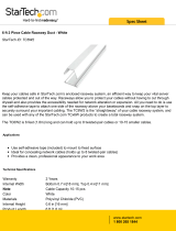
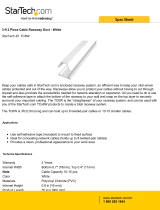
The Crestron® TS-7-MSMK and TS-10-MSMK multisurface mount kits provide a versatile flush
mount solution for Crestron TSS-7, TSS-10, TSW-760, and TSW-1060 touch screens. Using the
TS-7-MSMK or TS-10-MSMK, the touch screen may be mounted directly onto glass, granite,
marble, plaster, smooth stone and masonry, or almost any other flat surface.
The TS-7-MSMK and TS-10-MSMK rear housing provides four cutout holes (on the top, bottom,
and sides of the housing) for running concealed cables to the touch screen using the included
adhesive-backed raceway. A plastic cover with an opening for the raceway is attached to the
rear housing to conceal any unused cutouts.
NOTE: For simplicity within this guide, the term “MSMK” is used to refer to both the TS-7-MSMK
and TS-10-MSMK except where noted.
Check the Box
Item Qty
TS-7-MSMK or TS-10-MSMK
Coupler, Plastic (P/N 2049574) 2
Fitting, Plastic, Inside Corner (P/N 2049571) 1
Fitting, Plastic, Outside Corner (P/N 2049572) 1
Fitting, Plastic, Right Angle (P/N 2049573) 2
Raceway, PVC, 3 ft x 0.45 in. x 0.77 in. (P/N 2049567) 3
Screw, 4-40 x 3/8 in., Undercut Head, Phillips, Black (P/N 2007173) 4
TS-7-MSMK-B and TS-7-MSMK-W Only
Template, Overlay, Mounting Cap, TS-7-MSMK (P/N 4530137) 1
Template, Overlay, Mounting Housing, TS-7-MSMK (P/N 4530129) 1
TS-10-MSMK-B and TS-10-MSMK-W Only
Template, Overlay, Mounting Cap, TS-10-MSMK (P/N 4529858) 1
Template, Overlay, Mounting Housing, TS-10-MSMK (P/N 4530128) 1
TS-7-MSMK-B Only
Bracket, Plastic, with Adhesive, Black (P/N 4529616) 1
Cap, Plastic, with Adhesive, Black (P/N 4529618) 1
Cover, Plastic, with Detents, Black (P/N 2052978) 1
TS-7-MSMK-W Only
Bracket, Plastic, with Adhesive, White (P/N 4529615) 1
Cap, Plastic, with Adhesive, White (P/N 4529617) 1
Cover, Plastic, with Detents, White (P/N 2052977) 1
TS-10-MSMK-B Only
Bracket, Plastic, with Adhesive, Black (P/N 4529597) 1
Cap, Plastic, with Adhesive, Black (P/N 4529599) 1
Cover, Plastic, with Detents, Black (P/N 2052933) 1
TS-10-MSMK-W Only
Bracket, Plastic, with Adhesive, White (P/N 4529596) 1
Cap, Plastic, with Adhesive, White (P/N 4529598) 1
Cover, Plastic, with Detents, White (P/N 2052932) 1
Install the MSMK
The following is required for this installation: a level, a roll of masking tape, a Phillips
screwdriver, and a surface cleaning product that does not leave a film.
Use the following procedures to mount the MSMK onto a flat pane of glass or a similar smooth
surface (such as granite, marble, plaster, or smooth stone and masonry). The adhesive on the
MSMK mounting bracket attaches permanently to the surface.
Position the Rear Housing Template
An overlay template for the rear housing is provided with the MSMK to help ensure that it
remains level during installation.
NOTE: The rear housing template included with the TS-7-MSMK has the same dimensions as a
TSS-7 or TSW-760, and the rear housing template included with the TS-10-MSMK has the same
dimensions as a TSS-10 or TSW-1060. The template can be used as a reference to help select
and mark a mounting location for the MSMK.
To attach the rear housing template:
1. Clean and dry the mounting surface thoroughly.
2. Select a mounting location for the MSMK and the raceway kit, and determine whether the
raceway will be entering the MSMK from the top, bottom, left, or right cutout.
3. Use a level and masking tape to attach the included rear housing template to the surface
at the chosen location. Ensure that the template is level before proceeding.
Rear housing
template
Level
Mounting
surface
Install the Raceway Kit
The included raceway kit is designed to be installed on a nearby smooth surface to conceal
cables running to the touch screen from the floor, ceiling, or an adjacent wall, pillar, or mullion.
The raceway kit contains three cable channels, two flat elbows, one inside elbow, one outside
elbow, and two couplings.
The raceway may be painted after installation to match the walls or the surrounding decor.
CAUTION: The raceway kit must be installed prior to installing the MSMK, and the location of
the raceway cannot be changed once the MSMK is installed. The raceway kit cannot be installed
on textured surfaces.
To install the raceway kit:
1. Create a raceway cutout by removing the appropriate perforated strip from the rear
housing template. For example, if the raceway will enter the MSMK from the left side,
remove the left perforated strip from the template.
2. Use a level and the reference line on the template that is perpendicular to the chosen
raceway cutout to tape a reference guide over the center cutout.
Use reference line
perpendicular to
raceway cutout to tape
a reference guide
Remove appropriate
perforated strip from
template to create
a raceway cutout
Reference line (4)
Raceway cutout
strip (4)
Level
3. Use the template guides to cut the raceway to the required length. The end of the raceway
that will enter the MSMK can also be cut to a specific shape for a finished appearance.
4. Route all necessary cables into the raceway. Press the sides of the raceway together to
snap it shut.
5. Remove the protective liner from the rear of the raceway.
6. Use the chosen raceway cutout in the template and the taped reference line to position
the raceway on the mounting surface. Ensure the raceway is level prior to adhesion.
CAUTION: The end of the raceway must not extend beyond the taped reference line. The
rear housing will not install properly if the raceway extends beyond this line.
NOTE: The included plastic cover can be used as a template to help ensure that the
raceway is level prior to adhesion.
Raceway
Raceway
cutout
Level
7. Press the raceway firmly against the mounting surface until it adheres completely.
8. Attach any elbows, couplings, and additional cable channels as necessary.
9. Remove the taped reference guide from the surface and template.
TS-7-MSMK/TS-10-MSMK
Multisurface Mount Kits for TSS-7, TSS-10, TSW-760, and TSW-1060, Flat

Attach the Rear Housing to the Surface
1. Place the included plastic cover into the center cutout of the rear housing template so that
the end of the raceway enters the opening in the plastic cover. Ensure that the opening in
the cover is facing toward the mounting surface.
Plastic cover
Align opening in
plastic cover with
end of raceway
2. While holding the cover in place, tape the outer ring of the cover to the template.
CAUTION: The tape must not be attached to the inner ring or the flat front surface of
the plastic cover, as it cannot be removed easily once the rear housing is installed. The
illustration below shows the correct application of the tape.
3. Loosely route the cables from the MSMK through the raceway opening in the plastic cover
and out of the appropriate cutout (top, bottom, left, or right) of the rear housing.
4. Remove the protective liner from the back of the rear housing.
CAUTION: The adhesive on the back of the rear housing is high-strength bond. Once the
adhesive comes in contact with a surface, it cannot be removed easily.
5. Hold the rear housing at an angle so that the short, straight edge of the housing with the
chosen raceway cutout mates with the end of the raceway. Do not allow the adhesive to
come in contact with the surface.
6. Slide the circular base of the rear housing into the plastic cover without allowing the
adhesive to come in contact with the surface. Two detents in the plastic cover help to lock
the housing into the cover while providing some “play” for leveling.
7. Place a level on top of the rear housing.
8. After confirming that the rear housing is level, press its circular base to the mounting
surface firmly to ensure proper adhesion and to eliminate any trapped air bubbles.
NOTE: The adhesive wet area (the total area of the adhesive that is free of air bubbles or
debris) must be 60% or greater.
Rear housing
Tape the outer
ring of the
plastic cover
to the template
Plastic cover
Level
Attach the TSW-760/1060 Mounting Bracket to the MSMK
1. Cut the rear housing template off of the surface and remove any existing tape guides.
2. Use the included 4-40 x 3/8 in. screws to attach the TSW-760/1060 mounting bracket
(included with the touch screen) to the four screw holes in the rear housing.
• Ensure that the “TOP” text on the TSW-760/1060 mounting bracket is right side up.
• Use a level to adjust the mounting bracket position to ensure it is centered and level.
TSW-760/1060
mounting bracket
Rear housing
Screws (4):
4-40 x 3/8 in.
Raceway
Level
Attach the Touch Screen to the MSMK
1. Connect all cables to the rear of the touch screen.
2. Push the touch screen gently into the mounting bracket until the rear of the touch screen
snaps into place inside the mounting bracket.
TSW-760/1060
mounting bracket
Touch
screen
Install the Plastic Cap (Optional)
To provide a finished appearance for installations on glass or other transparent surfaces, install
the included molded plastic cap on the opposite side of the surface behind the MSMK:
To install the plastic cap:
1. Clean and dry the rear of the mounting surface thoroughly.
2. Use a level to align the included plastic cap template with the circular base of the mounting
bracket on the opposite side of the surface.
3. Tape the plastic cap template to the mounting surface.
4. Remove the protective liner from the rear of the plastic cap.
CAUTION: The adhesive on the rear of the plastic cap is high-strength bond. Once the
adhesive comes in contact with a surface, it cannot be removed easily. If the logo on the
plastic cap is crooked after installation, it cannot be rotated.
5. Using the overlay template as a guide, hold the plastic cap over the center of the rear
housing’s circular base, and then align the four dots on the plastic cap with the four lines on
the template. Do not allow the adhesive to come in contact with the surface.
6. Attach the plastic cap to the surface, starting with the bottom edge. Press the plastic
cover to the surface firmly to ensure proper adhesion and to eliminate any trapped air
bubbles.
MSMK mounting
bracket (rear)
Plastic
cap
Align the four
dots on the plastic
cap with the
four lines on the
overlay template
Mounting
surface (rear)
Additional Information
Scan or click the QR code for detailed product information.
TS-7-MSMK TS-10-MSMK
Compliance and Legal
Original Instructions: The U.S. English version of this document is the original instructions. All other languages are a translation
of the original instructions.
The product warranty can be found at www.crestron.com/warranty.
The specific patents that cover Crestron products are listed at www.crestron.com/legal/patents.
Certain Crestron products contain open source software. For specific information, please visit www.crestron.com/opensource.
Crestron and the Crestron logo are either trademarks or registered trademarks of Crestron Electronics, Inc. in the United
States and/or other countries. Other trademarks, registered trademarks, and trade names may be used in this document to
refer to either the entities claiming the marks and names or their products. Crestron disclaims any proprietary interest in the
marks and names of others. Crestron is not responsible for errors in typography or photography.
©2019 Crestron Electronics, Inc.
Crestron Electronics, Inc.
15 Volvo Drive, Rockleigh, NJ 07647
Tel: 888.CRESTRON
Fax: 201.767.7576
www.crestron.com
Quick Start - Doc. 8428A
(2053192)
03.19
Specifications subject to
change without notice.
/