Page is loading ...

44208-00006-000 DSV3-SP User’s Manual Rev 0B
2/12/2009
Title: DSV3-SP User’s Manual
Document Number: 4208-00006-000
Revision: 0B
Author: __________________________________________________ Date:___________
John Hufnagel, Director of Operations
Reviewer: __________________________________________________ Date:___________
Joe Ruggiero, Lead Software Engineer
Reviewer: __________________________________________________ Date:___________
Scott Robinson, Hardware Manager
Reviewer: __________________________________________________ Date:___________
Steve Blackmore, CEO
Reviewer: __________________________________________________ Date:___________
Joe Delaney, VP of Sales & Marketing
Reviewer: __________________________________________________ Date:___________
Brian Feick, CFO
Approver: __________________________________________________ Date:___________
Dan Tuck, VP of Engineering & Operations

44208-00006-000 DSV3-SP User’s Manual Rev 0B
2/12/2009
1
Copyright © 2009 by Datastrip, Inc. All rights reserved.
Reproduction in whole or in part is prohibited.
DSV3-SP User’s Manual

44208-00006-000 DSV3-SP User’s Manual Rev 0B
2/12/2009
2
Copyright © 2009 by Datastrip, Inc. All rights reserved.
Reproduction in whole or in part is prohibited.
Disclaimer Notice:
Datastrip Inc., Datastrip Ltd., Datastrip Products Inc., and related operating companies (hereafter
collectively referred to as Datastrip) reserve the right to change options, features, specifications, policies,
pricing, and availability at any time. Datastrip is not liable for errors or omissions in any product related
documentation, specifications, or software. Datastrip makes no claims of suitability for any particular
application. Datastrip will not be held liable for direct or indirect damages, or other losses due to loss of
data, reliability, or performance issues relating to Datastrip-provided equipment or software.
Copyright Notice:
No part of this publication may be reproduced, stored in a retrieval system, or transmitted in any form or
by any means, electronic, mechanical, photocopying, recording, scanning, or otherwise, except as
permitted under section 107 or 108 of the 1976 United States Copyright Act, without the prior written
permission from Datastrip. Requests to Datastrip for permission should be addressed to:
Datastrip Inc.
1285 Drummers Lane Suite 105
Wayne, PA 19087-1572 USA or
Datastrip Ltd.
1, Thame Park Business Centre
Wenman Road
Thame, Oxfordshire, OX9 3XA UK
Acknowledgements
• DSV3 is a registered trademark of Datastrip.
• Windows and WinCE are registered trademarks of Microsoft Corporation.
• All other trademarked or copyrighted names mentioned herein are the property of their respective owners.
Revision History
DATE AUTHOR REV DESCRIPTION OF CHANGE
10/30/2008 John Hufnagel 0A Initial draft release
02/12/2009 Dan Tuck 0B Updated draft
•

44208-00006-000 DSV3-SP User’s Manual Rev 0B
2/12/2009
3
Copyright © 2009 by Datastrip, Inc. All rights reserved.
Reproduction in whole or in part is prohibited.
Table of Contents
1
OVERVIEW ..........................................................................................................................................5
2
UNPACKING & INVENTORY...........................................................................................................6
3
INITIAL SETUP ...................................................................................................................................6
4
SYSTEM OVERVIEW.........................................................................................................................7
4.1
P
OWERING
U
P THE
S
YSTEM AND
S
YSTEM
S
TARTUP
S
EQUENCE
......................................................................7
4.2
P
OWER
S
TATUS
LED
I
NDICATORS
....................................................................................................................8
4.3
P
OWER
S
TATUS
T
ONE
I
NDICATORS
...................................................................................................................9
4.4
B
ATTERY
C
HARGING AND
R
EPLACEMENT
........................................................................................................9
4.4.1
Battery Capacity and Charging ................................................................................................................10
4.5
K
EYPAD AND
F
UNCTION
B
UTTONS
..................................................................................................................10
4.6
S
OFTWARE
I
NPUT
P
ANEL
/
K
EYBOARD
...........................................................................................................11
4.7
LCD
D
ISPLAY
&
T
OUCH
S
CREEN
....................................................................................................................11
4.8
F
INGERPRINT
S
ENSOR
......................................................................................................................................11
4.8.1
Fingerprint Sensor –NIST FIPS 201/SP 800-76 Compliant.....................................................................11
4.8.2
Fingerprint Sensor Calibration .................................................................................................................11
4.8.3
Finger Placement Guidelines ...................................................................................................................11
4.9
C
LEANING THE
LCD
T
OUCH
S
CREEN AND
F
INGERPRINT
S
ENSOR
................................................................12
4.10
I/O
P
ORT
A
CCESS
.............................................................................................................................................12
4.10.1
USB Ports.................................................................................................................................................12
4.10.2
Compact Flash (CFIO) Slot......................................................................................................................12
4.10.3
Secure Digital Memory Card (SDIO) Slot ...............................................................................................12
4.10.4
Audio Headset Jack..................................................................................................................................13
4.11
C
ONTACTLESS
S
MART
C
ARD
R
EADER
............................................................................................................13
4.12
D
IGITAL
S
TILL
C
AMERA
P
ERIPHERAL
M
ODULE
............................................................................................13
4.12.1
Digital Still Camera Installation Instructions ...........................................................................................13
4.13
P
OINT
&
S
HOOT
S
CANNER
P
ERIPHERAL
M
ODULE
.........................................................................................14
4.13.1
Point & Shoot Scanner Installation Instructions ......................................................................................14
5
BASIC OPERATION..........................................................................................................................15
5.1
S
TYLUS
U
SAGE
..................................................................................................................................................15
5.2
T
OUCH
S
CREEN
A
DJUSTMENTS
.......................................................................................................................15
5.3
P
OWER
M
ANAGEMENT
.....................................................................................................................................15
5.3.1
Power Management States .......................................................................................................................15
5.4
B
ATTERY
G
AUGE
..............................................................................................................................................17
5.4.1
Charging States ........................................................................................................................................17
5.4.2
Battery Charge Level States.....................................................................................................................17
5.4.3
Other Indicators........................................................................................................................................17
5.5
C
REATING
D
ESKTOP
S
HORTCUTS
....................................................................................................................18
5.6
S
AFE
B
OOT
M
ODE
............................................................................................................................................18
6
SOFTWARE UTILITIES...................................................................................................................18
6.1
S
OFTWARE
V
ERSION
U
TILITY
(D
ATASTRIP
DSV
ERIFY
2A
BOUT
.
EXE
)............................................................18
6.2
D
S
V
ERIFY
R
EGISTRY
I
NSTALL
U
TILITY
(D
S
V
ERIFY
R
EG
I
NST
.
EXE
)..............................................................18
6.3
D
S
V
ERIFY
R
EGISTRY
S
AVER
U
TILITY
(R
EGISTRY
S
AVER
.
EXE
).....................................................................19
6.4
F
INGERPRINT
C
APTURE
U
TILITY
(D
S
V
ERIFY
F
P
C
APTURE
T
EST
.
EXE
).............................................................19
7
LOADING SOFTWARE AND FIRMWARE..................................................................................19
7.1
L
OADING
DSV3
S
OFTWARE
U
PDATES
.............................................................................................................19
7.1.1
DSV3 Software Update Procedure: Using a CF Card.............................................................................19
7.1.2
DSV3 Software Update Procedure: Using a USB Flash Drive ...............................................................20
7.1.3
DSV3 Software Update Procedure: Using an FTP site ...........................................................................20
7.2
L
OADING
S
MARTCARD
F
IRMWARE
U
PDATES
.................................................................................................20

44208-00006-000 DSV3-SP User’s Manual Rev 0B
2/12/2009
4
Copyright © 2009 by Datastrip, Inc. All rights reserved.
Reproduction in whole or in part is prohibited.
7.3
L
OADING
D
IGITAL
S
TILL
C
AMERA
F
IRMWARE
U
PDATES
..............................................................................21
7.4
L
OADING
E
MBEDDED
C
ONTROLLER
(EC)
F
IRMWARE
U
PDATES
...................................................................21
8
DSV3-SP PRODUCT SPECIFICATIONS .......................................................................................22
9
REGULATORY COMPLIANCE STATEMENT ...........................................................................23
10
SOFTWARE DEMO APPLICATIONS........................................................................................24
10.1
D
IGITAL
S
TILL
C
AMERA
D
EMO
A
PPLICATION
(D
S
V
ERIFY
S
TILL
C
AMERA
T
EST
.
EXE
)..................................24
10.2
S
MART
C
ARD
R
EADER
&
S
CANNER
D
EMO
(S
UPER
V
IEWER
.
EXE
)..................................................................25
10.3
PIV
C
ARD AND
CHUID
V
ERIFIER
(D
ATASTRIP
PIVC
ARD
_CHUIDV
ERIFIER
.
EXE
).....................................27
10.4
D
ATA
C
APTURE
E
NROLLMENT
A
PPLICATION
(D
ATA
C
APTURE
.
EXE
)............................................................29
11
ACTIVE SYNC ................................................................................................................................29
11.1
A
CTIVE
S
YNC VIA
USB
2.0
C
LIENT
P
ORT
........................................................................................................30
11.1.1
Hardware/Software Requirements ...........................................................................................................30
11.1.2
PC Configuration for USB 2.0 ActiveSync (First Time Only) ................................................................30
11.1.3
Establishing a Connection........................................................................................................................30
11.1.4
Troubleshooting the Connection ..............................................................................................................30
11.2
A
CTIVE
S
YNC VIA THE
D
OCKING
S
TATION
......................................................................................................30
11.2.1
Software/Hardware Requirements and Setup...........................................................................................30
11.2.2
Establishing the Connection.....................................................................................................................30
11.2.3
Disconnect................................................................................................................................................31
11.2.4
Troubleshooting the Connection ..............................................................................................................31
12
DOCKING STATION.....................................................................................................................31
12.1
D
OCKING
S
TATION
I/O ....................................................................................................................................32
12.2
A
DJUSTING THE
D
OCKING
S
TATION
B
ACKREST
.............................................................................................32
13
TROUBLESHOOTING ..................................................................................................................32
14
AVAILABLE PARTS, SUPPLIES, AND ACCESSORIES.........................................................34
15
SERVICE & SUPPORT..................................................................................................................35

44208-00006-000 DSV3-SP User’s Manual Rev 0B
2/12/2009
5
Copyright © 2009 by Datastrip, Inc. All rights reserved.
Reproduction in whole or in part is prohibited.
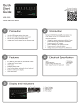
1 Overview
The DSV3 is a family of mobile hand-held biometric
terminal products designed for a wide-range of
identification and ID management applications. The
DSV3 is able to read a wide variety of credentials
containing biometric data, and to compare this
information with the biometric data collected by its on-
board biometrics sensors (fingerprint and cameras). It
allows an operator to capture biometrics and to perform
quick, remote ID verification or identification while in
the field. The DSV3 can operate totally standalone, or it
can coordinate with centralized systems via a rich set of
communications interfaces. It is available with remote
communications capabilities that include: 802.11/WiFi,
Bluetooth, and GSM mobile cellular.
Operators can acquire a fingerprint image and remotely
perform 1-to-many identifications against a watch list, or
perform 1-to-1 comparisons for identity verification.
Superior matching accuracy is achieved through AFIS-quality biometric matching algorithms and rugged
biometric sensors.
The DSV3 mobile terminal is a rugged and environmentally sealed unit that can be used in harsh and
hostile environments. It is shock resistant (Mil STD 810 compliant) and can withstand a fall of four feet
to a concrete surface. The DSV3 mobile terminal exceeds IP 54 specifications for resistance to dust and
water.
The DSV3 is an open platform that comes with a powerful software programming SDK (Software
Developer Kit) that enables customers and system integrators to readily customize the unit for specific
applications and missions. Industry standard interfaces and technologies are used extensively to facilitate
the integration with other systems and to expedite the delivery best of breed solutions to the market. This
approach allows customers to select the technologies and components that are the most appropriate for
their applications and environments.
The flexibility and ruggedness of the DSV3 make it an ideal solution for ID verification and ID
management projects in markets and applications such as:
• Homeland Security • Immigration Control
• Law Enforcement • Airports
• Military Bases and
Ships
• Transportation
• Travel & Border Control • Financial Institutions
• Seaports • Schools and Universities
Figure 1: DSV3-SP Mobile Terminal

44208-00006-000 DSV3-SP User’s Manual Rev 0B
2/12/2009
6
Copyright © 2009 by Datastrip, Inc. All rights reserved.
Reproduction in whole or in part is prohibited.
2 Unpacking & Inventory
Depending on the number of terminals ordered, your
DSV3
units and accessories may be shipped in either
a single-pack box or a multi pack-box. Carefully open the shipping box and use the following Shipping
Box Inventory list to verify the contents.
Shipping Box Inventory:
• DSV3 Mobile Biometric Terminal
• Universal (90-240 VAC input) DC power/charging adapter.
• AC power cord for DC power/charging adapter. (Plug depends on country of destination)
• Documentation, including: User Manual (on CD), End User License Agreement, and Quick-
Reference Guide.
Please retain the shipping box in the event you need to return your product for service.
3 Initial Setup
• Each unit is shipped with one Lithium Polymer battery installed as shown below.
• It is recommended that you fully charge the internal battery before use to maximize operating time
before recharging is required. The DSV3 contains an integrated charging circuit that allows the
batteries to be charged inside the unit whenever the unit is properly connected to the AC adapter.
• The unit may be operated when connected via the AC adapter, regardless of the charge state of the
internal battery.
Please refer to Section 4.44.4“Battery Charging and Replacement”, for additional instructions and
safety information.

44208-00006-000 DSV3-SP User’s Manual Rev 0B
2/12/2009
7
Copyright © 2009 by Datastrip, Inc. All rights reserved.
Reproduction in whole or in part is prohibited.
4 System Overview
The standard DSV3 product comes from the factory with a Windows CE .NET, Version 5.00 operating
system, software utilities, and some demo and sample applications. When the unit is activated, a standard
Windows CE desktop is presented that allows users to launch demonstration programs. The primary
human interface is the touch screen, stylus, and function keys.
4.1 Powering Up the System and System Startup Sequence
The Power Button is located to the top left of the QWERTY keypad as shown in the diagram below. The
power switch has an adjacent tri-color (red/green/yellow) LED indicator, which identifies whether the
system is on, charging, or running low on battery power (see section 4.2).
• To power on the mobile terminal, press the Power button and hold it down until one beep is heard
(approx 2 seconds). When the button is released, a rising tone (mid tone followed by a higher
frequency tone) is produced. The unit will not boot up if the button is held form more than 15
seconds.
• The unit takes approximately 30 seconds to boot up. The display will indicate that the system is
booting. During this time the BIOS is loaded and diagnostic testing is performed.
• When the unit finishes powering up, the Windows CE.NET desktop will appear on the display.
Ambient Light Sensor
Programmable LED
Status Indicators
Function Buttons Function Buttons
Navigation Button
Power Button
Speaker
Microphone
Power Status LED
Indicator (tri-color)
Fingerprint Sensor

44208-00006-000 DSV3-SP User’s Manual Rev 0B
2/12/2009
8
Copyright © 2009 by Datastrip, Inc. All rights reserved.
Reproduction in whole or in part is prohibited.
4.2 Power Status LED Indicators
Shown below are the states for the Power Status LED Indicator depending on the charge state of the
battery, and whether or not the AC adaptor is connected.
• If red is included in the LED display sequence, this indicates that the battery charge level is very
low or that the battery is charging.
• If yellow is included in the LED display sequence, this indicates that the system is in suspend
mode.
• Note that the LED will be active (very slow blink) even when the unit is powered off. This signals
to the operator that the battery is installed and the unit can be powered up.)
• See section 5.3 for a description of the battery gauge available via WinCE.
• See section 5.3.1 for a description of the available power management states.
External Power
Connected? Battery Charge
State Power Status
LED Color Power Status LED Blink Rate
System Powered Off
no extremely low Red Lit Only When Power Button Pressed
no not low Green Very Slow
no low Red / Green Very Slow with Color Blink
yes no battery Green Very Slow
yes charging Green / Red Continuous with Very Slow Color Blink
yes fully charged Green Very Slow
OS Running
no not low Green Slow
no low Red / Green Continuous with Color Toggle
yes no battery Green Solid
yes charging Green / Red Continuous with Slow Color Blink
yes fully charged Green Solid
System in Suspend Mode
no not low Yellow Slow
no low Red / Yellow Continuous with Color Toggle
yes no battery Yellow Solid
yes charging Yellow / Red Continuous with Slow Color Blink
yes fully charged Yellow Solid
Definitions
• Lit Only When Power Button Pressed: On continuously when Power Button Pressed.
• Very Slow: Mostly dark with quick blink approx every 5 seconds (~1% duty cycle).
• Very Slow with Color Blink: Mostly dark with quick blink approx every 5 seconds. Color
changes while lit from Color 1 to Color 2.
• Continuous with Very Slow Color Blink: LED is On continuously with a 5 sec period, where
color 1 is On for 4.9 sec and color 2 is On for 0.1 sec.
• Continuous with Slow Color Blink: LED is On continuously, with a 2 sec period, where color 1
is On 1.9 sec, and color 2 is On 0.1 sec.
• Slow: LED is On 50% of the time, blinking every 3 seconds (50% duty cycle, 3 sec period).
• Solid: LED is On continuously.
• Continuous with Color Toggle: LED is On continuously, alternating evenly between the two
colors each second.

44208-00006-000 DSV3-SP User’s Manual Rev 0B
2/12/2009
9
Copyright © 2009 by Datastrip, Inc. All rights reserved.
Reproduction in whole or in part is prohibited.
4.3 Power Status Tone Indicators
Unit is Off Tone Type Notes
Button depressed (within 300 ms of press) Beep Signals ok to release button
Button released (0 < x < 15 sec) Rising Tone Start system turn on sequence
Button released (x > 15 sec) Deep Sleep Tone Deep sleep not yet implemented
Unit is On
Power button press to enter suspend mode Blip Tone Signals ok to release button
Button released (0 < x < 2 sec) None Go to suspend mode
Button released (2 < x < 15 sec) Falling Tone Turn off the system
Button released (x > 15 sec) Emergency Shutdown Ungraceful shutdown
WinCE launched Microsoft launch tone Signals the launch of the OS
Battery enters an extremely low state Warning Tone System needs attention
Unit is in Suspend
Power button press to resume Blip Tone Signals ok to release button
Button released (0 < x < 2 sec) None Go to resume mode
Button released (2 < x < 15 sec) Falling Tone Turn off the system
Button released (x > 15 sec) Emergency Shutdown Ungraceful shutdown
Entering off state via power management Falling Tone see section 5.3
Definitions
• Beep: Mid frequency tone
• Rising Tone: Mid followed by a higher frequency tone
• Falling Tone: Mid followed by a lower frequency tone
• Warning Tone: Slightly longer low frequency tone
• Blip Tone: Slightly shorter high frequency tone
• Deep Sleep Tone: ???
4.4 Battery Charging and Replacement
The DSV3 uses one 5000 mAH Lithium Polymer battery pack. Under normal operating conditions, the
battery does not need to be removed. The DSV3 has an internal charging circuit that will charge the
battery whenever the unit is connected to the external AC power adapter.
If the user does want to replace the battery, it may be replaced when the unit is off, or the battery may be
hot swapped when the unit is in Suspend mode. To hot swap the battery, save any work in progress and
put the DSV3 into Suspend by tapping the power button (or via the Suspend command on the Start
Menu). Turn the quick release (quarter-turn) bails on the battery access cover on the rear of the unit.
Remove the old battery and replace it with a charged battery within 30 seconds to prevent the unit from
shutting down. Replace the battery-access cover and re-fasten it by tightening the quick release bails.
Quick Release
Receptacles Quick Release
Bails

44208-00006-000 DSV3-SP User’s Manual Rev 0B
2/12/2009
10
Copyright © 2009 by Datastrip, Inc. All rights reserved.
Reproduction in whole or in part is prohibited.
4.4.1 Battery Capacity and Charging
1. The capacity estimates in the following table are for a healthy new battery and are worse case
results that reflect continuous use with all power saving options turned off. Actual capacity
performance will be much better if the power management features are enabled.
2. The battery capacity (hours of use) can be extended significantly by using the power savings
options such as: System Idle or Suspend. These power settings are user programmable and details
can be found in Section 5.3 Power Management.
3. The charge time is approximately the same whether the battery is charged with the unit “On” or
“Off”.
4. When a DSV3 terminal is left on the shelf in the “Off” state, the battery will maintain its charge for
over 1 month.
Description DSV3-SP Capacity
(hours of use) DSV3-EP Capacity
(hours of use) Charge Time for fully
depleted battery
One 5000 mAH battery 6 hours 5.0 hours 3 hours
There is also an internal, rechargeable coin cell battery that powers the Real Time Clock for more than 6
months while the unit is off. This battery is automatically recharged by the system and does not require
any operator service.
CAUTION! Use ONLY approved replacement batteries and power adapters as provided by Datastrip.
CAUTION! Battery has a risk of FIRE, EXPLOSION, or BURNS. DO NOT: short-circuit the battery
terminals; crush, puncture, disassemble or otherwise damage the battery’s case; operate or charge at
temperatures above 40ºC or store the battery at temperatures above 100ºC; incinerate or immerse in water.
DISPOSAL: Always consult and obey all international, federal, provincial/state, and local hazardous waste
disposal laws. Certain jurisdictions require recycling of this spent product.
4.5 Keypad and Function Buttons
The DSV3 includes a backlit extended QWERTY keypad, and two groups of four backlit function buttons
that are vertically aligned along the left side and right side of the LCD display. These two groups of
function buttons operate identically and are initially programmed as standard “F1” through “F4” keys
(mapped as cursor / arrow keys). The control of the function buttons are exposed in the SDK to allow
system integrators to define their usage in custom software applications.
The Navigation Button is located in the center of the unit just under the LCD display and above the
QWERTY keypad. The Navigation Button is not a mouse control; however, it allows an operator to
navigate through menus and select menu items.

44208-00006-000 DSV3-SP User’s Manual Rev 0B
2/12/2009
11
Copyright © 2009 by Datastrip, Inc. All rights reserved.
Reproduction in whole or in part is prohibited.
4.6 Software Input Panel / Keyboard
The DSV3 has both an extended QWERTY keyboard and a
Virtual Input Keyboard (Software Input Panel) that can be
used to enter alpha-numeric information. Tap the Software
Input Panel icon in the bottom right hand corner of the
screen to show or hide the Virtual Input Keyboard / Software
Input Panel.
4.7 LCD Display & Touch Screen
The LCD is a color-TFT (Thin Film Transistor) active-matrix display, and features white-LED
backlighting. There is a resistive touch panel overlay, which should only be operated with the included
stylus to help prevent scratching or other damage.
4.8 Fingerprint Sensor
4.8.1 Fingerprint Sensor –NIST FIPS 201/SP 800-76 Compliant
The integrated fingerprint sensor is an 8-bit, grayscale, solid-state, capacitive-touch device that can
capture fingerprint bitmap images measuring 256 pixels wide by 360 pixels high at 508 dpi. Images from
this sensor can be used for a variety of card holder ID validation purposes, including matching, storage,
and extraction of fingerprint minutia templates.
The DSV3 mobile terminal is compliant with fingerprint matching algorithms from a variety of the
industry leading vendors such as: Identix, Cogent, Bioscrypt, Motorola, and NEC. However, the Identix
algorithm is the only algorithm directly available from Datastrip for the DSV3 terminal at this time.
4.8.2 Fingerprint Sensor Calibration
The fingerprint sensor is factory calibrated and tested on every DSV3 terminal, however, if recalibration
is required for some reason, follow these steps:
• Double tap My Computer and Select Storage Card / DSVII.
• Double tap the PPCalFt41utility and press the “Calibrate” button to re-calibrate the fingerprint
sensor. This process may take up to a minute and then a “green” window with a number “1”
should appear to indicate the sensor was successfully calibrated.
• Double tap the DsVerifyFpCaptureTest application. In the lower right hand corner select “UPEK”
and click “OK”.
• Use the “Scan” button to test the fingerprint image quality.
4.8.3 Finger Placement Guidelines
It is important to place the finger properly on the sensing area to enable the DSV3 to more quickly capture
a good fingerprint image. Listed below are the guidelines for proper finger placement.
• Finger placement icons: These two icons pictorially indicate the correct (green) and incorrect
(red) way to align the cuticle of your finger with the points of the finger-placement guide arrows.
• Finger placement guide arrows: These arrows should be used as a guide for alignment of the
cuticle part of the finger as described above.
Software Input Panel Icon

44208-00006-000 DSV3-SP User’s Manual Rev 0B
2/12/2009
12
Copyright © 2009 by Datastrip, Inc. All rights reserved.
Reproduction in whole or in part is prohibited.
4.9 Cleaning the LCD Touch Screen and Fingerprint Sensor
The LCD touch screen and fingerprint sensor require periodic cleaning to remove dirt, oils, grease, dust,
and foreign matter.
• Ensure that the DSV3 power is OFF and unplugged from any external power source.
• Using standard alcohol wipes, gently wipe the surface of the LCD screen and fingerprint sensor
until it appears clear.
• Allow the cleaning solvent to dry completely before turning the unit on again.
4.10 I/O Port Access
The top rubber end cap on the DSV3 snaps open to reveal the CFIO, SDIO, and onboard wired I/O ports.
To open the top rubber end cap, pull up from the back edge using the two finger indents. The rubber cap
is tethered at two points to prevent it from being lost or misplaced. To close the cover, simply press the
cover into place.
Shown below is the I/O connector panel located on the top of the unit. It contains one mini-USB host
port, one mini-USB client port, one external Compact Flash (CFIO) slot, one Secure Digital module
(SDIO) slot, and the Audio Headset jack.
4.10.1 USB Ports
There is one USB Host port and one USB client port on the DSV3 mobile terminal that are accessible
under the rubber I/O port cover. These are USB 2.0 High Speed (480 Mbps) ports; however, they are also
backwards compatible with USB 1.1 Full Speed (12 Mbps) and Low Speed (1.5 Mbps). Additional USB
ports are available on the DSV3 Docking Station (see section 12).
The USB Host port is used to connect with USB peripheral devices such as a keyboard, a mouse, or flash
memory drives.
The USB Client port enables the DSV3 mobile terminal to connect and communicate with devices such as
PCs and servers using Active Sync. The USB Client port on the top of the DSV3 is disabled when the
unit is placed in the docking station. There is an alternate USB Client port available on the docking
station for use during this situation.
4.10.2 Compact Flash (CFIO) Slot
The DSV3 has a Type-I/II Compact Flash slot that is accessible under the rubber I/O port cover. It is
compatible with a range of CF memory and peripheral devices.
4.10.3 Secure Digital Memory Card (SDIO) Slot
The DSV3 has a SD slot that is accessible under the rubber I/O port cover. It is optimized (recessed) for
Datastrip’s 802.11 peripheral; however, it is a standard SD slot, so a range of SD memory and SDIO
peripheral devices may be used.
Compact Flash / CFIO
USB Host Port
Secure Digital / SDIO
Audio Headset Jack
US
B
C
li
e
nt P
o
rt

44208-00006-000 DSV3-SP User’s Manual Rev 0B
2/12/2009
13
Copyright © 2009 by Datastrip, Inc. All rights reserved.
Reproduction in whole or in part is prohibited.
4.10.4 Audio Headset Jack
The audio headset jack is a 2.5 mm jack that supports stereo headset and microphone.
4.11 Contactless Smart Card Reader
The DSV3 has an integrated Contactless
Smart Card reader subsystem (transceiver
and antenna). The antenna is positioned
around the QWERTY keypad as shown
below. Place the smart card to be read in
the center of the antenna for the best read
performance. The typical operating range is
at least 30 mm.
4.12 Digital Still Camera Peripheral Module
The Digital Still Camera (DSC) is an optional
module for the DSV3 mobile terminals. It is a 3.2
Megapixel camera that can be installed in the
Integrated Peripheral bay. The DSC is designed
for use in a variety of applications and markets
such as facial recognition, law enforcement,
mobile enrollment, and other scenarios.
4.12.1 Digital Still Camera Installation Instructions
To install the digital still camera (DSC) peripheral in the integrated peripheral bay:
Step 1: Remove the cover to the integrated
peripheral bay by removing the 2 Philips-head
screws.
Step 2: Remove (unscrew) the rubber stylus
holder from the old bay door, and fasten
(screw) it to the rear of the mobile terminal.
Smart Card
Antenna
Location
Stylus Holder
& Screws
Screws
Ground
Right
Left Micro
p
hone
Digital Still
Camera Module

44208-00006-000 DSV3-SP User’s Manual Rev 0B
2/12/2009
14
Copyright © 2009 by Datastrip, Inc. All rights reserved.
Reproduction in whole or in part is prohibited.
Step 3: Align the connector on the camera
peripheral module with the edge connector in
the bay and gently press the camera module
into place.
Step 4: Secure the module by re-fastening
the 2 Philips-head screws.
4.13 Point & Shoot Scanner Peripheral Module
The Point & Shoot Scanner is an optional module for the DSV3 mobile terminals. It is a 1.1 Megapixel
camera that provides high resolution scanning (image capture) for decoding numerous optical
symbologies. It contains enhanced scanning and decoding algorithms and can decode all standard 1
dimensional and common 2 dimensional barcodes. The point & shoot design combined with a wide
angled lens that covers a large scanning area provides quick and easy targeting. There is a comprehensive
SDK that enables rapid custom application development.
The Point & Shoot Scanner is designed for a variety of applications and markets such as:
• Law Enforcement / Public Safety
• Military Base Security / Border Control
• Government / Military ID Processing
• Seaport Security and Access Control
• Emergency First Responders
The supported optical symbologies are listed below:
1D Codes 2D Codes OCR
Code 39 PDF417 (standard) OCR A (optional)
Code 93 QR Code (optional) OCR B (optional)
Code 128 Data Matrix (optional) MICR (optional)
UPC/EAN/JAN Aztec Code (optional)
Hong Kong 2 of 5 Maxicode (optional)
Interleaved 2 of 5 Micro QR Code (optional)
NEC 2 of 5 Codeblock (optional)
Matrix 2 of 5 Composite Code (optional)
Straight 2 of 5
Code 11
Codabar
MSI Plessey
Pharmacode
DataBarTM
4.13.1 Point & Shoot Scanner Installation Instructions
To install the Point & Shoot Scanner peripheral in the integrated peripheral bay, follow the same steps as
for the Digital Still Camera (DSC) peripheral module (see section 4.12.1).
Screws
Edge
Connector

44208-00006-000 DSV3-SP User’s Manual Rev 0B
2/12/2009
15
Copyright © 2009 by Datastrip, Inc. All rights reserved.
Reproduction in whole or in part is prohibited.
5 Basic Operation
The following sections describe some of the features and functions that are available on the DSV3 family
of products.
5.1 Stylus Usage
The DSV3 provides a stylus to use with the touch screen for selecting items and entering information (the
unit may also be operated with a standard USB mouse). The DSV3 stylus can be found in the stylus
holder on the back of the DSV3-SP and the front of the unit the DSV3-EP. The following actions are
available with the stylus:
• Tap: Lightly touch the screen once with the stylus to select an object. Tapping is equivalent to
clicking an item with the mouse on your personnel computer.
• Double-Tap: Lightly touch the screen twice with the stylus to open folders and applications.
Double-Tapping is equivalent to Double-clicking an item with the mouse on your personnel
computer.
• Drag: Hold the stylus on the screen and drag it across the screen to select text and images. Drag
within a list to select multiple items.
• Tap-and-hold: Tap and hold the stylus on an item for a short period until a menu displays a list of
actions available for that item. Tapping and holding is equivalent to right-clicking your personnel
computer mouse button. When you tap and hold, a circle of red dots appears around the stylus to
indicate that the menu will soon pop up. Tap the action you want to perform on the pop-up menu
that appears.
5.2 Touch Screen Adjustments
The touch screen on DSV3 terminals is calibrated during factory acceptance tests. If you wish to
recalibrate these setting to suit your personnel preferences, the following options are available:
• Calibration: If your device is not responding properly to your screen taps, you may need to
recalibrate your screen. Go to the Control Panel, select Stylus Properties and under the
“Calibration” tab, click the “Recalibrate” button and follow the on screen instructions. When you
are told to “press enter” to accept the setting, just tap the screen anywhere, then click the “OK”
button.
• Double-Click Sensitivity: Go to the Control Panel and select Stylus Properties. Double–tap the
checkerboard grid to set the double-tap sensitivity for both speed and physical distance between
the taps. Then double tap the icon below the checkerboard to verify your settings. Click the “OK”
button when done.
• Brightness and Contrast: The display brightness and contrast can be adjusted for different
operating environment lighting conditions. Go to the Control Panel, select Display and under the
“Backlight” tab adjust the slider control then click the “OK” button.
5.3 Power Management
The DSV3 Power Properties can be configured and monitored by double clicking the Power icon in the
WinCE Control Panel. The Battery Tab displays the battery gauge / charge status, and the Schemes Tab
allows the user to configure the timeout for each of the Power States defined below.
5.3.1 Power Management States
Clicking the Schemes tab allows you to configure when the system enters into the various power
management modes available to maximize battery life. You can configure the time the system must be
idle before entering each of the available power management states.
Note: The times configured by the user for each state are cumulative! For example, the time required
for the system to suspend is the sum of the time configured to go to User Idle + the time to go to System
Idle + the time to go to Suspend.

44208-00006-000 DSV3-SP User’s Manual Rev 0B
2/12/2009
16
Copyright © 2009 by Datastrip, Inc. All rights reserved.
Reproduction in whole or in part is prohibited.
The power management states are:
• Fully On
Every subsystem in the mobile terminal is on and operational
• User Idle
This state is entered when the touch screen or function keys have not been used for some
amount of time (user configurable).
The backlight is dimmed to save power.
All other internal subsystems are on.
Tap the screen or give the power button a quick tap to wake up the unit to a Fully On
condition.
• System Idle
This state is entered when no major background software tasks are running and the touch
screen or function keys have not been used for some amount of time (user configurable).
In this state, the backlight is dimmed to save power.
All other internal subsystems are on.
Tap the screen or give the power button a quick tap to wake up the unit to a fully on
condition.
• Suspend
This state is entered when no major background software tasks are running and the touch
screen or function keys have not been used for some amount of time (user configurable).
Suspend mode is indicated by flashing power LED Indicator (see section 4.2).
In this state, the LCD is turned off and backlight is turned off.
USB subsystem is turned off.
CF cards are turned off.
The Processor is put in low power sleep mode.
Tap the screen or give the power button a quick tap to wake up the unit to a fully on
condition.
• Fully Off
Everything in the system is off (except the embedded controller).
Push the power button to start the unit and return to a Fully On state.

44208-00006-000 DSV3-SP User’s Manual Rev 0B
2/12/2009
17
Copyright © 2009 by Datastrip, Inc. All rights reserved.
Reproduction in whole or in part is prohibited.
5.4 Battery Gauge
A battery gauge is available in the Control Panel under Power Properties. It provides information about
the about the battery charge level and charging status. Clicking the Battery tab displays the DSV3 battery
gauge. The battery charge level (percentage power remaining) is shown at the bottom of the Power
Properties / Battery tab window.
5.4.1 Charging States
The Power Properties / Battery tab window also shows that state of the internal battery charger. There are
three charging states.
• Main Battery: The terminal is operating on battery power and no external AC adapter is
connected.
• External: External AC adapter is connected and the battery is fully charged.
• Charging: External AC adapter is connected and the battery is charging. The unit operates
normally while simultaneously charging the battery.
5.4.2 Battery Charge Level States
The charge level state of the battery is also listed in the Power Properties / Battery tab window. There are
three charge level states. When the battery gauge is “Very Low”, the battery should be immediately
charged by connecting the unit to an AC adapter or the unit will automatically shut down when the
voltage level drops below the minimum threshold.
• Good: Battery charge is Good
• Low: Battery charge is Low (<10% remaining)
• Very Low: Battery charge is Very Low / Critical (<5% remaining)
5.4.3 Other Indicators
There are three user warnings that occur when the battery level is “Very Low”: See section 4.2 and
section 4.3 for the LED and tone indicator states that also provide user feedback regarding battery charge
levels and charging states.
• The power LED alternately flashes Red and Green (see section 4.2)
• A “Warning” message pops up “Main Battery Very Low”. This warning will repeat itself
periodically until the condition clears or the unit automatically shuts down.
• An error beep sounds when the battery charge level is critical.
Charging State
Battery Charge
Level Summary
Battery Charge Level

44208-00006-000 DSV3-SP User’s Manual Rev 0B
2/12/2009
18
Copyright © 2009 by Datastrip, Inc. All rights reserved.
Reproduction in whole or in part is prohibited.
5.5 Creating Desktop Shortcuts
Find the application for which you want to create a shortcut. Tap and hold the stylus on the application
until the options menu pops up. Select copy and go to the directory where you want to put the shortcut.
Tap and hold the stylus until the options menu pops up and select “Paste Shortcut”.
5.6 Safe Boot Mode
The DSV3 provides a mechanism that permits the recovery of lost or damaged
operating system files via a “Safe Boot” mode. This mechanism is similar to
Microsoft Windows Safe Mode that is available on PCs. If one or more
operating system files have been damaged or inadvertently deleted, when the
unit is turned on it will automatically boot-up into a smaller, limited function
version of Windows CE that will permit the recovery of the files or allow them
to be replaced or overwritten. This permits the unit to be repaired, and then
subsequently rebooted using the full version of Windows CE. Safe Boot mode
can also be accessed on demand by holding down the F1 key while turning on
the power to the unit. A special bitmap will appear indicating that the unit is
booting-up in Safe Boot mode.
6 Software Utilities
All of the utilities listed below except “DsVerify2About” are located in the “\My Device\Hard
Disk\DSV3” directory. The “DsVerify2About” is a hidden file in the Windows directory. There are
additional demonstration programs available as source code for custom software development in the
Datastrip MT SDK (sold separately).
6.1 Software Version Utility (DatastripDSVerify2About.exe)
This utility reports the Operating System (OS) Version, the versions of all
Datastrip specific drivers and components, software license settings, the unit
serial number, and the HW Configuration. To run this utility:
• Click Start \ Run
• Click Browse then Double tap the Windows folder
• Scroll over and double tap the application: DatastripDsVerify2About.exe
• Click “OK”
This version information can be saved to a file by clicking on the “Send to File”
button.
6.2 DsVerify Registry Install Utility (DsVerifyRegInst.exe)
This application registers all of the Datastrip specific components of the DSV3 that are needed to
read/write Smart Cards, scan documents, operate the Fingerprint sensor, and so forth. It is typically run
after a software update to register the components in sequence, and it reports any errors if it does not
succeed. If it finishes successfully, there will be a pop-up message box indicating “Finished
Registration”. It can take up to a minute or two to complete this process.
Internally, this program calls regsvrce.exe to register each ActiveX control so that the interface
presented by the ActiveX control will be available for application use. This is usually followed by
RegistrySaver.exe (or Suspend) to make sure that the altered registry is written to flash memory for
future use. When this application is invoked, it queries the user for the specific mobile terminal type
(DSVII-SC, DSVII-SW, DSVII-PA, DSV3-SP, or DSV3-EP) and writes the appropriate platform type
information into the registry along with the other registration information.

44208-00006-000 DSV3-SP User’s Manual Rev 0B
2/12/2009
19
Copyright © 2009 by Datastrip, Inc. All rights reserved.
Reproduction in whole or in part is prohibited.
6.3 DsVerify Registry Saver Utility (RegistrySaver.exe)
This application is used to save the current registry settings to flash memory. This is very useful after
adding applications (or applications components such as ActiveX controls) to DSV3 products that require
some aspect of the behavior to be registered. When the DSV3 terminal is powered-on, the saved registry
is read and used as part of WinCE startup. Datastrip ActiveX components are registered (see
DsVerifyRegInst application) and then the registry settings are saved using this application. The registry
can also be saved by hitting “Suspend” function that is located under the Start menu button, but this
application is provided to save the registry to the Storage Card without having to warm-start the unit.
6.4 Fingerprint Capture Utility (DsVerifyFpCaptureTest.exe)
This application demonstrates the capabilities of the fingerprint image sensor on the DSV3, and it
provides a means of exercising the fingerprint imaging system. The application has several buttons that
allow a user to Scan to the display or Scan to File. Since this application is provided as source code in the
SDK, it is often used as an example for developers to observe how typical application software can
interface to the fingerprint subsystem. The source code for this application is provided in the SDK for
developer use.
7 Loading Software and Firmware
7.1 Loading DSV3 Software Updates
The DsVerify2SoftwareUpdate application permits the user to download software updates from several
source locations are as list below:
• CAB files located on a CF memory card: call Storage Card
• CAB files located on a USB flash drive: call Hard Disk 2
• CAB files loaded from an FTP server, (requires a username and password to a valid account.
7.1.1 DSV3 Software Update Procedure: Using a CF Card
NOTE: It is recommended that upgrades be done with the unit operating on the AC adapter to ensure that
the unit does not lose power during this procedure. This upgrade process should take approximately 3.5
minutes to complete.
• Insert the CF Card containing the new CAB file into the external CF slot.
• Power up the DSV3 terminal.
• When the device is finished booting, double tap My Device and select Hard Disk \ DSV3.
• Double tap the DsVerify2SoftwareUpdate utility.
• Scroll through the options on the Server scroll box and select the Storage Card entry (you must
scroll down to make selection).
• Username and Password are not necessary for this procedure
• Select most recent appropriate source file
• Click Update (This step will take approximately 2.5 minutes.
• Click Reboot (The registry will be cleared prior to shutdown).
• Power up the unit
• The DSV3 registration program will automatically open. Select the button for the device that you
are registering (DSV3-SP or DSV3-EP). Select [OK] and wait. (This process will take a few
seconds).
• Click [Ok] in the “Hurray!” box when it appears, then close the application window.
• Double tap My Device and select Hard Disk \ DSV3.
• Double tap the Registry Saver program (RegistrySaver.exe) to launch it.
/