Page is loading ...

INSTALLATION INSTRUCTIONS
Item# P5561-066-L (New. 2023/02/02)
READ AND SAVE THESE INSTRUCTIONS
WA R N I N G ! S H U T P O W E R O F F AT F U S E O R C I R C U I T B R E A K E R .
AVERTISSEMENT! COUPER LE COURANT AU NIVEAU DES FUSIBLES OU DU DISJONCTEUR.
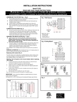
Fig. 1
Fig. 2
Fig. 3
Fig. 4
ASSEMBLING THE FIXTURE (Fig.1)
1 Shut off power at the fuse box or circuit breaker. If necessary,
remove the old fixture including the mounting hardware.
2 Carefully remove the fixture from the carton and check that all
parts are included as show in Figure 1.
3 Unscrew screws (C) and rubber washers (P). Separate
mounting plate (A) from fixture (D).
4 Attach mounting plate (A) to the junction box (not included) with
junction box screws (B) (size: 8-32*1/2”L). The side of the
mounting plate (A) marked “GND” must be face out.
CONNECTION THE WIRES (Fig. 2)
5 Connect the electrical wires as shown in Fig.2, making sure
that all wire connectors are secured. If your junction box has a
ground wire (green or bare copper), connect the fixture's
ground wire to it. Otherwise, connect the fixture's ground wire
directly to mounting plate (A) using the green screw provided.
Tuck the wire connections neatly into the junction box.
FINISHING THE INSTALLATION (Fig. 1)
6 Align fixture (D) onto mounting plate (A) and secure with
screws (C) and rubber washers (P) provided.
7 To prevent moisture from entering the junction box and causing
a short circuit, use clear caulking (i.e. Indoor/Outdoor silicone
sealant) to outline the outside of fixture (D) where it meets the
wall leaving a space at bottom to allow moisture a means to
escape (Fig.3).
Your installation is now complete. Return power to the junction box
and test the fixture.
CAUTION /ATTENTION: When handling the fixture, do not apply
pressure to the LED. Hold the fixture by the base or back plate only.
Replacing LED module (Fig. 4)
The LED module can be replaced by a qualified electrician without
cutting of wire and without damage to any decorative element to
which the fixture is attached. See installation steps for more details
(Fig. 4)
Warning: Turn off power at the circuit breaker before
replacing LED module.
a. To remove the fixture from the wall, loosen screws (C) and
rubber washers (P). Remove the wire connectors and place the
fixture on a clear flat surface (Fig.1).
b. Loosen screws (E) to separate lamp body (O) and glass shade
(N).
c. Loosen screws (M), remove rubber washers (L), and hex nuts
(F) to separate glass panel (K) from LED housing (H).
d. Loosen screws (J) and hex nuts (G) and carefully remove LED
module (I) from LED housing (H).
e. Reverse steps a-d for installing the new LED module.
Note: The LED module should be provided b
y a
specified supplier.
FIXTURE
WIRES
Black or
Smooth
HOUSE
WIRES
Black
(Hot)
FIXTURE
WIRES
White or
Ribbed
HOUSE
WIRES
White
(Neutral)
FIXTURE
WIRES
Green or
Bare
Copper
(Ground)
HOUSE
WIRES
Green
(Ground)
Set
#
A
-
021
-
295112
- Mounting Plate
- Ground Screw
-
Mounting
Screw
*
2
IMPORTANT: Fixture should be installed by a qualified electrician
to ensure proper wiring and installation.
Dimmable with ELV and/or LED compatible wall dimmer
switches
.
LA-3601E
O
N
M
L
K
J
I
H
G
E
F
O
A
B
C
D
P
/