
Junction Box
Fig.5
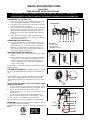
INSTALLATION INSTRUCTIONS
Item# P1229
READ AND SAVE THESE INSTRUCTIONS
W A R N I N G ! S H U T P O W E R O F F AT F U S E O R C I R C U I T B R E A K E R .
AVERTISSEMENT! COUPER LE COURANT AU NIVEAU DES FUSIBLES OU DU DISJONCTEUR.
Fig. 1
Fig. 2
Fig. 3
Fig. 4
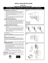
ASSEMBLING THE FIXTURE (Fig.1)
1 Shut off power at the fuse box or circuit breaker. If necessary,
remove the old fixture including the mounting hardware.
2 Carefully remove the fixture from the carton and check that all
parts are included as show in Figure 1.
3 Thread screws (A) into the pre-drilled holes in the circular strap
(B) spaced the same distance apart as the holes in the back
plate of the fixture body and secure with hex nuts (D). The
length of screws (A) into circular strap (B) may be adjusted if
necessary.
4 Attach circular strap (B) to the junction box with mounting
screws (C) (size: #8-32N*L0.5”). The side of circular strap (B)
marked “GND” must face out.
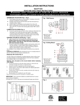
CONNECTION THE WIRES (Fig. 2)
5 Connect the electrical wires as shown in Fig.2, making sure
that all wire nuts are secured. If your outlet has a ground wire
(green or bare copper), connect the fixture's ground Wire to it.
Otherwise, connect the fixture's ground wire directly to the
circular strap using the green screw provided. Tuck the wire
connections neatly into the junction box.
FINISHING THE INSTALLATION (Fig. 1)
6 Align back plate (E) onto circular strap (B), and secure with ball
nuts (F).
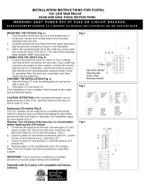
7 To prevent moisture from entering the outlet box and causing a
short circuit, use clear caulking (i.e. Indoor/Outdoor silicone
sealant) to outline the outside of fixture back plate where it
meets the wall leaving a space at bottom to allow moisture a
means to escape (Fig.3).
Your installation is now complete. Return power to the junction box
and test the fixture.
CAUTION /ATTENTION:
When handling the fixture, do not apply
pressure to the LED. Hold the fixture by the base or back plate (E)
only.
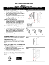
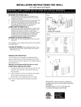
Replacing LED module (Fig. 4)
The LED module can be replaced by a qualified electrician without
cutting of wire and without damage to any decorative element to
which the fixture is attached. See installation steps for more details
(Fig. 4)
Warning: Turn off power at the circuit breaker before
replacing LED module.
a. To remove the fixture from the wall, loosen ball nuts (F), remove
the wire connectors and place the fixture on a clear flat surface.
b. Remove glass shade (M) from fixture (G) by turning
counter-clockwise. Loosen screws (L) to separate LED cover (K)
from fixture (G).
c. Loosen screws (J). Carefully remove LED module (I) and
disconnect quick plug (H) to remove LED module (I). Fig.4
d. Reverse steps a-c for installing the new LED module.
Note: The LED module should be provided by a specified supplier.
FIXTURE
WIRES
Black or
Smooth
HOUSE
WIRES
Black
(Hot)
FIXTURE
WIRES
White or
Ribbed
HOUSE
WIRES
White
(Neutral)
FIXTURE
WIRES
Green or
Bare
Copper
(Ground)
HOUSE
WIRES
Green
(Ground)
Set
#
A
-
020
- Circular Strap
- Ground Screw
-
Mounting
Screw
*
2
IMPORTANT:
Fixture should be installed by a qualified electrician
to ensure proper wiring and installation.
Dimmable with C-L (CFL & LED) type and Incandescent/Halogen type
dimmers
-
 1
1

Ask a question and I''ll find the answer in the document
Finding information in a document is now easier with AI
Related papers
-
 George Kovacs P1200-615C-L User manual
-
 George Kovacs P1070-657-L User manual
-
George Kovacs P5042-647B User manual
-
George Kovacs P1221-287-L User manual
-
-
 George Kovacs P1227-564-L User manual
-
 George Kovacs P1228-564-L User manual
-
George Kovacs P1209-615C-L User manual
-
George Kovacs P5219-077-L User manual
-
 George Kovacs P1203-287-L User manual


Other documents
-
 Minka Lavery 2931-84-L Operating instructions
-
The Great Outdoors 8101-A138 User manual
-
-
Minka Group 6460-84 User manual
-
Minka Group 2257-613 User manual
-
-
-
