Chloride Edge-Glo Edge-Lit Exit Install Instructions

Type
Install Instructions

Chloride Edge-Glo Edge-Lit Exit is a high-quality lighting solution designed for indoor use, providing clear and visible exit signs in various emergency situations. It features a protective cardboard insert to prevent damage during shipment and easy installation with appropriate connectors and a knockout plate for access to wiring. The fixture is equipped with push-on wire connectors, hanger brackets, and torsion springs to facilitate installation and ensure secure mounting. It is suitable for dry, indoor applications and requires a 24-hour circuit of the correct rated voltage.

Chloride Edge-Glo Edge-Lit Exit is a high-quality lighting solution designed for indoor use, providing clear and visible exit signs in various emergency situations. It features a protective cardboard insert to prevent damage during shipment and easy installation with appropriate connectors and a knockout plate for access to wiring. The fixture is equipped with push-on wire connectors, hanger brackets, and torsion springs to facilitate installation and ensure secure mounting. It is suitable for dry, indoor applications and requires a 24-hour circuit of the correct rated voltage.

IN STRUC TION SHEET
RGLO EDGE-GLO EXIT
ALKCO where qual ity co mes to light™
1500 Melrose Av e nue, P.O. Box 1389
Frank lin Park, IL 60131-8389
A Di vi sion of JJI Lighting Group, Inc.
CAU TION — READ AND FOL LOW
ALL SAFETY IN STRUC TIONS
Care fully read the in struc tions ap pro pri ate
to your fix ture. IF YOU HAVE ANY QUES -
TIONS RE GARDING THE PROPER IN STAL -
LA TION OR LO CAL CODES, CON SULT A
QUAL IFIED ELEC TRI CIAN.
To avoid shock haz ard do not work with live
elec tri cal wires.
In stall fix ture in dry, in door ap pli ca tions
only. Do not in stall in ap pli ca tions other than
in tended use.
In stall and wire fix ture in lo ca tions and at
heights in ac cor dance with na tional, state,
and lo cal codes.
En sure that sup ply is a 24-hour cir cuit of cor -
rect rated volt age.
SAVE THESE IN STRUC TIONS
MOUNTING IN STRUC TIONS
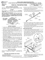
Fig ure 1 pro vides an over all view of the fix ture and
shows all the crit i cal di men sions. Re fer to this il lus tra -
tion as you mount the fix ture.
1. Re move Edge-Glo Exit fix ture and hard ware from
the box. In spect con tents to en sure that no dam age
oc curred dur ing ship ment.
NOTE: The fix ture is shipped with a pro tec tive card -
board in sert in the hous ing. DO NOT RE -
MOVE in sert un til the exit panel is in stalled.
2. Tap the knock out in the ac cess plate so that it can
be re moved.
3. Loosen, but do not re move the screw that at ta ches
the ac cess plate to the top of the hous ing and re -
move the plate.
4. Re move the knock out from the plate.
Figure 1
WARNING: Be cer tain that power is turned off
be fore con nect ing fix ture to sup -
ply lines.
5. Using an ap pro pri ate con nec tor, at tach the ac cess
plate to the sup ply con duit.
6. Using the hous ing as a tem plate, cut the re quired
open ing in the ceil ing panel, and put the panel in
place.
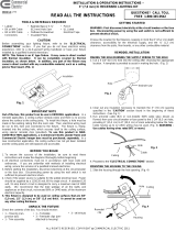
7. Re fer to Fig ure 2 to ori ent the hanger bars prop erly,
and slide them through the brack ets.
8. Using pli ers, bend the tabs clos est to the ends of
the bars out ward so that the T-Bars will fit into the
notches.
9. Lift the as sem bly in place, mak ing sure that the
hanger bars are par al lel to the 2-foot grid, and place
the four notches over the T-Bars to hang the fix ture.
10. Using pli ers, bend the tabs on the hanger bars back
in place to se cure the fix ture to the T-Bars.
NOTE: If the fix ture has a bat tery back-up, there will
be two black wires and two red wires be sides
the ac wires. DO NOT CON NECT THEM AT
THIS TIME.
11. Re fer to Fig ure 3. Using the push-on wire con nec -
tors, con nect the ac wires from the hous ing to the
in com ing ac feed. Con nect black wire to 120 V sup -
ply, (or ange wire to 277 V sup ply), the white wire
(neu tral) to white, and the green wire (ground) to
green. Make sure that the wires are se cure and that
no bare wire is ex posed.
12. Feed the ac wires into the hous ing.
13. Check the po si tion of the hous ing with re spect to
the ceil ing tile grid. If ver ti cal ad just ments are
needed, slightly loosen the wing nuts se cur ing the
hanger brack ets. Make the nec es sary ad just ments
and tighten the wing nuts. The fix ture may be slid
along the hanger bracket to po si tion it prop erly.
14. To in stall the Exit panel, squeeze the ends of each
tor sion spring to gether and in sert the ends into the
slots in the wireway cover. Slowly re lease the
springs, mak ing sure that they stay in the slots.
Care fully push the panel in place.
15. En er gize the ac cir cuit and en sure that the fix ture
lights. If the fix ture does not have a bat tery back-up,
pro ceed to step 18.
16. Con nect the two black dc wires to gether, and then
the two red dc wires.
17. Feed the dc wires into the hous ing.
18. Place the large part of the key hole in the ac cess
plate over the screw clos est to the end of the hous -
ing.
19. Slide the ac cess plate in place and tighten the two
screws.
Figure 2
ALKCO where qual ity co mes to light™
1500 Melrose Av e nue, P.O. Box 1389
Frank lin Park, IL 60131-8389
A Di vi sion of JJI Lighting Group, Inc.
075-0136 5/00
Figure 3
  • Page 1 1
  • Page 2 2

Chloride Edge-Glo Edge-Lit Exit Install Instructions

Type
Install Instructions

Chloride Edge-Glo Edge-Lit Exit is a high-quality lighting solution designed for indoor use, providing clear and visible exit signs in various emergency situations. It features a protective cardboard insert to prevent damage during shipment and easy installation with appropriate connectors and a knockout plate for access to wiring. The fixture is equipped with push-on wire connectors, hanger brackets, and torsion springs to facilitate installation and ensure secure mounting. It is suitable for dry, indoor applications and requires a 24-hour circuit of the correct rated voltage.

Ask a question and I''ll find the answer in the document

Finding information in a document is now easier with AI