Chloride Edge-Glo Edge-Lit Exit Install Instructions

Type
Install Instructions

The Chloride Edge-Glo Edge-Lit Exit offers a reliable and energy-efficient lighting solution for indoor applications. Designed for easy retrofitting, it seamlessly replaces the light source in 120/277 volt AC models of Alkco Edge-Glo Exit signs. With its pre-wired LED driver and LED board, installation is simplified, allowing you to upgrade your existing exit sign without replacing the housing or panel.

The Chloride Edge-Glo Edge-Lit Exit offers a reliable and energy-efficient lighting solution for indoor applications. Designed for easy retrofitting, it seamlessly replaces the light source in 120/277 volt AC models of Alkco Edge-Glo Exit signs. With its pre-wired LED driver and LED board, installation is simplified, allowing you to upgrade your existing exit sign without replacing the housing or panel.

INSTALLATION INSTRUCTIONS
Edge-Glo LED Retrot Kit
MODEL: RGLO-LEDWW
CAUTION! – READ THIS FIRST --- IMPORTANT SAFETY INSTRUCTIONS
* Carefully read the instructions pertaining to your xture.
IF YOU HAVE ANY QUESTIONS REGARDING THE
PROPER INSTALLATION OR LOCAL CODES, CONSULT
A QUALIFIED ELECTRICIAN.
* To avoid shock hazard, do not work with live electrical wires.
WARNING: THIS PRODUCT MUST BE INSTALLED IN ACCORDANCE WITH THE APPLICABLE INSTALLATION
CODE BY A PERSON FAMILIAR WITH THE CONSTRUCTION AND OPERATION OF THE PRODUCT
AND THE HAZARDS INVOLVED.
WARNING: RISK OF FIRE, MINIMUM OF 90°C SUPPLY CONDUCTORS. CONSULT A QUALIFIED ELECTRICIAN
TO ENSURE CORRECT BRANCH CIRCUIT CONDUCTOR.
WARNING: TO AVOID SHOCK HAZARD DISCONNECT THE POWER AT THE PANEL BOARD (CIRCUIT BREAKER
BOX) BEFORE BEGINNING INSTALLATION.
A. Installation Instructions
The Edge-Glo LED Retrot Kit (RGLO-LEDWW) can be used
to replace the light source in any 120/277 volt, AC model of Alkco
Edge-Glo Exit sign including models: RGLO-, SGLO- and
WGLO-. The Retrot Kit is designed to easily replace the existing
wireway without having to replace the exit sign housing or panel.
1. Turn off the building power to the existing Exit Sign. Conrm
that the existing Exit Sign is a 120/277 volt, AC model before
proceeding. The RGLO-LEDWW is not suitable for battery
powered models of Exit Signs.
2. Pull down on the Exit Sign panel until the two wire torsion
springs are accessible. Carefully pinch the legs of each
spring together so that the torsion spring can be release
from the sign housing. Once both torsion springs have been
released, set the face panel assembly down being careful
to protect the panel faces. This same face panel assembly
will be reused once the Retrot Kit has been installed. (See
Photo 1).
3. The metal wireway panel is held in place with a screw at
each end of the wireway. Completely remove one of the
screws and loosen the other while supporting the wireway
panel. Once the second screw has been loosened, allow the
free end of the wireway panel to swing down out of the sign
housing and then slide it from under the remaining screw until
it is free from the housing. (See Photo 2).
4. Disconnect the black (hot) and white (neutral) power leads
from the building power leads. Some models of Edge-Glo
Exit Signs may have an orange quick disconnect plug that
can be pulled apart to disconnect the power connections
to the wireway panel.
11500 Melrose Avenue
Franklin Park, Illinois 60131
Phone: 847-451-0700
Fax: 847-451-7512
www.alkco.com
* Install the xture in only dry, indoor applications.
* Do not install outdoors or in applications other than the
intended use.
* Install and wire the xture in locations in compliance with
the National Electric Code and any local codes.
Figure 1
Figure 2
TORSION SPRINGS
SCREW
SCREW
5. Once the existing wireway panel is disconnected and free from the
sign housing, it can be set aside. This wireway will not be reused.
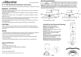
6. Remove the RGLO-LEDWW from the packaging. The LED driver
and LED board are pre-wired onto the metal wireway plate to
simplify the replacement process. The metal wireway plate is
identical in size to the original wireway installed in the product.
(See Photo 3).
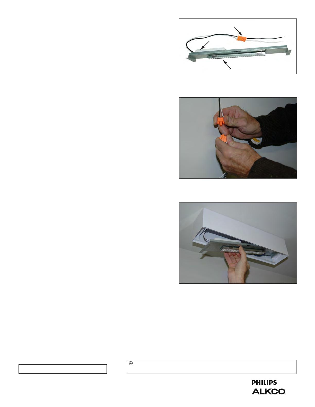
7. Locate the black and white leads coming from the LED driver
and connected to an orange quick disconnect plug. Pull the
quick disconnect plug apart. (See Photo 4). If the existing sign
has a quick disconnect plug, go to step a.) below. If the leads
for the previous wireway panel were connected to the building
power with wire nuts, then go to step b.) below.
a.) Lift the wireway panel for the Retrot Kit up so that
the female side of the orange quick disconnect plug
(connected to the wireway) can plug together with the
male side of the plug wired to the building power within
the sign housing. Continue to Step 8.
b.) Take the free portion of the wireway leads (that were
disconnected in Step 7 above) and connect the black
lead to the building hot lead in the exit housing and the
white lead to the building neutral lead in the exit housing
using wire nuts. Lift the wireway panel for the Retrot Kit
so that the female side of the orange quick disconnect
plug to the male side of the plug that is wired into the
exit housing. Continue to Step 8.
8. Slide the slotted end of the Retrot Kit wireway under the loos-
ened screw in the housing making sure that the side of the
wireway with the LED board is facing toward the room and the
LED driver is tting into the exit housing. (See Photo 5).
9. Swing the other end of the wireway panel up into the sign and
reinstall the screw to retain hold the wireway panel in the sign.
Completely tighten the other loosened screw. The wireway
panel should now be rmly secured within the exit housing.
10. Lift the face panel assembly up to the sign and reinsert the
torsion springs into the housing by pinching the spring legs
together so that the ends can be inserted into the brackets.
Once both springs are engaged, gently push up on the panel
assembly until it draws up to the ceiling, enclosing the housing.
11. Turn the power to the sign back on and verify that the sign
is illuminated.
CUSTOMER SUPPORT
If you require additional information regarding this light xture we invite you to call us at Alkco. Our business hours are: Monday - Friday
(except holidays), 8:00am to 4:30pm Central time. Phone: 847-451-0700, Fax: 847-451-7512
REPLACEMENT PARTS
Contact Alkco Lighting directly for information on replacement parts. When calling, be prepared to provide the model
number and date of manufacture of the xture. This information is indicated on labels located on the product.
.075.0381 05/12 RGLOLED-WW Series
2
Figure 3
Figure 4
Figure 5
QUICK DISCONNECT PLUG
LED BOARD
LED DRIVER
Some luminaires use uorescent or high intensity discharge (HID) lamps that contain small amounts of mercury. Such lamps are
labeled “Contains Mercury” and/or with the symbol “Hg.” Lamps that contain mercury must be disposed of in accordance with local
requirements. Information regarding lamp recycling and disposal can be found at www.lamprecycle.org
  • Page 1 1
  • Page 2 2

Chloride Edge-Glo Edge-Lit Exit Install Instructions

Type
Install Instructions

The Chloride Edge-Glo Edge-Lit Exit offers a reliable and energy-efficient lighting solution for indoor applications. Designed for easy retrofitting, it seamlessly replaces the light source in 120/277 volt AC models of Alkco Edge-Glo Exit signs. With its pre-wired LED driver and LED board, installation is simplified, allowing you to upgrade your existing exit sign without replacing the housing or panel.

Ask a question and I''ll find the answer in the document

Finding information in a document is now easier with AI