GE ZKD910BF2BB Installation guide
- Category
- Warming drawers
- Type
- Installation guide

Installation
Instructions
If you have questions, ca!l 800,6E,CARESor visit ourwebsite at:w.monogram.com
27"and30"
Warming Drawers
Models:
ZKD910
ZTD910
Monogram:

Before you begin - Read these instructions coinpletely and careflllly:
IMPORTANT - Save these instIuctions for local inspector's use.
IMPORTANT - OBSERVE AI,I, GOVERNING CODES AND ORDINANCES.
Note to Installer - Be sure to leave these instiuctions with the Consunler.
Note to Consumer - Keep these instructions with vour Owner's Manual fi)i" fliture reference.
¥!,,,,r..l:_,_llL't_This appliance must be properly grounded. See "Electrical Supply", page 4. [
r!,w,._=l_,_llt.],_mCet appaxeil dolt 8tre correctement mis h la terre. Consulter page 4. [
If wm received a dainaged warining drawei;
w)u should inunediatelv contact w)ur dealer
or builder.
Proper installation is the responsibility of the
installer. Product taihu'e due to inlproper
installation is not covered under the GE
Appliance Warranty. See the Lrse 8.: Care
Guide fl)i" warranty inforination.
• Use this appliance only fi)r its intended
purpose.
Check with local utilities fi)i" electrical codes
that apply in your area. i,ocal codes vary.
Installation electrical connections and
grounding n/ust ctnnply with applical)le codes.
In the absence (if local codes, the drawer
should be installed in accordance with
National Electrical Code ANSI/NFPA 70-1990
or latest edition,
WARNING:
ANTI-TIP PRECAUTIONS
An anti-tip brace must be installed to
prevent the drawer from tipping forward
when opened and loaded. Failure to do so
could result in personal injury.
PRECAUTIONS :
CONTRE LE BASCULEMENT
Pour 6viter les blessures, il faut installer
mae patte de retenue pour empScher le
tiroir de basculer quand il est ouvert et
plein.
For Monogram local service in your area,
1.800.444.1845.
For Monogram service in Canada, call
1.888.880.3030.
For Monogram Parts mid Accessories, call
1.800.626.2002.
Con n
Design Information
Models Available .................................................................................................................................. 3
Product Diinensions ............................................................................................................................ 3
Accessories ........................................................................................................................................... 3
Tools and Materials Required ............................................................................................................ 3
Installation Preparation
Adwmce Planning ............................................................................................................................... 4
Grounding the Appliance ................................................................................................................... 4
ReInove the Packaging and Parts ....................................................................................................... 5
hlstallation Below a Countertop ........................................................................................................ 5
hlstallation Below Wall (-)veils ............................................................................................................ 6
Installation
Step 1: Provide Cabinet Support and Anti-Tip Bracket ................................................................... 7
Step 2: hlstall _4'arining Drawer ......................................................................................................... 7

Design Information
_.:D_rmir_g Drawer
ModeLs
Available.
ZTD910
30" Wide model
ZKD910
27" Wide model
The warming drawers may be installed
directl_ into a wall or wall oxen cabinetry
or beh)w a Cotlntertop,
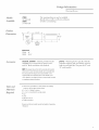
P, oduct
Dimensions
_27'_ 23-1/4"_
',I Drawer 11 I ,
',I Open 9
" 26,,
E , t
10-1/2"
Dimension A
ZTD910 30"
ZKD910 26-3/4"
Accessories
ZXD27B, ZXD30B - This kit provides for the
) c _))
installation of a custom front panel ( n 2 t
and 30" black and white wide models,
NOTE: Theoriginal drawer front will beremovedand discarded
when this kit is used.Thetubular handlecan be reinstalled onto
the custom panelwith longerscrews (not provided).Or,the
original handle canbe replacedwith a custom handle of your
choice.(Handleis not supplied.) Choosea custom handleto match
or complement cabinetryhardware.
JXPN2 - Warming drawer pan kit. This kit
includes supports and one flfll size and one
half size pan with lids. The pans fit 27" and
30" wide models.
7boZs and
MateriaLs
Required
• Wood screws andadhesiveor other hardware for installing
runnersor shelf to support warmer drawer.
• 2x 4 or 2 x 2 lumber for runners
• 2x 4or 2 x 2 wood block for anti-tip security
• Saw
• Level
• Drill and1/16" bit
• Phillips screwdriver
Runnersmust be level, rigidly mounted andcapableof supporting
150pounds.

Design Information
Warmir_g Drawer
• The drawer may be installed below a
countertop, a cooktop, a single or double
oven and side by side using 2 drawers.
• The warming drawer can be installed below
approved cooktops. Allow 2" rain. clearance
fl'om bottom of cooktop burner box to top
of warming drawer cutout. See page 5.
• The warming drawer can be installed below
approved ovens. Allow a 2" rain. clearance
between Ctltotlts. Additional clearances may
be required. See page 6.
*Electrical power cord is located on the right
side of the warming oven. I,ocate the outlet
within reach of the 56" hmg power cord in
an a(!jacent cabinet, within 42" of the right
side or 16" fl'om the lett side of the cutout.
A recessed receptacle can be installed on the
right side of the cutout, 7" max. fl'om the
rear of cabinet.
Grounding
the Appliance
IMPORTANT - (Please read carefully)
FOR PERSONAL SAFETY, THIS APPLIANCE
MUST BE PROPERLY GROUNDED.
Do Ilot rise _111 exteIIsioIl cord or adapter
plug with this appliance. Follow National
electrical codes or prewfiling local codes
aIld oYdilla ilces.
This warming drawer must be supplied with
190V, 60Hz, and connected to an individual,
properly grounded branch circuit, and
protected bv a 15 or 20 amp circuit breaker
or time delay filse.
• A properly grounded 3-prong receptacle
should be located within reach of the
drawers' 56" long power cord.
• i,ocate the receptacle in an a(!jacent cabinet.
-within 42" of the right side or,
-within 16" of the lett side or,
-A recessed receptacle may be located on
the right side of the cutout, 7" froln the
back of the cabinet. In this location, the
excess power cord should be coiled and
taped to the right side of the unit.
• When two warming drawers are installed
side to side, they can operate from the same
receptacle.
Drill 1-1/2"Hole
ForPowerCordFor
Leftor RightSide
OutletLocation
IMPORTANT - (Please read carefully)
The power cord of this appliance is equipped
with a 3-prong (grounding) plug that mates
with a standard S-prong grounding wall
receptacle to minimize the possibility of
electric shock. The customer should have
the wall receptacle and circuit checked by
a qualified electrician to make sure the
receptacle is properly grounded and has the
correct polarity.
• Where a standard 2-prong wall receptacle is
encountered, it is the personal responsibility
and obligation of the customer to have it
replaced with a properly grounded 3-prong
wall receptacle.
Do IIOt, tlIlder _lily circtlillstaiices, CII[ 0I"
remove the third (ground) prong fl'om the
power cord.
DO NOT USE AN EXTENSION CORD,

Installation Preparation
Warming Drawer
Packaging
and Parts
Installation
Below a
Countertop
• Place carton on a fiat surfi_ce.
• Open one end of the carton and lift off
the top piece.
• I,ilt the Warlner up and out of the carton.
• Place the drawer on top of the shii)ping
carton to protect the drawer fl'ont and
the finished flooring.
• Remove all packing materials and tape.
• i,ocate package containing 4 wood screws
and set aside.
Parts provided:
• 4 _\'ood Screws
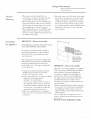
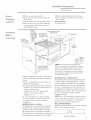
Electrical
Outlet16"Max.
FromLeft Side.
Install
2x4or 2x2
Anti-TipBlock ElectricalOutlet
AgainstRear FlushWith Side
CabinetWall ofCabinet7" Max.
9" FromFloor
to Bottom
of Block
ElectricalOutlet42"Max.
FromRightSide.
>/2 Install a Solid Barrier
-,z' Below a Cooktop
See Note
1-1/2" Cabinet Top
23-1/2"Min.
Solid Barrier
.Air Gap
Installa SolidBarrier
anda1/4" AirGap
AboveWarmingDrawer
• When installed, the fl'ont fi_ce of the drawer
will be nearly flush with a@_cent cabinetry
dooI'S.
• Drawer overlaps will conceal cut edges on
all sides of the opening,
The rough opening fin" the drawer must be:
- Depth: 23-1/2" rain. fl'om inside back to
front of cabinet fl'ame.
- Width: 25-1/2" fin" 27" wide models,
28-]/2" fin" 30" wide models.
- Height: 9-1/4".
• 5" rain. above floor or l" above toekick.
23-1/4" fi'om floor to bottom of cutout is
recollllllended t0i" tinder coHnterto l)
installation.
Installation below a cooktop:
Warming drawers are approved %r installa-
tion below only certain specified c{}{}kto I)
models, See the label attached to the top of
the warming drawer for api)roved models. A
solid barrier and air gap between cookto I) and
warming drawer is required, See Note above,
1"Min? 36"
Bountertop
9-1/4" ght
Dim. A
ZTDglO 28-1/2"
ZKDglO 25-1/2"
*NOTE: When installing thewarming drawer below a
cooktop,a solid barrier must beinstalled at least 1"from the
lowest point ofthe bottomof cooktop burner boxto the top of
cutout. Useany solid material suchas 1/4" thick plywood.
Allow at least 1/4" air gapbetween the barrier andthe top of
the warming drawer. See labelon top ofthe warming drawer
for approvedcooktopmodels.
Installation below a cabh_et drawer:
The warming drawer may be installed beneath
a cabinet drawer. In this installation, a solid
barrier should be installed above the warming
drawer to block access. Use any solid material
such as 1/4" thick i)lDvood. Allow at least 1/4"
air gap between the barrier and the top of the
warming drawer. Observe the 5" rain. above the
floor or ]" above the toekick minimum
installation height,
NOTE: If you are installing in fl'ameless cabinets,
it may be necessary to install 1/2" wide cleats to
accept drawer mounting scre_:s. See drawer to
find exact locations of mounting screws.
Side to Side Installation:
Install two warmii_g drawers in separate cutouts.
Allow 2" rain, between cutouts,
Side to Side Installation

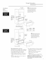
Design Information
War mi*_g"l)rawer
Installation
Below
Wall Ovens
NOTE:Additional clearance between
cutoutsmay be required. Checkto be
surethat ovensupports abovethe
Warming Drawer location does not
obstructthe requiredinterior 23-1/2"
depth and9-1/4" height.
2x2or 2x4
Anti-]ip Block
AgainstRear
Wall, 9" From
Floorto
Bottomof
Block
2" Min.
Overlapon
All Sides
2x2or2x4
Anti-TipBlock
Against
Wall, 9" From
Floorto
Bottomof
Block
1" Min.AboveToekickorAdjust
to OvenInstallationHeight
_-1/2' Min.
Inside_-
Oven
Cutout
Allow 5/8"
Overlap on
All Sides
/
NOTE:Additional clearance between
cutouts mayberequired. Checkto be
surethat oven supportsabovethe
Warming Drawer locationdoes not
obstruct the requiredinterior 23-1/2"
depth and9-1/4" height.
10-1/2"
1" Min.AboveToekick
When installed under a wall oven:
X,_arming ch'awers are approvecl for installation
below only certain specifiecl wall oven models.
See the label attached to the top of the
warming ch'awer for apl)roved models.
• When installe(1, the front lace of the drawer
will be nearly flush with a(!iacent cabinetry
cloors.
• Drawer overlaps will conceal cut edges on
all sides of the opening,
The rough opening fin" the drawer must be:
- Depth: 23-1/2" rain. fl'om insicle back to
fl'ont of cabinet fl'ame.
- Width: 25-1/9" fin" 27" wide models,
28-]/2" for 30" wide m oclels.
- Height: 9-1/4".
- Allow 2" rain. between oven ant1 drawer
cutouts for clearance of overlal)s.
NOTE: If you are installing in frameless cabinets, it may
be necessary to install 1/2" wide cleats to accept
drawer mounting screws. See drawer for mounting
screw locations.

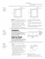
Installation
Warming" Drawer
P vide
Cabinet
Support
23-1/2"
2"x 4"or
EquivalentRunners
] / / _\
' J \=
=
= ,
=
=
=
=
=
=
=
=
=
=
=
=
=
=
=
=
,I
i
27"
IMPORTANT: When installed below asingle or doubleoven,
checkto besure that any ovensupports abovethe cutout do not
obstruct the 23-1/2" required depth of the warming drawer cutout.
• A 2" rain. clearance between ()veil and
wanning drawer cutouts are required.
Additional clearance may be required if
2 x 4 blocks are used to sui)port runners or
solid floor of the ()veil above.
• The warmer drawer may be supl)orted by
either a solid bottom, 2 x 4 or 2 x 2 runners.
23-1/F
I,
i
/.(j_ 2"x 4" or
Equivalent Runners
// _\ ,
/ \ :i
1
i
1
1
1
1
1
1
_2F_
30"
• The suI)I)ort must be level and rigidly
mounted, flush with the bottom edge of
the cutout.
- There is no way to level the drawer once
it has been installed. Be sure sui)ports are
level.
• The entire weight of the drawer is SUl)l)orted
by the itlnners or solid floor and mtlSt be
capable of supi)orting 150 lbs.
stq) z
Install
Anti-Tip
Brachets
WARNING:
ANTI-TIP PRECAUTIONS
An anti-tip brace must be installed to prevent
the drawer from tipping forward when
opened and loaded. Failure to do so could
result in personal injury.
PRI CAUTIONS :
CONTRE LE BASCULEMENT
Pour 6viter les blessures, il faut installer role
patte de retenue pour emp6cher le tiroir de
basculer quand il est ouvert et plein.
., 2x4 or 2x2 ...
/" Runners or Solid ".-
Bottom
Install
2x4or2x2
Anti-TipBlock
AgainstRear
CabinetWail
9" FrornFloor
to Bottorn
of Block
St@ 2
Install
Warming
Drawer
• Slide left corner of tile drawer into tile
opening.
• Push power cord into the hole leading to
the outlet location. Thread the cord through
as drawer is being i)ushed back into the
opening. Check to be sure power cord does
not get trapped tulcler tile drawer.
- If the outlet is installed inside the
opening, i)lug tile cord into tile outlet.
In this location, the excess power cord
length should be coiled and taped to
the right side of the unit.
• Push the drawer back tmtil the fl'ont flange
is flush to tile cabinet fl'ont.
• Open tile drawer flfllv.
• Drill pilot holes through tile holes in tile
overlaping fl'allle_ one on each Coi'nei',
• Drive wood screws provided into each coi'nei',
7

NOTE:While performing installations described in this book,
safety glasses or goggles should be worn.
Mon(g_a_ I( al_-_z e._)o a a, call
1.600.444. l,_4 5.
)
NOTE: 1 roduct improv( mere is a contim/ing (md(avor
at G(_n(_ral El(ctric. Tht r(for(_, materials, apF,(m_mlc(
and sl)ecificalions are sul_iect to change wilholll notic(.
Pub.No.49-8937-2
Dwg. No. 164D3333P167
09-04JR
PrintedintheUnitedStates
0
Monogram:
GEConsumer & Industrial
Louisvifle, KY40225
_2004 GE Company
-
 1
1
-
 2
2
-
 3
3
-
 4
4
-
 5
5
-
 6
6
-
 7
7
-
 8
8


GE ZKD910BF2BB Installation guide
- Category
- Warming drawers
- Type
- Installation guide
Ask a question and I''ll find the answer in the document
Finding information in a document is now easier with AI
Related papers
Other documents
-
 GE Monogram ZKD910 User manual
-
Sharp KB6100NK Installation guide
-
GE Monogram ZW9000SJSS Installation guide
-
-
Dacor EWD24 User manual
-
Monogram ZXD30B Installation guide
-
 GE Monogram ZXD27B Installation guide
-
 GE Monogram ZGU384N User manual
-
Jenn-Air JWD6030CDX Installation guide
-


