Page is loading ...

Smarter Thinking. Simpler Design.
Prosthetic Manual
TiLobe
®

Dear Customer,
Thank you for allowing Keystone Dental Inc. the opportunity to provide solutions which we
hope meet or exceed your expectations.
Keystone Dental Inc. produces innovative, high quality dental implants, accessories, and
biologics and distributes these products globally. Our headquarters are in Burlington,
Massachusetts and we have state-of-the-art manufacturing facilities in both Burlington and
Irvine, California.
Our range of implant products is broad, fulfilling both niche and standard requirements
for all specialties. If you wish, at any time, to discuss Keystone Dental products, ongoing
developments, and future research, or if you have any suggestions which you feel would
help us serve you better, please call me directly at (781) 328-3387 or Toll Free at (866)
902-9272.
Again, thank you for allowing Keystone Dental, Inc. to satisfy your implant requirements, and
I look forward to speaking with you in the future.
Michael A. Kehoe
Keystone Dental, Inc.
President & CEO

3
TABLE OF CONTENTS
Introduction
Design Features ............................................................................................................................................................. 4
Dimensions ..................................................................................................................................................................... 5
Treatment Planning ........................................................................................................................................................ 5
Healing Abutments ........................................................................................................................................................ 6
Consistent Contours ....................................................................................................................................................... 6
Torque Wrench Procedure .............................................................................................................................................. 7
Cleaning and Sterilization Procedure ........................................................................................................................... 7
Restorative Options
Cement-Retained Restorations ...................................................................................................................................... 8
Screw-Retained Restorations ......................................................................................................................................... 8
Implant Overdenture Restorations ................................................................................................................................ 9
Implant- or Bar-Retained Overdenture Restorations ................................................................................................... 9
Impression Techniques
Open Tray (Direct) Impression Post Technique ........................................................................................................... 12
Closed Tray (Indirect) Impression Post Technique ...................................................................................................... 12
Laboratory Cast Fabrication .......................................................................................................................................... 13
Temporization Procedures
Screw-Retained Temporization – Chairside ................................................................................................................. 14
Cement-Retained Restorations
Esthetic Contour Ti Abutment ...................................................................................................................................... 16
a. Lab Preparation of the Esthetic Contour Ti Abutment .................................................................................... 17
b. Chairside Preparation of the Esthetic Contour Ti Abutment ............................................................................ 20
UCLA Gold/Plastic Sleeve – Custom Abutment .......................................................................................................... 23
Quick-Abutment System ................................................................................................................................................ 27
Screw-Retained Restorations
UCLA Abutment System ................................................................................................................................................ 34
LOCATOR
®
Abutment System
How to use the LOCATOR
®
Tool .................................................................................................................................... 39
Chairside Placement of the LOCATOR
®
Abutment – New Denture ........................................................................... 40
Chairside Placement of the LOCATOR
®
Abutment – Existing Denture ...................................................................... 42
Reline and Rebase a LOCATOR
®
Case ......................................................................................................................... 44
LOCATOR R-Tx
TM
Abutment System.......................................................................................................45

4
Introduction
This manual serves as a reference to aid clinicians and dental technicians
in restorative procedures for Keystone Dental’s TiLobe
®
connection
implants and prosthetic components. It is not intended to describe the
methods or procedures for diagnosis, treatment planning, placement
or restoration; nor does it replace clinical training or clinical judgment
regarding the needs of each patient.
Keystone Dental recommends appropriate training as a prerequisite
for the placement/restoration of implants and associated treatment.
The procedures described within this manual reflect idealized patient
presentations with conditions adequate for commencement of the
restorative phase of treatment. No attempt has been made to cover
the wide range of actual patient conditions which may adversely affect
prosthetic outcomes.
Design Features
TiLobe
®
connection implant systems share three diameter prosthetic
platforms with a secure, patented internal 6-lobed connection to
allow complete cross-compatibility between the systems. The TiLobe
®
connection utilizes the same screw diameter throughout all implant
diameters.
Introduction & Characteristics
8.5˚ Taper
6-Lobe Connection
Pilot

5
Dimensions
TiLobe
®
implants are available in a variety of platform diameters and
lengths. The label icons below identify the prosthetic components that
will mate with each platform diameter and represent the diameter
compatibility of the prosthetic connections of the TiLobe
®
implant
systems.
Identifies all 4.0 and 5.0 flare prosthetic components that
will mate with the Ø3.5 mm and Ø3.8 mm implants.
Ø3.5 mm and Ø3.8 mm implants are available in lengths of
8.5 - 16 mm.
Identifies all 5.0 and 6.0 flare prosthetic components that
will mate with the Ø4.1 mm and Ø4.5 mm implants.
Ø4.1 mm and Ø4.5 mm implants are available in lengths of
8 - 16 mm.
Identifies all 5.0, 6.0 & 7.0 flare prosthetic components that
will mate with the Ø5.0 mm and Ø5.5 mm implants.
Ø5.0 mm and Ø5.5 mm implants are available in lengths of
8.5 - 15 mm.
Identifies all 7.0 & 8.0 flare prosthetic components that will
mate with the Ø6.5 mm implants.
Ø6.5 mm implants are available in lengths of 8.5 - 13 mm.
Identifies all 7.0 flare prosthetic components that will mate
with the Ø7.0 mm implants.
Ø7.0 mm implants are available in lengths of 7.0, 9.0 &
11.0 mm.
Identifies all 8.0 & 9.0 flare prosthetic components that will
mate with the Ø8.0 mm implants.
Ø8.0 mm implants are available in lengths of 7.0, 9.0 &
11.0 mm.
Identifies all 8.0 & 9.0 flare prosthetic components that will
mate with the Ø9.0 mm implants.
Ø9.0 mm implants are available in lengths of 7.0, 9.0 &
11.0 mm.
* For specifics on implant lengths please refer to the Keystone Dental Product Catalogs.
All products may not be available in all markets.
Treatment Planning
Successful treatment requires the coordinated efforts of the implanting
surgeon, the restorative dentist, and the dental technician. A pre-
surgical treatment option discussion between these individuals helps to
determine the appropriate restorative strategy and adds balance between
the surgical objectives and esthetics, phonetics, and function of the final
prosthesis. In addition, this coordinated approach ensures that treatment
is complete, there is no omission of important technical considerations,
such as the use of a surgical guide for implant positioning, and that the
biomechanics of the final prosthesis are maintained.
DIAGNOSTIC CASTS
Mounted study casts and a diagnostic wax-up are the foundation for
determining implant location. The implanting surgeon, the restoring
dentist, and the dental technician should work together to produce
diagnostic wax-ups and a surgical guide.
SURGICAL GUIDES
A surgical guide is used to indicate practical boundaries for the placement
of implants and may prevent them from being placed too buccal/
lingually or mesial/distally. This process helps to ensure functional
placement of implants and esthetic results. The implanting surgeon
should communicate to the dental technician any conditions that may
affect guide design (e.g., the type of incision that will be used, expected
reflection of tissue, etc.) The designed surgical guide also provides
information relating to ideal tooth shape and supporting bone structures
that may have been lost.
Introduction & Characteristics
3.5
3.8
5.0
4.1
3.5
3.5
3.8
5.0
4.1
3.5
3.5
3.8
5.0
4.1
3.5
3.5
3.8
5.0
4.1
3.5
3.5
3.8
5.0
4.1
3.5
3.5
3.8
5.0
4.1
3.5
3.5
3.8
5.0
4.1
3.5
3.5
3.8
3.5
3.8
3.5
3.8

6
Healing Abutments
The healing abutment is a one-piece component, designed to support optimal esthetic results. This abutment is used for soft tissue contouring during the
healing phase and can be used for both one- and two-stage surgeries.
Intended Applications
• For all positions in the mouth
• For intermediate use only
Recommended Torque – 10 Ncm
The healing abutment is laser etched with numbers to identify implant diameter, contour and height of the healing abutment.
Consistent Contours
Keystone Dental TiLobe
®
prosthetics offer a complete line of restorative products with consistent contours from healing abutments, temporary abutments,
and impression copings to the final abutments for each prosthetic platform. If the surgeon has placed a specific flared healing abutment, it is important to
use components with the same emergence profile throughout the treatment plan. This will ensure easy seating of prosthetic components and support of the
soft tissue contours, without causing discomfort for the patient by blanching of the soft tissue.
The chart below defines the available contours for each prosthetic platform.
Introduction & Characteristics
4.5Ø
identifies the diameter
of the implant
3
identifies the height
of the healing abutment
5.0
identifies the flare
of the healing abutment
Implant Diameter Available Flares
Ø3.5, Ø3.8 4.0, 5.0 mm
Ø4.1, Ø4.5 5.0, 6.0 mm
Ø5.0, Ø5.5 5.0, 6.0, 7.0 mm
Ø6.5 7.0, 8.0 mm
Ø7.0 7.0 mm
Ø8.0 8.0, 9.0 mm
Ø9.0 8.0, 9.0 mm
Healing
Abutment
Temporary
Abutment
Contoured
Implant
Impression Post
Esthetic
Contour Ti
Abutment
Quick-Abutment

7
Torque Wrench Procedure
The measurement of torque is extremely important in the success of restorative procedures. All TiLobe
®
final
abutment screws have a recommended torque of 30 Ncm. To assure proper torque is applied, set the wrench to the
desired value by turning the torque meter dial until the desired torque value is shown in the window on the handle
of the torque wrench. Align the marking on the torque meter dial with the markings on either side of the window.
To apply torque to the abutment screw, turn the wrench slowly in a clockwise direction.
NOTE: The word “IN” should appear on the top of the wrench when turning in a clockwise direction.
Continue turning until the wrench “slips.” When the wrench slips a clicking sound is heard and tension is released
on the torque wrench. This indicates that the pre-set torque value has been reached and assures that the proper
torque value has been delivered.
For additional information and cleaning/sterilization instructions, please refer to the Surgical Ratchet/Torque
Wrench Instructions For Use.
NOTE: It is recommended to torque the TiLobe
®
final abutment screw twice. First torque the abutment screw to the
recommended 30 Ncm. Allow 10 minutes for screw relaxation and then torque again to the recommended 30 Ncm.
Cleaning and Sterilization Procedure
Certain prosthetic components are provided in sterile, gamma irradiated packaging. Please refer to individual package labeling to determine if the prosthetic
component is sterile. Before installation, non-sterile abutments must undergo a cleaning and sterilization procedure. This procedure should preferably take
place in an ultrasonic unit with a mixture of dishwashing detergent and water. For sterilization procedures, follow the instructions below:
Abutment Sterilization Procedure
Ti Temporary Abutment
UCLA Gold/Plastic Abutment*
Steam Sterilization Gravity Cycle:
134°C (~ 273°F) 20 minute exposure / 40 minute dry time
Steam Sterilization Pre Vacuum Cycle:
134°C (~273°F) 4 minute exposure / 40 minute dry time
Healing Abutment
Impression Posts
PMMA Temporary Abutment
Esthetic Contour Ti Abutment
Quick-Abutment
Final Abutment Screw
LOCATOR
®
Abutment
Not required. Sterile when delivered.
CAUTION: Do not steam autoclave plastic parts.
*It is recommended that the finished custom UCLA abutment from the dental laboratory be sterilized according to sterilization procedures listed above for the
UCLA Gold/Plastic Abutment.
Introduction & Characteristics

8
Restorative Options
Cement-Retained Restorations
Cement-retained implant restorations are very similar to traditional crown and bridge restorations. An abutment is prepared and is screwed onto the
implant. The screw access hole is protected for retrieval of the abutment, if necessary. The restoration is cemented to the prepared abutment.
a. Intended Applications
• Single or multiple-unit implant restorations.
• Fully or partially edentulous arch.
• All tooth positions.
b. Advantages
• Use of conventional crown and bridge techniques.
• Maintaining of optimum occlusal integrity by the intact occlusal surface of the cement-retained restoration.
• Flexibility to achieve optimal esthetics.
c. Disadvantages
• Difficulty in retrieving the restoration, if necessary.
Screw-Retained Restorations
Screw-retained restorations are indicated when inter-arch space is limited and/or a screw-retained restoration is planned. In this application, the abutment
and restoration are all one piece, seated on the implant, and retained by a screw that enters through the occlusal surface of the prosthesis.
a. Intended Applications
• Single or multiple-unit implant restorations.
• Fixed-detachable (hybrid-type) restorations.
• Fully or partially edentulous arch.
• All tooth positions.
b. Advantages
• Ease of retrievability for hygiene maintenance.
• Minimal inter-arch space is required.
c. Disadvantages
• Splinted restorations on implants with divergent angles greater than 10°.
• Screw holes for wider implants may be highly unesthetic.
Restorative Options

9
Restorative Options
Implant Overdenture Restoration - Attachment-Retained
The denture is retained in the mouth with an attachment mechanism supported by tissue. It contains a metal housing and a retentive insert to secure the
denture to the implant abutments. The abutments screw directly into the implant, providing a choice of retention options.
a. Intended Applications
• Maladaptive or dissatisfied denture patients requiring greater retention and oral comfort.
• Patients who desire a more stable mandibular denture.
• Partially edentulous patients with severely compromised dentition (i.e., about to become edentulous) that
cannot be successfully maintained to retain or support a prosthesis.
• Ideally Canine or Lateral Position to reduce tendency for denture to rotate around the fulcrum.
b. Advantages
• Prosthesis is removable for easier oral hygiene access.
• Existing denture may be used.
• Low financial investment by the patient.
c. Disadvantages
• None when contraindications are not present.
d. Number of implants
• In the mandible, two to four implants are recommended for an Implant Overdenture Restoration - Stud Type.
• In the maxilla, a minimum of four implants are recommended for an Implant Overdenture Restoration - Stud Type.
Implant- or Bar-Retained Overdenture Restorations
Screw-retained restorations are also used for bar-supported and/or implant-supported overdenture cases. The denture is retained by the bar with
attachments, i.e. clips or ball attachments or fixed directly to the bar and screwed to the implants (Fixed-detachable or Hybrid types).
NOTE: An implant-retained, tissue-supported prosthesis is indicated when there are fewer than four implants in the mandible and fewer than six in the maxilla.
a. Intended Applications
• Multiple-unit restorations.
• Areas where extensive bone loss has occurred.
• Excessive inter-occlusal space.
• Fully edentulous patients in the maxillae or mandible.
Restorative Options

10
b. Advantages
• Bar-supported overdenture:
– Easily removed by patient.
– Easier hygiene maintenance by patient.
• Implant-supported overdenture:
– Fixed (not removable).
c. Disadvantages
• Inter-occlusal space between the maxilla and mandible is limited.
d. Number of implants
• In the mandible, four to six implants are recommended for an implant-supported/implant-retained prosthesis.
• In the maxilla, six to ten implants are recommended for an implant-supported/implant-retained prosthesis.
Restorative Options

11
Impression Techniques
There are three (3) types of impression techniques utilized in implant dentistry:
Prepared Abutment – An abutment is placed and prepared in the mouth using copious amounts of irrigation. The abutment screw is tightened to the
recommended torque. An impression is taken with the prepared abutment in place.
Implant-level – The healing abutment is removed and an impression post is placed on the implant. An impression is taken to transfer the lobe position,
angle, contour of the tissue and depth of the implant.
Abutment-level – The healing abutment is removed and an unprepared abutment is seated on the implant in the patient’s mouth. An impression post or
impression cap is placed onto the abutment. The abutment and abutment screw position are recorded for screw- or cement-retained prosthesis.
Implant-level and Abutment-level impressions can be made by either of the following techniques:
• Open Tray (Direct) Pick-up Impression Technique
• Closed Tray (Indirect) Impression Technique
The option chosen is dependent on the treatment plan and the degree of accuracy needed to fabricate the final restoration. The open tray technique is
considered more accurate than the closed tray technique and is recommended in multiple-unit restorations. Impression posts for the TiLobe
®
connection are
packaged with a short and long screw for use in either open or closed tray impressions.
To select the proper platform diameter open or closed tray impression post(s), match the color of the post to the implant diameter located on the label.
Selection of the proper contour should be consistent with the contour of the healing abutment.
Open Tray (Direct) Pick Up Impression Post
This technique requires use of an impression post body and a long screw. The open tray impression post
transfers the position of the internal 6-lobes, angle of the implant, contours of the tissue and depth of
the implant in the osteotomy. Open tray impression posts are recommended for use when an impression
is made of multiple divergent implants.
Closed Tray (Indirect) Impression Post
This technique requires use of an impression post body and a short screw. The closed tray impression
post transfers the position of the internal 6-lobes, angle of the implant, contours of the tissue and depth
of the implant in the osteotomy. Closed tray impression posts are ideal for use in limited inter-arch
space.
Impression
Post Body
Impression
Post Body
Long
Screw
Long
Screw
Impression Techniques
Impression
Post Body
Impression
Post Body
Short
Screw
Short
Screw

12
Procedure For Open Tray (Direct) Pick Up Impression Post Technique
(Example shown is a 4.1/4.5 mm TiLobe
®
connection implant with a 5.0 mm flare healing abutment)
Step 1
The 5.0 mm flare healing abutment is removed with the quad driver.
Step 2
The impression post is positioned into the internal TiLobe
®
of the implant and fully seated with the quad driver.
NOTE: Take a radiograph to verify the proper fit between the impression post and the implant.
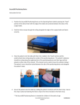
Step 3
It is recommended to locate the screw head to facilitate access after the impression and prevent impression
material from obstructing the screw head. A light or medium body impression material is injected around the
implant/impression post junction at the gingival aspect. Then the customized impression tray is completely filled
with heavy body or putty impression material and fully seated to take the impression.
Step 4
Once the impression material has set, the screw of the impression post is loosened and the impression with the
impression post is removed. The analog is then attached to the impression post and the impression post/analog
assembly, with the retention screw is sent to the laboratory, including an impression of the opposing arch and a
proper jaw relation record. The healing abutment is placed onto the implant or a temporary crown is seated.
Step 5
Once the dental stone has fully set, remove the long screw and the impression post tray from the cast. At this time,
abutment choices are finalized and the restoration fabricated.
For a chairside fabricated temporary crown, place the Temporary (PMMA) or Ti (Titanium) Temporary Abutment
using the quad driver and shorten to the appropriate occlusal scheme. The Final Abutment Screw is torqued at
20 Ncm onto the implant. Then the crown, fabricated chairside or previously provided by the laboratory, is placed.
Procedure For Closed Tray (Indirect) Pick Up Impression Post Technique
(Example shown is a 4.1/4.5 mm TiLobe
®
connection implant with a 5.0 mm flare healing abutment)
Step 1
The 5.0 mm flare healing abutment is removed with the quad driver.
Step 2
The impression post is positioned into the internal TiLobe
®
of the implant and fully seated with the quad driver.
Impression Techniques

13
NOTE: Take a radiograph to verify the proper fit between the impression post and the implant.
Step 3
A light or medium body impression material is injected around the implant/impression post junction at the gingival
aspect. Then the customized impression tray is completely filled with heavy body or putty impression material and
fully seated to take the impression.
Step 4
Once the impression material is completely set, the impression tray can be removed leaving the impression post
still attached to the implant. The impression post can now be removed and transferred back into the impression.
The impression post must be completely seated with the correct orientation, preferably under magnification. The
impression with the impression post/analog assembly and screw is sent to the laboratory, including an impression
of the opposing arch and a proper jaw relation record. The healing abutment is placed onto the implant or a
temporary crown is seated.
Step 5
Once the dental stone has fully set, remove the impression tray and the posts from the cast. At this time, abutment
choices are finalized and the restoration is fabricated.
For a chairside fabricated temporary crown, place the Temporary (PMMA) or Ti (Titanium) Temporary Abutment
using the quad driver and shorten to the appropriate occlusal scheme. The Final Abutment Screw is torqued at
20 Ncm onto the implant. Then the crown, fabricated chairside or previously provided by the laboratory, is placed.
Laboratory Cast Fabrication – Dental Laboratory
Step 1
Once the impression, bite, opposing model, shade and instructions have been received by the dental laboratory,
inspect the impression for accuracy.
Step 2
Please refer to IMPRESSION TECHNIQUES, Open Tray (Direct) Technique or Closed Tray (Indirect) Technique for
attaching of implant analog if the clinician did not attach the analog prior to sending the case to the laboratory.
Step 3
A soft tissue model is recommended to be made around the implant site.
Step 4
Pour a working cast in minimal expansion, high hardness die stone. Articulate according to normal laboratory
procedures.
Impression Techniques

14
Temporization Procedures
The TiLobe
®
connection offers 2 types of temporary abutments for temporization. The first option is a Temporary
Abutment of an acrylic PMMA (polymethylmethacrylate) with a metal substructure. This abutment is fabricated
from an esthetic tooth-colored polymer which is easily modified and bonds well with common temporary
materials including acrylic and composite. The second option is a Ti (Titanium) Temporary Abutment. With
this abutment, the acrylic is mechanically bonded to the metal substructure. Both temporization options are
available in locking and non-locking designs.
Intended Applications
• Cement- and screw-retained restorations.
• Single or multiple units, partial and full edentulous restorations.
• All tooth positions.
The use of temporary restorations is dependent on the treatment plan, the requirements of the patient and the
final restoration planned.
Screw-Retained Temporization – Chairside
Step 1
Using the master cast, place a denture tooth in the edentulous area and then fabricate a vacuum-formed stent
using 0.02 stent material.
Step 2
Place the Temporary (PMMA) or Ti (Titanium) Temporary Abutment using the quad driver and the laboratory
screw.
Step 3
Prepare the abutment as necessary so there is adequate space for acrylic between the stent and the abutment.
Step 4
Block-out the abutment screw access hole to prevent acrylic from flowing inside.
Step 5
Place the temporary acrylic material of choice into the stent and place the stent over the adjacent teeth. (Follow
manufacturer’s recommendations for curing times.)
Temporary
Abutment
Ti Temporary
Abutment
Temporization Procedures

15
Step 6
Remove the stent and separate it from the acrylic temporary abutment.
Step 7
Remove the temporary restoration using the quad driver and adjust the acrylic for optimum emergence and contour
through the tissue, while keeping the bite out of occlusion.
Step 8
Proceed with the final insertion using the Quad Driver Torque Tip and Torque Wrench and tighten the screw to 20
Ncm.
Step 9
Included with the temporary abutment is an occlusal plug for protection of the screw. Modify the occlusal plug and
seat into the screw access hole. Cover the remaining portion of the screw access hole with composite.
Temporization Procedures

16
Esthetic Contour Ti Abutment
The Esthetic Contour Ti Abutment is a pre-machined abutment with anatomical margins that are designed to follow gingival contours. The abutment is held
in place in the implant using a final screw that is included with the abutment. The abutment is anodized and follows traditional prosthodontic cement-
retained procedures.
Intended Applications
• Single, partial and fully edentulous restorations.
• All tooth positions.
Configurations
• Straight and 15˚ Angled designs.
• Cuff heights of 0.5 mm, 1.0 mm, 1.5 mm, and 3.0 mm.
Technical Considerations
• A minimum inter-occlusal distance of 4.5 mm plus the restoration thickness is required between the implant prosthetic table and the occlusal plane.
• It is recommended that the Abutment Lab Screw be used during laboratory procedures to avoid damage to the Final Abutment Screw.
• Torque Recommendations – 30 Ncm.
Esthetic Contour Ti Abutments and tools needed:
There are two methods for preparation of cement-retained Esthetic Contour Ti Abutments:
a. An implant level impression is taken; the dental technician prepares the abutment, and sends the abutment and final restoration back to the
clinician. See the following section on LAB PREPARATION OF THE ESTHETIC CONTOUR TI ABUTMENT.
b. Chairside preparation of a cement-retained abutment, see section CHAIRSIDE PREPARATION AND TEMPORIZATION BY THE CLINICIAN.
Cement-Retained Restorations
Quad Driver
Swivel Head
Quad Driver
Torque Tip
Torque Wrench
Final Abutment
Screw
Laboratory
Screw
Esthetic Contour Ti Abutment
(Straight or 15˚ Angle)

17
a. LAB PREPARATION OF THE ESTHETIC CONTOUR TI ABUTMENT
LABORATORY SECTION
Laboratory Cast Fabrication
Step 1
Pour the soft tissue around the implant analog. When the material has set, pour a stone laboratory cast.
Esthetic Contour Ti Straight or 15˚ Angled Abutment Selection and Modification
Step 2
When selecting the proper Esthetic Contour Ti Abutment cuff height, measure the tissue depth from the top of the
implant analog to the height of the soft tissue.
NOTE: For esthetics, the final margin of the Esthetic Straight or 15˚ Angled Abutment should be 1 - 2 mm below
tissue height.
Step 3
Place the Esthetic Contour Ti Abutment using the laboratory screw and the quad driver. Determine if reduction in
the height of the abutment and/or the cuff is required. Mark the abutment for the required vertical reduction and
gingival contour.
Step 4
Modify the Esthetic Contour Ti Abutment.
NOTE: To improve stability when adjusting the Esthetic Contour Ti Abutment, attach an implant analog to the abutment.
NOTE: For single unit cases, it is recommended to mark the buccal of the abutment with a bur mark to assist the
clinician with orientation in the mouth.
NOTE: The laboratory may fabricate a “positioning jig” using a pattern resin material. Using the positioning jig,
the clinician can transfer the abutment from the master model to the mouth, simplifying the abutment seating
procedure.
Step 5
After preparation is complete, block out the top of the screw access hole to prevent wax from flowing into the area.
Cement-Retained Restorations

18
Metal Coping/Framework Fabrication
Step 6
Construct and wax the coping/metal framework following conventional crown and bridge procedures.
Step 7
Sprue, invest and cast following conventional crown and bridge techniques.
Step 8
Divest and finish the coping/metal framework using conventional crown and bridge techniques.
NOTE: If a multi-unit restoration was requested by the clinician to confirm a passive fit of multi-unit restorations,
an intra-oral metal try-in is recommended.
Step 9
If there is no metal framework fitting assessment, proceed to section Porcelain Application and follow standard
laboratory procedures.
CLINICAL SECTION
Metal Framework Fitting Assessment
Step 1
Remove the metal framework from the master model. Before placement in the mouth, note the orientation
marks on the model and on the Esthetic Contour Ti Abutments placed by the dental technician.
Step 2
Place the Esthetic Contour Ti Abutments in the patient’s mouth. Verify that the position of the orientation mark
is towards the buccal.
Step 3
Use the quad driver and the lab abutment screw to hand tighten the abutments.
Step 4
Take a radiograph to verify that the abutments are completely seated.
Cement-Retained Restorations

19
Step 5
Seat the coping/metal framework and verify that the framework fits passively and completely over the Esthetic
Contour Ti Abutments.
NOTE: If the framework binds as it is seated or does not go completely down to the margin of the abutments, then
the bridge must be cut, orientated in the mouth, and returned to the laboratory for soldering/laser welding. It may
be possible to use an indicating spray or paste to determine if the internal aspect of the bridge can be modified to
allow the bridge to seat.
Step 6
Reseat the sections in the mouth and lute the sections of the framework together using a pattern resin material.
Once the material has set (according to the manufacturer’s specifications):
• Return the metal framework to the laboratory to be soldered/laser welded and returned for a second
framework fit assessment.
OR
• Pick up the luted together framework in a secondary full arch impression. Return the impression to the
laboratory for soldering/laser welding and porcelain application.
Step 7
If the metal framework did fit passively and completely, it can be removed along with the Esthetic Contour Ti
Abutments and returned to the laboratory.
LABORATORY SECTION
Porcelain Application
Proceed with porcelain application following standard laboratory procedures.
CLINICAL SECTION
Final Insertion
Step 1
After the healing abutment or temporary crown is removed, the Esthetic Contour Ti Abutment is seated onto the
implant by engaging the Final Abutment Screw with a quad driver. Then a radiograph is taken to ensure proper
seating of the abutment. At this point, the quad driver Torque Tip is inserted into the Torque Wrench and the Final
Abutment Screw is tightened to 30 Ncm. After 10 minutes, a secondary torque of 30 Ncm must be applied.
Take a radiograph to verify the abutment is seated completely.
Cement-Retained Restorations

20
Step 2
The crown is placed and occlusion and esthetics are evaluated and adjusted as necessary.
NOTE: It is recommended that the screw access hole be blocked out to protect the screw. At this point, the
crown is cemented onto the Esthetic Contour Ti Abutment. All excess cement must be meticulously removed
and the occlusion evaluated once more. The patient is then provided with oral hygiene instructions and a recall
appointment is recommended.
b. CHAIRSIDE PREPARATION AND TEMPORIZATION BY THE CLINICIAN
CLINICAL SECTION
Chairside Preparation
NOTE: When intraoral abutment modification is necessary, use copious amounts of irrigation to eliminate excessive
heat buildup in the surrounding bone tissue that may compromise the osseointegration of the implant
Step 1
When selecting the proper Esthetic Contour Ti Abutment cuff height, measure the tissue depth from the top of
the implant to the height of the soft tissue.
NOTE: For esthetics, the final margin of the Esthetic Contour Straight or 15˚ Angled Abutment should be 1 - 2
mm below tissue height.
Step 2
Place the Esthetic Contour Ti Abutment using the laboratory screw and the quad driver. Determine if reduction in the
height of the abutment and/or the cuff is required. Mark the abutment for the required vertical reduction and gingival
contour.
Step 3
Remove and modify the abutment using carbide burs, cut-off disks or heatless stone wheels. A diamond bur
may be used to define the margins. Create a mark to indicate the buccal surface to assist in orientation of the
abutment in the mouth. If the flat of the abutment is removed during the preparation, a new anti-rotational
feature must be defined on the abutment.
TIP: To improve abutment stability while adjusting the fit, attach an implant analog to the abutment.
Cement-Retained Restorations
/