Reznor RCA Installation guide

Category
Heat pumps
Type
Installation guide

This manual is also suitable for

Form I-MAPS II, P/N 206131 (Rev 13), Page 1
MAPS
®
II
Model RDCA
Form I-MAPS II (Version B)
Obsoletes Form I-MAPS II (Version A)
Installation/Operation
Applies to: MAPS II Model Series RCA, RDA,
RDCA, RDDA, RECA, REDA, and JHUP
Modular Air Processing Systems
FOR YOUR SAFETY
If you smell gas:
• Open windows.
• Do not touch any electrical switches.
• Extinguish any open ame.
• Immediately call your gas supplier.
FOR YOUR SAFETY
The use and storage of gasoline or other ammable vapors and liquids in open
containers in the vicinity of this appliance is hazardous.
WARNING:
All MAPS
®
II modular air processing systems contain either chlorodiuoromethane
(HCFC-22) or a hydro-uorocarbon blend (HFC-407C). HCFC-22 is believed
to harm the public health and environment by destroying ozone in the
upper atmosphere. Do not release HCFC-22 to the atmosphere. The
U. S. Clean Air Act requires the recovery of any residual refrigerant.
WARNING:
Improper installation, adjustment, alteration, service, or maintenance can cause
property damage, injury, or death. Read the installation, operation, and maintenance
instructions thoroughly before installing or servicing this equipment.
®
A
G
E
N
C
Y
P
R
O
C
E
S
S
S
T
A
R
T
-
U
P
P
R
O
D
U
C
T
C
U
S
T
O
M
E
R
W
A
R
R
A
N
T
Y
C
O
N
V
E
R
G
E
N
T
Q
U
A
L
I
T
Y
S
Y
S
T
E
M
CQS
CQS
®
Form I-MAPS II, Page 2
1.1 Cautions and Warnings
There are warning labels on the unit, on the front page, and throughout this
manual. For your safety, comply with all warnings during installation, opera-
tion, and service of this system. Denitions of the hazard intensity levels of the
cautions, warnings, and dangers are shown below.
1. General
HAZARD INTENSITY LEVELS
1. DANGER: Failure to comply will result in severe personal
injury or death and/or property damage.
2. WARNING: Failure to comply could result in severe personal
injury or death and/or property damage.
3. CAUTION: Failure to comply could result in minor personal
injury and/or property damage.
Denitions of Hazard
Intensity Levels used
in this Manual
1. General ..........................................................2
1.1 Cautions and Warnings .................................... 2
1.2 General Information ......................................... 3
1.3 Warranty ........................................................... 4
1.4 Installation Codes ............................................. 4
2. Location .........................................................4
3. Receiving, Moving, and Storage .................5
3.1 Receiving and Moving ...................................... 5
3.2 Storage and Installation Checks ...................... 6
4. Dimensions and Clearances ........................7
4.1 Dimensions - RCA, RDA, RDCA, RDDA .......... 7
4.2 Dimensions - RECA, REDA ............................. 8
4.3 Clearances ...................................................... 9
5. Mounting ........................................................9
5.1 Approximate Weights ....................................... 9
5.2 Roof Curb ....................................................... 12
5.3 Curb Heater Section, Model JHUP-0250 ....... 17
5.4 Rigging and Lifting ........................................ 17
6. Mechanical ..................................................18
6.1 Duct Connections ........................................... 18
6.2 Condensate Drain ......................................... 19
6.3 Inlet Air Hood .................................................. 20
6.4 Blowers, Belts, and Drives ............................. 22
7. Electrical and Wiring ..................................24
7.1 General, Wiring Diagram, and Unit
Wiring Requirements ....................................... 24
7.2 Supply Wiring ................................................ 24
7.3 Disconnect Switch .......................................... 25
7.4 Control Wiring ............................................... 25
7.5 Blower Motor .................................................. 26
7.6 Condenser Fan Motors and Fans .................. 26
7.7 Compressors .................................................. 26
8. Controls .......................................................28
8.1 Digital Control Systems ................................. 28
8.2 Remote Console ............................................ 31
8.3 Control Locations .......................................... 32
8.4 Miscellaneous Electrical / Control Options ..... 33
9. Optional Equipment including
Heat Sections ..............................................34
9.1 Inlet Air Control and Energy Recovery
Options ........................................................... 34
9.2 Power Exhaust (Building) ............................... 38
9.3 Gas Heat Module - Models RDCA & RDDA ... 39
9.4 Curb Section with Gas-Fired Duct Furnace,
Model JHUP-0250 .......................................... 50
9.5 Electric Heat Section - Model RECA and
Model REDA .................................................. 51
10. Commissioning and Startup ...................52
10.1 General ........................................................ 52
10.2 Checklist Prior to Startup ............................ 52
10.3 Checklist - Startup ....................................... 53
10.4 Checklist After Startup: ................................. 56
10.5 Startup Form ................................................ 57
APPENDIX .......................................................58
Cross-Reference by Model/Size and Cabinet
Size A, B, or C .................................................. 58
Technical Data ..................................................... 59
Wiring Diagram Option Identication .................... 60
Pressure/Temperature Chart for Checking
Superheat and Subcooling ............................... 61
Index ................................................................62
References .....................................................63
Table of Contents
Form I-MAPS II, P/N 206131 (Rev 13), Page 3
Model Description
RCA
Makeup Air Cooling Packaged System, 800-10000 CFM
RDCA
Makeup Air Cooling Packaged System, 800-10000 CFM, with Gas
Heat Section (100-700 MBH)
RECA
Makeup Air Cooling Packaged System, 800-10000 CFM, with
Electric Heat Section (5-88 kw)
RDA
Makeup Air Cooling and Dehumidication Reheat Cycle Packaged
System, 800-10000 CFM
RDDA
Makeup Air Cooling and Dehumidication Reheat Cycle Packaged
System, 800-10000 CFM, with a Gas Heat Section (100-700 MBH)
REDA
Makeup Air Cooling and Dehumidication Reheat Cycle Packaged
System, 800-10000 CFM, with an Electric Heat Section (5-88 kw)
JHUP
Supplemental Gas-Fired Duct Furnace
WARNING:
Gas-red appliances are not designed for use in hazardous
atmospheres containing ammable vapors or combustible
dust, in atmospheres containing chlorinated or halogenated
hydrocarbons, or in applications with airborne silicone
substances. See Hazard Levels, above.
WARNING:
Should overheating occur, or the gas supply fail to shut
off, shut off the manual gas valve to the appliance before
shutting off the electrical supply.
WARNING:
Do not use this appliance if any part has been under water.
Immediately call a qualied service technician to inspect
the appliance and replace any gas control that has been
under water.
Warnings for Models
RCDA and RDDA with
Gas Heat Section
1.2 General
Information
Read this booklet and become familiar with the installation requirements of your
particular model. If you do not have knowledge of local requirements, check
with the local agencies who might have requirements concerning this installa-
tion. Before beginning, make preparations for necessary supplies, tools, and
manpower.
Some information is by cabinet size; see cross-reference table in the APPEN-
DIX, page 58.
This booklet includes installation and operation information. Before beginning
any procedure, carefully review the information, paying particular attention to
the warnings. Handling of refrigerant should only be performed by a certied
HVAC technician in compliance with all codes and requirements of authorities
having jurisdiction.
The instructions in this manual apply to the following MAPS
®
II models:
Form I-MAPS II, Page 4
1.3 Warranty
Refer to limited warranty information on the warranty form in the "Literature
Bag" shipped with this system. If an optional extended warranty applies, keep
the extended warranty information for future reference and verication of war-
ranty.
Massachusetts
Requirements
If being installed in the Commonwealth of Massachusetts, this unit must be
installed by a licensed plumber or licensed gas tter.
California Warning
Label
If a gas-red heat section is included and the system is being installed in the
state of California, the installer MUST attach a warning label on the outside of
the heat section access panel. The California Warning label is shipped in the
"Literature Bag". If installation is in California, select a dry, clean location on the
heat section access panel and adhere the label.
3. Receiving,
Moving, and
Storage
1. General (cont'd)
1.4 Installation Codes
These packaged systems are certied by ITS to Heating Cooling Equipment
(latest edition), UL 1995 / CAN/CSA C22.2 No. 236. Electrical characteristics
are shown on the system rating plate. All cooling and dehumidication reheat
cycle circuits are factory-charged with R-22 or R407C refrigerant.
Model RDCA and Model RDDA include a gas heat section. The system
includes a power-vented gas-fueled duct furnace. The gas-red furnace using
the Reznor
®
TCORE
combustion system is available in 13 sizes from 100 to
700 MBH for use with either natural or propane gas. The furnace is certied by
ITS to both ANSI Z83.8b and CSA 2.6b-M. The ETL label, type of gas, and the
ring rate are shown on the heat section rating plate.
Model RECA and Model REDA include an electric heat section. The electric
heat section is available in 21 sizes from 5 to 88 kw with single or three-stage
control. Refer to the system rating plate for electrical requirements. Models
RECA and REDA require only a single-point electrical supply.
Approval and
Installation Codes
2. Location
All of these packaged systems are designed to be mounted on a roof or slab
using a manufacturer designed curb. Both downow and horizontal curbs are
available.
When the unit is being placed on a roof, location depends on the roof struc-
ture.
Position the curb so that the air inlet of the unit will not be facing into the pre-
vailing wind.
Always comply with the clearances in Paragraph 4.3.
For condensate drainage and proper operation, it is important the installation
be level.
This system was test operated and inspected at the factory prior to crating
and was in operating condition. If the equipment has incurred any damage in
shipment, document the damage with the carrier and immediately contact your
Reznor distributor.
3.1 Receiving and Moving
Form I-MAPS II, P/N 206131 (Rev 13), Page 5
FIGURE 1A - Sample of System Rating Plate (applies to all models)
System Rating Plate Key:
A = Model
B = Manufacturing Date (Month/Year)
C = Blower Motor HP
D = Volts/Phase/Hertz
E = Full Load Amps of Blower Motor
F = Minimum Circuit Ampacity
G = Maximum Fuse Size
H = Quantity - Compressor A
I = Rated Load Amps of Compressor A
J = Locked Rotor Amps of Compressor A
K = Quantity - Compressor B
L = Rated Load Amps of Compressor B
M = Locked Rotor Amps of Compressor B
N = Quantity - Compressor C
O = Rated Load Amps of Compressor C
P = Locked Rotor Amps of Compressor C
Q = Quantity - Compressor D
R = Rated Load Amps of Compressor D
S = Locked Rotor Amps of Compressor D
T = Quantity Condenser Fan Motors
U = Rated Load Amps of Condenser(s)
V = Refrigerant Charge (lbs) - Circuit A
W = Refrigerant Charge (lbs) - Circuit B
X = Refrigerant Charge (lbs) - Circuit C
Y = Refrigerant Charge (lbs) - Circuit D
Z = Condenser Fan Motor HP
AA = Test Pressure High (psig)
BB = Test Pressure Low (psig)
CC = SCFM Airow
DD = External Static Pressure (" w.c.)
EE = Drive (Option AM)
FF = Wiring Diagram No.
RCA or RDA MADE IN USA
FOR INDUSTRIAL/COMMERCIAL USE ONL
Y
SUITABLE FOR OUTDOOR USE
MODEL [ A ] [ B ]
SERIAL NO. [ ]
[D] VOLTS +/- 10% [D] PHASE [D] HZ
MINIMUM CIRCUIT AMPACITY(MCA) [ F ] AMPS
MAXIMUM FUSE SIZE/*CKT BREAKER [ G ] AMPS
QTY FLA(EA) HP(EA)
SUPPLY AIR BLOWER MOTOR 1 [ E ] [ C ]
CONDENSER FAN MOTOR (S) [ T ] [ U ] [ Z ]
QTY RLA (EA) LRA (EA)
COMPRESSOR(S) A [ H ] [ I ] [ J ]
COMPRESSOR(S) B [ K ] [ L ] [ M ]
COMPRESSOR(S) C [ N ] [ O ] [ P ]
COMPRESSOR(S) D [ Q ] [ R ] [ S ]
CIRCUITS
A
B C D
REFRIGERANT - [ ] CHARGE - LBS [ V ] [ W ] [ X ] [ Y ]
TEST PRESSURES HIGH [AA] PSIG LOW [BB] PSIG
EQUIPPED FOR OPERATION AT AN AIR FLOW OF [ CC ] SCFM
AGAINST A STATIC PRESSURE OF [ DD ] INCHES WATER COLUMN.
DRIVE RPM [ EE ]
WIRE DIAGRAM [ FF ]
REFER TO RATING PLATE IN THE FURNACE SECTION (WHEN USED)
FOR ADDITIONAL INFORMATION.
*HACR TYPE REQUIRED PER NEC
ELECTRICAL
REZNOR
MERCER, PA., U.S.A. 16137
Check the entire unit for damage paying particular attention to the structural
integrity of both the points of attachment of the lifting lugs and the condenser
fan section.
Lifting Lugs - Inspect the points of attachment of the lifting lugs.
Condenser Fan Section - On the side of the system, check the condenser
fan guards and the fan blades.
IMPORTANT NOTE: Sizes 176, 226, 230, 280, 292, 346, 374, 428, and
446 have a "C" Size Cabinet and MUST be loaded and unloaded
using all six lifting lugs with a spreader bar. DO NOT attempt to
move a "C" size cabinet system with a fork lift.
On the inside of the door of the high voltage electrical compartment, locate the
system rating plate (See FIGURE 1A, below, and FIGURE 2A or 2B, page 7 or
8). Check the specications and the electrical characteristics and verify com-
patibility with the electric supply at the installation site. Check fuses/breakers
for correct sizing.
If installing a Model RDCA, RDDA, RECA, or REDA, check the rating plate on
the inside cover of the heat section. Be sure that the rating plate information
is compatible with the electric and/or gas supply at the installation site. (See
FIGURE 1B for a sample of a gas-red heat section rating plate.)
Rating Plate
Form I-MAPS II, Page 6
Gas Heat Section Rating Plate Key:
A = ANSI Standard Date
B = CSA Standard Date
C = Model No.
D = Amps
E = Type of Gas (natural or propane)
F = Orice Size of Large Burner
G = Orice Size of Small Burner
H = Normal BTUH Input (sea level)
I = Thermal Output BTUH (sea level)
J = Minimum BTUH Input (sea level)
K = Manifold Pressure
L = Minimum Gas Supply Pressure
M = Maximum Throughput
N = Minimum Throughput
P = Manufacturing Date (Month/Year)
Q = Altitude in Feet
R = Altitude in Meters
FIGURE 1B - Sample of a Gas-Fired
Heat Section Rating Plate (applies to
Models RDCA and RDDA)
3.2 Storage and
Installation
Checks
If this system is going to be stored, take precautions to prevent condensate
formation inside the electrical compartments and motors. To prevent damage
to the unit, do not store sitting on the ground.
After the system has been moved to its installation site, remove all of the ship-
ping brackets and check all of the fans for free movement. See the check
lists in Paragraph 10 before starting the unit and complete the Startup Form
(shipped in the literature envelope).
DUCT FURNACE/G
N
RATEUR D'AIR CHAUD
GAIN
CATEGORY III/CAT
É
GORIE II
I
FOR INDUSTRIAL/COMMERCIAL USE ONLY
POUR USAGE INDUSTRIEL/COMMERCIAL
ANSI Z83.8b - [
A
]
CGA 2.6b-M [ B ] DUCT FURNACE/GÉNÉRATEUR D'AIR CHAUD À GAINE
MODEL/MOD
È
LE [ C ] [ P ]
SERIAL NO./#DE S
É
RIE: [ ]
230 VOLTS 1 PH 60 HZ MAXIMUM TOTAL INPUT [ D ] AMPS
CONSOMMATION TOTALE MAX. DE [ D
] A
TYPE OF GAS/TYPE DE GAZ: [ E ]
ALTITUDE [ Q ] FEET/PIEDS, [ R ] MÈTRES
LARGE BURNER ORIFICE SIZE [ F ] DRILL HAS BEEN FACTORY ADJUSTED
GRAND BRULEUR DIMENSION DE L'ORIFICE [ F ] FORET
SMALL BURNER ORIFICE SIZE [ G ] DRILL HAS BEEN FACTORY ADJUSTED
PETIT BRULEUR DIMENSION DE L'ORIFICE [ G ] FORET
NORMAL INPUT/ENTRÉE NORMALE
[ H ] BTU/HR
THERMAL OUTPUT CAPACITY/RENDEMENT THERMIQUE
[
I ] BTU/HR
MINIMUM INPUT/ENTRÉE MIN.
[
J ] BTU/HR
NORMAL MANIFOLD PRESSURE
[ K ] IN.W.C.
PRESSION NORMALE DE LA TUB
[ K ] PO/COL D'EAU
MIN. PERMISSIBLE GAS SUPPLY PRESSURE
FOR PURPOSE OF INPUT ADJUSTMENT.
[ L ] IN.W.C.
PRES. D'ALIM. MIN. ACCEPTABLE DE GAZ POUR
DES FIN DE RÉGLAGE DE L'ENTRÉE
[
L ] PO/COL D'EAU
MAXIMUM THROUGHPUT / MINIMUM THROUGHPUT [
M ] / [ N ] C.F.M.
CONSOMMATION MAXIMUM / MINIMUM [ M ] / [ N ] PI3/MN
REZNOR
MERCER, PA USA 1613
7
Check for shipped-separate accessories and shipped-loose parts.
All heating systems and cooling only systems with Option DU1 have a dis-
charge sensor temporarily installed in the control compartment for the conve-
nience of the installer at startup. (NOTE: Cooling only systems without Option
DU1 have a discharge air sensor installed in a permanent location.) Depending
on the application and optional controls, a sensor installed in a temporary loca-
tion will have to either be relocated to the ductwork.
The roof curb is shipped separately (See Paragraph 5.2), and in most cases, in
advance of the unit. A Model JHUP-0250 duct furnace curb section, an outside
air hood, hood for optional power exhaust, optional economizer, or optional
energy recovery module are shipped separately for eld installation.
If ordered as options or components of options, other items that are shipped
separately include a remote console, a disconnect switch, a discharge temper-
ature control, a space temperature control, a space reheat override, an over-
ride thermostat, a room humidistat, a duct smoke detector, and/or a restat.
Shipped-Separate
Accessories and
Shipped-Loose Parts
3. Receiving, Moving, and Storage (cont'd)
3.1 Receiving and Moving (cont'd)
NOTE: Same type of rating plate applies to a Model JHUP-0250 Curb Duct Furnace.
Form I-MAPS II, P/N 206131 (Rev 13), Page 7













































































FIGURE 2A - General Arrangement and Dimensions (inches/mm) of Models RCA, RDA,
RDCA, and RDDA
Dimensions are shown by Cabinet Size. For a cross-reference of cabinet size and model size, refer to the
Appendix, pages 58.
4. Dimensions and Clearances
4.1 Dimensions - Models RCA, RDA, RDCA, RDDA
NOTE: Illustration
is of a Cabinet A
or B; Cabinet C
has some slight
variations in
appearance.
IMPORTANT NOTE: Sizes 176, 226, 230, 280, 292, 346, 374, 428, and 446 have a "C" Size
Cabinet and MUST be loaded and unloaded by the lifting lugs. DO NOT attempt to move a
"C" size cabinet system with a fork lift.
NOTE: References
to heat section apply
only to Models RDCA
and RDDA.
Dimensions - inches (±1/8")
Cabinet
Size
Illustration Codes
Outside Air Inlet
Opening
A B C D E F G H J K
A 72-5/16 42-5/16 46-1/2 39-1/2
43-7/8 76-5/16
26-3/4 without power exhaust;
44 with power exhaust
73-5/8 48-1/8 3
24 W x 20 H
B 87-5/16 57-5/16 61-1/2 54-1/2 36 W x 20 H
C 100-23/32 68-7/8 68-9/16 66 62 105-1/4 38 102-1/2 66-5/8 9-1/8 49-5/8 W x 25-5/8 H
Dimensions - mm (±3mm)
Cabinet
Size
Illustration Codes
Outside Air Inlet
Opening
A B C D E F G H J K
A 1837 1075 1181 1003
1114 1938
679 without power exhaust;
1118 with power exhaust
1870 1222 76
610 W x 508 H
B 2218 1456 1562 1384 914 W x 508 H
C 2558 1749 1742 1677 1575 2673 965 2604 1692 232 1260 W x 651 H
Form I-MAPS II, Page 8
4. Dimensions and Clearances (cont'd)
4.2 Dimensions - Models RECA, REDA
FIGURE 2B - General Arrangement and Dimensions (inches/mm) of Models RECA and
REDA
Dimensions are shown by Cabinet Size. For a cross-reference of cabinet size and model size, refer to
Appendix, page 58. IMPORTANT NOTE: "C" Size Cabinets MUST be loaded and unloaded by the
lifting lugs. DO NOT attempt to move a "C" size cabinet system with a fork lift.










































































Dimensions - inches (±1/8")
Cabinet
Size
Illustration Codes
Outside Air Inlet Opening
A B C D E F G H J
A 72-5/16 42-5/16 46-1/2 39-1/2 43-7/8 76-5/16
26-3/4 w/o power exhaust;
44 with power exhaust
73-5/8 48-1/8 24 W x 20 H
B 87-5/16 57-5/16 61-1/2 54-1/2 43-7/8 76-5/16 73-5/8 48-1/8 36 W x 20 H
C 100-23/32 68-7/8 68-9/16 66 62 105-1/4 38 102-1/2 66-5/8 49-5/8 W x 25-5/8 H
Dimensions - mm (±3mm)
Cabinet
Size
Illustration Codes
Outside Air Inlet Opening
A B C D E F G H J
A 1837 1075 1181 1003 1114 1938
679 w/o power exhaust;
1118 with power exhaust
1870 1222 610 W x 508 H
B 2218 1456 1562 1384 1114 1938 1870 1222 914 W x 508 H
C 2558 1749 1742 1677 1575 2673 965 2604 1692 1260 W x 651 H
Form I-MAPS II, P/N 206131 (Rev 13), Page 9
4.3 Clearances
Provide minimum clearances as shown in FIGURE 3. Minimum clearances are
required to ensure proper operation and access for service. If a heat section is
included, clearances to combustibles are required. Clearance to combustibles
is dened as the minimum distance from the heater to a surface or object that
is necessary to ensure that a surface temperature of 90°F above the surround-
ing ambient temperature is not exceeded.
The area above the condenser fans MUST always be totally open space.





























FIGURE 3 -
Clearances
Additional Heat Section Clearance Information
Gas Heat Section - If installing a Model RDCA or RDDA, the 4 ft (1.22M) service clearance provides for
clearance to combustibles and required space for combustion air inlet and venting.
Vent terminal must be 4 feet (1.22M) from gas and electric meters, regulators, and relief equipment.
Electric Heat Section - If installing a Model RECA or REDA, provide a 4 ft (1.22M) service clearance.
5. Mounting
5.1 Approximate
Weights
Accessory Weights (add to system weight in tables on page 10 or 11)
Cabinet Size A B C
Optional Accessory
lbs kg lbs kg lbs kg
Outside Air Hood (Option AS16 or AS19) 35 16 45 20 80 36
Model JHUP-0250 Curb Duct Furnace
530 240
Downow Roof Curb (Option CJ31) 93 42 105 48 235 107
32" (813mm) High Horizontal Flow Roof Curb (Option CJ50) 210 95 240 109 530 240
36" (914mm) High Horizontal Flow Roof Curb (Option CJ49)
575 261
5.1.1 Accessory Weights
Refer to the system weight charts on page 10 or 11 to determine Cabinet Size.
Add the accessory weight to the system weight for model and size.
Optional building power exhaust is not listed because weight varies with motor
horsepower. Additional motor only weight would be from 23-70 lbs (10-32 kg).
Form I-MAPS II, Page 10
5.1.3 Weights - Models RDCA and RDDA
NOTE: If approximate unit corner weights are required, refer to
www.RezSpec.com, Form C-PC, Sales and Technical Catalog.
Corner weights for Model JHUP-0250 curb duct furnace are in Paragraph 5.3.
5.1.2 Weights - Models RCA and RDA
Model RCA and Model RDA Weight (lbs)
Model RCA
Cooling Only
Size 025 037 059 060 077 078 090 108 109 120 139 164 166 176 184 198 226 292 374
Cabinet A A A A A A A A A A B A B C B B C C C
-000 689 700 815 775 857 904 915 894 1010 1019 1160 1139 1280 1891 1348 1416 1891 2276 2601
Model RDA
Cooling w/
Reheat
Size 102 114 126 144 188 220 230 234 280 346 428 446
Cabinet A A A A B B C B C C C C
-000 982 993 972 1097 1372 1440 1968 1508 1968 2353 2677 2706
Model RCA and Model RDA Weight (kg)
Model RCA
Cooling Only
Size 025 037 059 060 077 078 090 108 109 120 139 164 166 176 184 198 226 292 374
Cabinet A A A A A A A A A A B A B C B B C C C
-000 313 318 370 352 389 410 415 406 458 462 526 517 581 858 611 642 858 1032 1180
Model RDA
Cooling w/
Reheat
Size 102 114 126 144 188 220 230 234 280 346 428 446
Cabinet A A A A B B C B C C C C
-000 445 450 441 498 622 653 893 684 893 1067 1214 1227
5. Mounting (cont'd)
5.1 Approximate
Weights (cont'd)
Model RDCA and Model RDDA Weight (lbs) Model RDCA and Model RDDA Weight (kg)
Size
Model RDCA Cooling with Gas Heat Section
Size
Model RDCA Cooling with Gas Heat Section
Cabinet A Cabinet B Cabinet C Cabinet A Cabinet B Cabinet C
-100 -150 -200 -250 -300 -350 -400 -450 -500 -550 -600 -650 -700 -100 -150 -200 -250 -300 -350 -400 -450 -500 -550 -600 -650 -700
025 756 776 798
025 343 352 362
037 767 787 809
037 348 357 367
059 881 904 926
059 400 410 420
060 842 862 884
060 382 391 401
077 924 946 968
077 419 429 439
078 970 992 1014 1129 1153
078 440 450 460 512 523
090 981 1003 1025 1140 1164
090 445 455 465 517 528
108 961 981 1003 1120 1144
108 436 445 455 508 519
109
1098 1120
109
498 508
120 1087 1107 1129 1243 1270
120 493 502 512 564 576
139
1385 1411
139
628 640
164
1228 1250
164
557 567
166
1506 1530
166
683 694
176
2094 2094 2140 2140 2203 2203 2347 2347 176
950 950 971 971 999 999 1065 1065
184
1574 1598
184
714 725
198
1640 1667
198
744 756
226
2094 2094 2140 2140 2203 2203 2347 2347 226
950 950 971 971 999 999 1065 1065
292
2479 2479 2525 2525 2589 2589 2732 2732 292
1125 1125 1146 1146 1174 1174 1239 1239
374
2804 2804 2850 2850 2913 2913 3057 3057 374
1272 1272 1293 1293 1321 1321 1387 1387
Size
RDDA Cooling with Reheat and Gas Heat Section
Size
RDDA Cooling with Reheat and Gas Heat Section
Cabinet A Cabinet B Cabinet C Cabinet A Cabinet B Cabinet C
-100 -150 -200 -250 -300 -350 -400 -450 -500 -550 -600 -650 -700 -100 -150 -200 -250 -300 -350 -400 -450 -500 -550 -600 -650 -700
102 1049 1070 1092 1207 1232
102 476 485 495 547 559
114 1060 1081 1103 1218 1243
114 481 490 500 552 564
126 1039 1060 1082 1197 1222
126 471 481 491 543 554
144
1185 1207 1322 1347
144
538 547 60 611
188
1502 1527
188
681 693
220
1570 1595
220
712 723
230
2221 2221 2267 2267 2330 2330 2474 2474 230
1007 1007 1028 1028 1057 1057 1122 1122
234
1638 1663
234
743 754
280
2221 2221 2267 2267 2330 2330 2474 2474 280
1007 1007 1028 1028 1057 1057 1122 1122
346
2606 2606 2652 2652 2715 2715 2859 2859 346
1182 1182 1203 1203 1232 1232 1297 1297
428
2930 2930 2976 2976 3039 3039 3183 3183 428
1329 1329 1350 1350 1379 1379 1444 1444
446
2959 2959 3005 3005 3068 3068 3212 3212 446
1342 1342 1363 1363 1392 1392 1457 1457
Form I-MAPS II, P/N 206131 (Rev 13), Page 11
5.1.4
Weights -
Models
RECA and
REDA
Model RECA and Model REDA Weight (lbs)
Model RECA Cooling with Electric Heat Section
Size
Cabinet A
Size
Cabinet B Cabinet C
05S 10S 15S 20S 24S 15 20 25 30 35 39 15 20 25 30 35 39 50 60 75 88 39 50 60 75 88
025
719 025
037
730 037
059
844 059
060 789 805 060
077
886 077
078
919 935
935
935 078
1030
1030
1058
090
930 946
946
946 090
1041
1041
1069
108
908 924
924
924 108
1019
1019
1049
109
1041 109
120
1034 1049
1049
1049 120
1144
1144
1175
139
139 1285 1314
164
1153 1168 164
166
166 1310 1340
176
176
1931 1971
184
184 1378 1409
198
198
1446 1477
226
226
1931 1971
292
292
2316 2356
374
374
2641 2681
Model REDA Cooling with Reheat and Electric Heat Section
Size
Cabinet A
Size
Cabinet B Cabinet C
05S 10S 15S 20S 24S 15 20 25 30 35 39 15 20 25 30 35 39 50 60 75 88 39 50 60 75 88
102
996 1011
1011
1011 102
1107
1107
1138
114
1008 1023
1023
1023 114
1118
1118
1149
126
988 1001
1001
1001 126
1093
1093
1127
144
1111 1126
1126
1126 144
1221
1221
1252
188
188 1402 1433
220
220
1470 1499
230
230
2058 2098
234
234
1539 1567
280
280
2058 2098
346
346
2443 2483
428
428
2767 2807
446
446
2796 2836
Model RECA and Model REDA Weight (kg)
Model RECA Cooling with Electric Heat Section
Size
Cabinet A
Size
Cabinet B Cabinet C
05S 10S 15S 20S 24S 15 20 25 30 35 39 15 20 25 30 35 39 50 60 75 88 39 50 60 75 88
025
326 025
037
331 037
059
383 059
060 358 365 060
077
402 077
078
417 424
424
424 078
467
467
480
090
422 429
429
429 090
472
472
485
108
412 419
419
419 108
462
462
476
109
472 109
120
469 476
476
476 120
519
519
533
139
139 583 596
164
523 530 164
166
166 594 608
176
176
876 894
184
184 925 639
198
198
656 670
226
226
876 894
292
292
1051 1069
374
374
1198 1216
Model REDA Cooling with Reheat and Electric Heat Section
Size
Cabinet A
Size
Cabinet B Cabinet C
05S 10S 15S 20S 24S 15 20 25 30 35 39 15 20 25 30 35 39 50 60 75 88 39 50 60 75 88
102
452 459
459
459 102
502
502
516
114
457 464
464
464 114
507
507
521
126
448 454
454
454 126
496
496
511
144
504 511
511
511 144
554
554
568
188
188 636 650
220
220
667 680
230
230
933 952
234
234
698 711
280
280
933 952
346
346
1108 1126
428
428
1255 1273
446
446
1268 1286
Form I-MAPS II, Page 12






5.2.1 Downow Roof
Curb, Option CJ31
All of these packaged systems are designed to be mounted on a roof or slab
using a manufacturer designed curb. Both downow and horizontal curbs are
available.
When the unit is being placed on a roof, location depends on the roof struc-
ture.
Position the curb so that the air inlet of the unit will not be facing into the prevail-
ing wind. Always comply with the clearances in Paragraph 4.3. For condensate
drainage and proper operation, it is important that the installation be level.
Components
FIGURE 4 -
Roof Curb
Components
and Layout
All curbs include
corner hardware
as shown on page
14 and screws
for attaching duct
pieces.
Before installing, verify the appropriate P/N with table below. Follow the instruc-
tions on page 14.
Option CJ31 Roof
Curb P/N's
5. Mounting
(cont'd)
5.2 Roof Curb
The downow roof curb designed for this system is a 14" high insulated curb.
The curb includes integral duct connections for supply air and optional return
air as illustrated in FIGURE 4. See curb dimensions in FIGURE 5 and assem-
bly instructions on page 14.
Option CJ31 Components
Code Components: Qty
A & B Curb End and Side Assemblies 2 ends; 2 sides
C & D
Parts to create the supply air duct through the curb. Pieces mate to the cabinet or heat
exchanger discharge and provide a duct ange for installing ductwork.
2 ends; 2 sides (may be same or different
depending on size of system)
E, F, G,
& H
Parts to create the optional return air duct through the curb. Pieces mate to the cabinet and
provide a duct ange for installing ductwork. If the system does not include optional return
air, these pieces may be installed but are not required and will serve no function.
4 pieces - a side, an end, a side angle,
and an end angle
*See Appendix, page 58, for cross-reference by Cabinet Size and Model Size.
Option CJ31 for
Models RDCA and
RDDA
Option CJ31 Roof Curb Pkg P/N's by Gas Heat Section Size
100 150 200 250 300 350 400 450 500 550 600 650 700
205660 205661 205662 205663 205664 208854 208855 208856 208857
Option
CJ31 for
Models
RECA and
REDA
Cabinet
Size *
Model
Size
Option CJ31 Roof
Curb Pkg P/N
A All 205661
B All 205664
C All 208856
Option
CJ31 for
Cooling
Only
Models
RCA, RDA
Cabinet Size * Model Sizes * Pkg P/N
A
* All except Size 164 205661
Size 164 205662
B * All 205664
C
176, 226, 230, 280 208854
292, 374, 346, 428, 446 208856
Form I-MAPS II, P/N 206131 (Rev 13), Page 13




























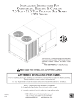
FIGURE 5 - Roof Curb and
Duct Opening Dimensions
IMPORTANT NOTES: Area enclosed by roof
curb must comply with clearance to combustible
materials. If the roof is constructed of combustible
materials, area within the roof curb must be
ventilated, left open, or covered with non-
combustible material which has an "R" value of
at least 5. If area within curb is left open, higher
radiated sound levels may result.
If area inside curb is open, roof opening
dimensions must be no greater than:
Cabinet A - 34-13/16" x 69" (884 x 1753mm);
Cabinet B - 49-13/16" x 69" (1265 x 1753mm);
Cabinet C - 61-5/16" x 97-7/8" (1557 x 2486mm).
NOTE: See Appendix, page 58, for cross-reference
by Model Size and Cabinet Size.
Dimensions - Downow Roof Curb Option CJ31
Cabinet
Size
RCA Model Size RDA Model Size
Illustration Codes - FIGURE 5
A B C D E F G H J K L M
Curb Dimensions for Cooling Only Model RCA, RDA by Cabinet Size, Model Size - inches (±1/8)
A
025, 037, 059, 060, 077, 078, 090, 108, 109, 120 102, 114, 126, 144 6-1/8 26-1/2 24 12 24 12 38-5/8 13-1/4 17-1/2 12-7/8 72-3/4 12-1/4
164
--
N/A N/A 24 12 24 12 38-5/8 13-1/4 17-1/2 12-7/8 72-3/4 12-1/4
B 078, 090, 108, 120, 139, 166, 184, 198 102, 114, 126, 144, 188, 220, 234 N/A N/A 36 12 36 12 53-5/8 13-1/4 17-1/2 12-7/8 72-3/4 12-1/4
C
176, 226 230, 280 19-3/8 32-3/8 30 18 46 15 65-1/8 20-1/4 24-3/4 17-7/8 101-5/8 13-1/4
292, 374 346, 428, 446 10-3/4 49-1/2 47 18 46 15 65-1/8 20-1/4 24-3/4 17-7/8 101-5/8 13-1/4
Curb Dimensions for Cooling Only Model RCA, RDA by Cabinet Size, Model Size - mm (±3)
A
025, 037, 059, 060, 077, 078, 090, 108, 109, 120 102, 114, 126, 144 156 673 610 305 610 305 981 337 445 327 1848 311
164
--
N/A N/A 610 305 610 305 981 337 445 327 1848 311
B 078, 090, 108, 120, 139, 166, 184, 198 102, 114, 126, 144, 188, 220, 234 N/A N/A 914 305 914 305 1362 337 445 327 1848 311
C
176, 226 230, 280 492 822 762 457 1168 381 1654 514 629 454 2581 337
292, 374 346, 428, 446 273 1257 1194 457 1168 381 1654 514 629 454 2581 337
When cutting only duct openings, cut opening 1" (25mm) larger than duct size to allow clearance for installation.
Cabinet
Size *
RDCA Model Size* RDDA, Model Size*
Gas Heat
Size *
Illustration Codes - FIGURE 5
A B C D E F G H J K L M
Curb Dimensions for Cooling/Gas Heat Makeup Air Model RDCA, RDDA by Cabinet Size, Model Size - inches (±1/8)
A
025, 037, 059, 060,
077, 078, 090, 108,
109, 120, 164
102, 114, 126, 144
100 9-7/8 19 18 12 24 12 38-5/8 13-1/4 17-1/2 12-7/8 72-3/4 12-1/4
150 6-1/8 26-1/2 24 12 24 12 38-5/8 13-1/4 17-1/2 12-7/8 72-3/4 12-1/4
200 N/A N/A 24 12 24 12 38-5/8 13-1/4 17-1/2 12-7/8 72-3/4 12-1/4
B
078, 090, 108, 120,
139, 166, 184, 198
102, 114, 126, 144,
188, 220, 234
250 6-1/8 41-1/2 36 12 36 12 53-5/8 13-1/4 17-1/2 12-7/8 72-3/4 12-1/4
300 N/A N/A 36 12 36 12 53-5/8 13-1/4 17-1/2 12-7/8 72-3/4 12-1/4
C 176, 226, 292, 374
230, 280, 346, 428,
446
350, 400 19-3/8 32-3/8 30 18 46 15 65-1/8 20-1/4 24-3/4 17-7/8 101-5/8 13-1/4
450, 500 13-1/4 44-1/2 42 18 46 15 65-1/8 20-1/4 24-3/4 17-7/8 101-5/8 13-1/4
550, 600 10-3/4 49-1/2 47 18 46 15 65-1/8 20-1/4 24-3/4 17-7/8 101-5/8 13-1/4
650, 700 8-1/4 55 52 18 46 15 65-1/8 20-1/4 24-3/4 17-7/8 101-5/8 13-1/4
Curb Dimensions for Cooling/Gas Heat Makeup Air Model RDCA, RDDA by Cabinet Size, Model Size - mm (±3)
A
025, 037, 059, 060,
077, 078, 090, 108,
109, 120, 164
102, 114, 126, 144
100 251 483 457 305 610 305 981 337 445 327 1848 311
150 156 673 610 305 610 305 981 337 445 327 1848 311
200 N/A N/A 610 305 610 305 981 337 445 327 1848 311
B
078, 090, 108, 120,
139, 166, 184, 198
102, 114, 126, 144,
188, 220, 234
250 156 1054 914 305 914 305 1362 337 445 327 1848 311
300 N/A N/A 914 305 914 305 1362 337 445 327 1848 311
C 176, 226, 292, 374
230, 280, 346, 428,
446
350, 400 492 822 762 457 1168 381 1654 514 629 454 2581 337
450, 500 337 1130 1067 457 1168 381 1654 514 629 454 2581 337
550, 600 273 1257 1194 457 1168 381 1654 514 629 454 2581 337
650, 700 210 1397 1321 457 1168 381 1654 514 629 454 2581 337
Cabinet
Size*
RECA Model Size * REDA Model Size *
* Electric
Heat Size
Illustration Codes - FIGURE 5
A B C D E F G H J K L M
Curb Dimensions for Cooling/Electric Heat Makeup Air Model RECA, REDA by Cabinet Size, Model Size - inches (±1/8)
A
025, 037, 059, 060, 077, 078, 090, 108, 109, 120, 164 102, 114, 126, 144 All N/A N/A 24 12 24 12 38-5/8 13-1/4 17-1/2 12-7/8 72-3/4 12-1/4
B
078, 090, 108, 120, 139, 166, 184, 198 102, 114, 126, 144, 188, 220, 234 All N/A N/A 36 12 36 12 53-5/8 13-1/4 17-1/2 12-7/8 72-3/4 12-1/4
C
176, 226, 292, 374 230, 280, 346, 428, 446 All 10-3/4 49-1/2 47 18 46 15 65-1/8 20-1/4 24-3/4 17-7/8 101-5/8 13-1/4
Curb Dimensions for Cooling/Electric Heat Makeup Air Model RECA, REDA by Cabinet Size, Model Size - mm (±3)
A
025, 037, 059, 060, 077, 078, 090, 108, 109, 120, 164 102, 114, 126, 144 All N/A N/A 610 305 610 305 981 337 445 327 1848 311
B
078, 090, 108, 120, 139, 166, 184, 198 102, 114, 126, 144, 188, 220, 234 All N/A N/A 914 305 914 305 1362 337 445 327 1848 311
C
176, 226, 292, 374 230, 280, 346, 428, 446 All 273 1257 1194 457 1168 381 1654 514 629 454 2581 337
* See Appendix, page 58, for cross-reference by Model Size/Heat Size and Cabinet Size
Form I-MAPS II, Page 14
FIGURE 6 - Option
CJ31 Downow Roof
Curb Cross Section
and Corner Detail
1. Position the roof curb end assemblies and side assemblies as shown in the
drawing in FIGURE 4, page 12. Fasten with bolts and lag screws as illus-
trated in the corner detail (FIGURE 6, below).
2. Attach duct sides and ends to create the internal ductwork. Use the sheet
-
metal screws to attach the ductwork pieces. (Refer to FIGURE 4). Attach
the return air duct angles to the attached end and side and to the roof curb.
NOTE: If the system does not have a return air opening, the return air duc-
twork may be installed in the curb but is not required.
3. Check the roof curb for squareness. The curb must be adjusted so that the
diagonal measurements are equal within a tolerance of ± 1/8" (3mm).
4. Level the roof curb. To ensure a good weatherproof seal between the cabi
-
net curb cap and the roof curb, the curb must be leveled in both directions
with no twist end to end. Shim as required and secure curb to the roof deck
before installing ashing (See Curb Detail in FIGURE 6).
5. Install eld-supplied ashing.
6. Before placing the unit on the curb, apply 1/4" x 1-1/4" foam sealant tape to
both the top surface of the curb rails and the top surface of the perimeter of
the duct opening(s), being sure to make good butt joints at all corners.
The sealant tape must be applied to the curb rails to prevent water leakage
into the curb area due to blown rain and capillary action.
Downow Roof Curb Assembly and Installation Instructions
















Curb Section and Corner Detail
5.2.2 Curbs for
Horizontal Airow
(Option CJ50 and
Option CJ49)
Option CJ50 is a 32" (813mm) high curb designed to provide horizontal airow
into the side of a building or at a location through the roof that is not directly
under the unit. Option CJ49 is the same design but is 36" (914mm) high. Both
curbs are NRCA approved and are constructed of 14 gauge steel with a 2x4
full perimeter wood nailer strip.
Option CJ49 and CJ50 curbs are shipped in sections and require eld assem-
bly. Position the curb so that the air inlet of the unit will not be facing into the
prevailing wind. Always comply with the clearances in Paragraph 4.3. Verify
that the curb is the correct size and follow the assembly and installation instruc-
tions shipped with the curb.
For condensate drainage and proper operation, it is important that the instal-
lation be level. To ensure a good weatherproof seal between the unit curb cap
and the curb, the curb must be leveled in both directions with no twist end to
CAUTION: Before installation, recheck to be sure that the cor-
rect curb has been ordered. Be sure that the curb selected
matches the unit ordered. Verify the dimensions of the curb
received with the dimension table in FIGURE 5.
5.2.1 Downow Roof
Curb, Option CJ31
(cont'd)
5. Mounting (cont'd)
5.2 Roof Curb
(cont'd)


















Typical Curb
Detail
Form I-MAPS II, P/N 206131 (Rev 13), Page 15
Option CJ50 for
Models RCA, RDA,
RECA, REDA
Cabinet Size* P/N
Option CJ50 for
Models RDCA and
RDDA
with Gas Heat Section Size
A 206116
100 150 200 250 300 350 400 450 500 550 600 650 700
B 206118
C 208944 206116 206118 208944
Option CJ49 for
Models RCA, RDA,
RECA, REDA
Cabinet Size* P/N
Option CJ49 for
Models RDCA and
RDDA
with Gas Heat Section Size
C 208943
100 150 200 250 300 350 400 450 500 550 600 650 700
N/A 208943
*See cross-reference by Model Size and Cabinet Size in the APPENDIX, page 58.






















































FIGURE 7A - P/N's, Dimensions, and Airow of Horizontal Curbs, Option CJ50 and CJ49
Dimensions are shown by Cabinet Size; see cross-reference of cabinet size and model size,
Appendix, page 58.
Dimensions
Dimensions of Horizontal Airow Curb, Options CJ49 and CJ50, by Cabinet Size - inches (±1/8)
Cabinet Size A B C D E F G H J K L M N P
A 24 22-15/16 17-13/32 15 34-13/16 38-9/16 32 18 72-3/4 69 11-3/8 17-1/2 29-1/8 11-1/8
B 36 37-15/16 24-29/32 22-1/2 49-13/16 53-9/16 32 18 72-3/4 69 11-3/8 17-1/2 29-1/8 11-1/8
C 52 50-3/8 32-1/2 28-1/4 61-11/32 65-3/32
32 (CJ50) 18 (CJ50)
101-37/64 97-7/8 18-7/16 24-3/4 38-5/8 16
36 (CJ49) 22 (CJ49)
Dimensions of Horizontal Airow Curb, Options CJ49 and CJ50, by Cabinet Size - mm (±3)
Cabinet Size A B C D E F G H J K L M N P
A 610 583 442 381 884 979 813 457 1848 1753 289 445 740 283
B 914 964 633 572 1265 1360 813 457 1848 1753 289 445 740 283
C 1321 1280 826 718 1558 1653
813 (CJ50) 457 (CJ50)
2580 2486 468 629 981 406
914 (CJ49) 559 (CJ49)
end. Shim as required and secure curb before installing ashing. Flashing is
eld supplied.
If Option CJ50 or CJ49 curb was ordered to arrive prior to the heater, it will be
identied by the following P/N's. Verify the appropriate P/N before installing the
curb.
Before placing the unit on the curb, apply 1/4" x 1-1/4" foam sealant tape to
both the top surface of the curb sides and the top surface of the perimeter of
the duct opening(s), being sure to make good butt joints at all corners.
Option CJ50 and CJ49 curbs should only be used for the Models and Sizes for
which they are designed. The supply duct panels are insulated so should not
be used in an installation that prohibits insulation in the supply duct.
Horizontal Airow
Roof Curb P/N's
Form I-MAPS II, Page 16























Assembly and Installation Instructions for Option CJ49 and CJ50,
Curbs for Horizontal Airow
CAUTION: Before installing, recheck to be sure that the cor-
rect curb has been ordered and received. Be sure that the
curb selected matches the unit ordered. Verify the dimen-
sions of the curb received with the dimension table in FIG-
URE 7A.
Verify all the components and be sure that the curb is correct for the system
being installed. A short version of the installation instructions is included in this
manual. When assembling, follow the complete step-by-step illustrated instruc-
tions included with the curb.
FIGURE 7B - Exploded
View of Horizontal Airow
Curb Assembly Showing
all Components
Instructions
Layout the four curb sides.
Join the corners using six of the
bolts and washer sets at each corner.
Be sure curb assembly is square.
Line up the holes and use the screws in the
hardware kit to attach the component parts in
the following order:
1 - Two bottom support braces
2 - Divider panel
3 - 3 Bottom panels (supply bottom 1 and 2 and
return bottom)
4 - Supply duct divider
5 - Return divider - 1
6 - Supply duct top panel
7 - Return divider - 2
8 - Return air cover (Install only if the application
does not require return air. If the application
includes return air, this cover is not used.)
Complete curb installation with the following eld sup-
plied items: counter ashing, roong felt, rigid insulation,
and cant strip. See FIGURE 7C.
Before placing the unit on the curb, apply the 3/4" x
1-1/4" gasket to both the top surface of the curb rails and
the top surface of the perimeter of the duct opening(s),
being sure to make good butt joints at all corners.





















FIGURE 7C -
Curb Detail
Hardware Package
Qty Description
24 1/4-20 x 1/2 Hex Bolts with Nuts
24 1/4 Split Lock Washers
24 1/4 Flat Washers
88 10-16 x 1/2 Hex Screws
1 3/4" x 1-1/4" x 14' Gasket
5.2.2 Curbs for
Horizontal Airow
(Option CJ50 and
Option CJ49) (cont'd)
5. Mounting (cont'd)
5.2 Roof Curb
(cont'd)
Form I-MAPS II, P/N 206131 (Rev 13), Page 17
5.3 Duct Furnace
Curb Section,
Model JHUP-
0250
If a Model JHUP-0250 duct furnace curb section in included in the installation, it
must be set on a Cabinet B roof curb before placing the Model RDDA or Model
RDCA system. Verify that gasketing has been applied to the top surfaces of
the installed roof curb. Using all four lifting lugs and being sure the ductwork
matches, set the duct furnace curb section on the roof curb. Refer to FIGURE
8 and the lifting information in Paragraph 5.4.
Gas Supply Entrance
Duct Furance
Access Panel
Door Handle
Limit Control Access Panel
(4) Lifting Lugs
Corner
“W”
Corner
“Z”
Corner
“X”
Corner “Y”
FIGURE 8 - Set a
Model JHUP-0250
Duct Furnace Curb
Section directly on
the Roof Curb
5.4 Rigging and
Lifting the Unit
DANGER: If there is any visible damage or any question about
the integrity of the lifting lugs, DO NOT LIFT the system. Con-
sult the factory. See Hazard Intensity Levels, page 2.
See approximate net weights in Paragraph 5.1. If corner weights are required,
refer to Sales/Technical Catalog Form C-PC (available on the Website, www.
RezSpec.com). IMPORTANT NOTE: "C" Cabinet systems MUST be loaded
and unloaded by the lifting lugs. Due to size, DO NOT attempt to move a "C"
cabinet system with a fork lift.
Check to be sure that gasketing has been applied to the curb or duct furnace
curb section prior to lifting the unit.
Lifting lugs are provided for rigging. Cabinets A and B have four lifting lugs --
one on each corner. Cabinet C has six lifting lugs -- three on each side. Inspect
the lugs and their attachment points. If there is any doubt about the integrity of
the lifting lugs or their attachment points, contact the factory.
DANGER: To prevent injury, death, or equipment damage
when lifting, use ALL lifting lugs. See Hazard Intensity Lev-
els, page 2.
The unit MUST be lifted with appropriate spreader bars that lift the unit straight
up with vertical force only on the lifting lugs. Using ALL lifting lugs (4 or 6) is
mandatory.
Follow the wiring diagram and instructions in Paragraph 9.4 for making gas
and electrical connections.
Before setting the Model RDDA or RDCA unit on top of the duct furnace
curb section, apply gasket strips to the top perimeter and to the duct connec-
tions of the duct furnace curb section.
Corner Weights
Corner lbs kg
"W" 158 72
"X" 158 72
"Y" 107 49
"Z" 107 49
Form I-MAPS II, Page 18
6. Mechanical
6.1 Duct Connections
Requirements and
Suggestions for
Installing Ducts
Supply and optional return air duct connections are made at the curb and can
be made prior to the unit being set on the curb. See FIGURE 5 for downow
roof curb or FIGURE 7 for horizontal ow curb.
To facilitate startup, on systems with a heat section or in cooling only systems
with Option DU1, the discharge temperature sensor is factory-installed tem-
porarily in the outlet. Depending on the controls, the sensor must either be
re-located to the supply ductwork or disconnected. Because of the split burner
system, ductwork conguration and location of the sensor are especially impor-
tant on units with a gas heat section. See Paragraph 8.1 on ductwork congu-
ration requirements and instructions about re-locating the sensor.
CAUTION: An external duct system static pressure not within the
limits shown on the rating plate, or improper motor pulley or belt
adjustment, may overload the motor. See Hazard Levels, page 2.
Type of Ductwork - The type of duct installation to be used depends in
part on the type of construction of the roof (whether wood joist, steelbar
joist, steel truss, pre-cast concrete) and the ceiling (whether hung, ush,
etc.).
Ductwork Material
- Rectangular duct should be constructed of not lighter
than No. 26 U.S. gauge galvanized iron or No. 24 B & S gauge aluminum.
Ductwork Structure -
All duct sections 24 inches (610mm) or wider, and
over 48 inches (1219mm) in length, should be cross broken on top and bot-
tom and should have standing seams or angle-iron braces. Joints should
be S and drive strip, or locked.
Through Masonry Walls
- No supply air duct should come in contact with
masonry walls. Insulate around all air ducts through masonry walls with not
less than 1/2" (13mm) of insulation. 1" (25mm) is recommended.
Through Uncooled/Unheated Space
- Insulate all exposed supply air
ducts passing through an uncooled or unheated space with at least 1/2" (1"
is recommended) of insulation.
Duct Supports
- Suspend all ducts securely from buildings members. Do
not support ducts solely by the unit duct connections.
Duct Sizing
- Proper sizing of the supply air ductwork is necessary to
ensure a satisfactory installation. The recognized authority for such infor-
mation is the Air Conditioning Contractors Association, 2800 Shirlington
Road, Suite 300, Arlington, VA 22206 (www.acca.org). A manual covering
duct sizing in detail may be purchased directly from them.
Duct Connections
- To minimize sound and vibration transmission, use
exible duct connections. Ducts must be attached and sealed to provide
airtight connections.
Return Air Duct/Grill Size
- Make certain that return air ducting or grill has
a free area equal to the return duct size connection.
5.4 Rigging and
Lifting (cont'd)
5. Mounting (cont'd)
Test lift the unit to be sure that it is secure. Lift the unit slowly, following safe
lifting procedures.
Failure to lift by the manufacturer's instructions could cause damage to the
equipment and/or personal injury or death. The equipment manufacturer is not
responsible for unsafe rigging or lifting procedures.
DANGER: To prevent injury, death, or equipment damage
caused by inadequate or improper rigging, test lift the unit
before attempting to install it on the roof. See Hazard Inten-
sity Levels, page 2.
Form I-MAPS II, P/N 206131 (Rev 13), Page 19
6.2 Condensate
Drain
A slide-out, removable drain pan with a 1" male NPT drain connection is located
below the coil cabinet (See FIGURE 2A or FIGURE 2B, page 7 or 8). When
connecting the drain line, provide a means of disconnecting the line at or near
the cabinet connection to allow the drain pan to be removed for cleaning.
Ensure the system is level and install a trap in the drain (see FIGURE 9A).
Pitch the drain line at least 1/2" (13mm) for every 10 feet (3M) of horizontal run.
Drain lines must not interfere with drain pan or access panels. An obstruction
in the drain or a poorly designed drain can cause condensate pan to over ow.
Overow could result in unit or building damage.
If the installation or local code requires, run drain into a waste water system.
Condensate Drain
Trap
The design of the drain trap is important. Since the condensate drain pan is
on the blower inlet side, there is a negative pressure at the drain relative to
the ambient. The trap height must account for this static pressure difference.
Maximum negative static can be determined by reading the negative pressure
at the blower inlet and adding .2” w.c. to allow for dirty lters.
If dimension "B" in FIGURE 9A is not tall enough, the water seal will not hold,
and air will be drawn through the drain pipe into the system. If the outlet leg of
the trap is too tall, water will back up into the drain pan. As condensate forms
during normal operation, the water level in the trap rises until there is a con-
stant outow. FIGURE 9A illustrates the appropriate dimensions for trapping a
negative pressure system.






FIGURE 9B -
Drain
Trap with
Cleanout




A = 1" (25mm) for each 1"
(25mm) of maximum static
pressure plus 1" (25mm)
B = A + A/2
FIGURE 9A -
Condensate
Drain Trap
Dimensions
Improper trap design accounts for some condensate drainage system failures,
but incorrect use and maintenance of condensate drain traps can also cause
problems. The combination of airborne particles and moisture in the air han-
dler can result in algae formation in the drain pan and traps. The traps must be
cleaned regularly to avoid blockage that can slow or stop water ow, resulting
in backup into the system.
If drains have a cleanout opening (FIGURE 9B), be sure to close the opening
after cleaning.
Condensate Drain
Use
Seasonal Usage - At the beginning of the cooling season, inspect and clean
the entire cooling coil cabinet including the condensate drain pan. Thoroughly
clean dirt, algae, grease, and other contaminates. Inspect condensate drain
pans, traps, and piping; ll traps with water to ensure proper operation. During
a wintertime shutdown of the cooling system it may be desirable to disconnect
and remove all water from the traps and drains to prevent freeze damage. If
local building codes permit, traps may be lled with an antifreeze solution. Or,
piping may be designed with freeze plugs or other freeze protection methods
(such as a heat tape).
Year Round Usage - Climates or applications with cooling requirements year
round require more frequent inspections of the cooling coil cabinet and conden-
sate drains. Depending on climate, freeze protection of traps may be required
during non-cooling hours.
Form I-MAPS II, Page 20
To avoid possible damage, it is recommended that the outside air hood be
installed after the system has been placed on the roof. The air hood should be
installed before the blower is operated. Do not install the hood while the system
is in operation.
All screw ends should be inside the air hood. Remove plastic lm from painted
parts before installing. Refer to the illustration that applies:
FIGURE 10A for Cabinet Sizes A and B without a power exhaust option
FIGURE 10B for Cabinet Size A with a power exhaust option
FIGURE 10C for Cabinet Size B with a power exhaust option
FIGURE 10D for Cabinet Size C with or without a power exhaust option
(NOTE: See Model Size/Cabinet Size cross-reference tables in the Appendix
on page 58.)
Instructions (apply to all FIGURES except where noted):
1. Install Top Panel
- On the air inlet of the cabinet, remove and save the
factory-installed screws attaching the system top. Slide the hood top panel
underneath the edge of the cabinet top. The edge of the hood top panel
must be between the cabinet top and the end panel. Reinsert all of the
sheetmetal screws.
2. Install Left Side Panel (right when facing the unit)
- Locate the vertical
row of cabinet screws to the right of the opening that attach the condenser
section. Remove and save those screws.
Position the hood left side panel under and to the inside of the hood top
panel. Reinsert the screws to attach the side panel.
Attach the hood side panel to the hood top with sheetmetal screws.
3. Install Right Side Panel (left when facing the unit)
- Position the hood
right side panel under and to the inside of the hood top panel. Attach to the
unit using the required number of self-drilling screws.
4.
FIGURE 10C - Install Top Panel Slope Section - Position the slope panel
against the top panel and over the side panels. Attach to the top panel and
both sides with sheetmetal screws.
5. Install Bottom Support
- Position the hood bottom support so that it is to
the inside of the two side panels.
FIGURES 10A and 10D - Attach to the cabinet using the required number
of self-drilling screws. Attach to both side panels with sheetmetal screws.
FIGURES 10B and 10C - Attach to both side panels with sheetmetal
screws.
6. Install the Filter Assembly
FIGURE 10A, Cabinet Sizes A and B without a power exhaust option -
Attach the center support and the two side lter angles. Attach the lter
spacer with wing screw receptacle. Position the four lters in the opening.
Secure the lters with the lter clamp and the wing screws.
FIGURES 10B and 10C, Cabinet Size A or B with a power exhaust
option - Install the lter frame with lters in place. Position the lter frame
assembly in the inlet opening of the hood. Attach at the front and back
holes with 1/2" sheetmetal screws. Insert a 3/4" sheetmetal screw at each
of the center holes (one on each side).
6.3 Inlet Air Hood
The outside air inlet hood is a weatherized hood with permanent aluminum
lters, designed to be eld assembled and installed around the horizontal inlet
air opening of the cabinet.
CAUTION: It is recommended that the inlet to the outside air hood
NOT be facing into the prevailing wind. Allow 14" minimum clearance
from the bottom of the air hood to the mounting surface.
Option AS16 or
AS19, Inlet Air
Hood, Installation
Instructions
Installation NOTE:
If equipped with
a power exhaust
option, attach the
power exhaust
hood(s) before
installing the outside
air hood. See
Paragraph 9.2,
pages 38-39.
NOTES:
- Inlet air hood painted
parts are shipped with a
protective plastic cover-
ing. As parts are being
installed, remove the
protective plastic cover-
ing.
- Select screws care-
fully. Use sheetmetal
screws (slotted head
with straight tip) when
holes in the cabinet are
provided. Use self-drill-
ing screws (head is not
slotted with drill-type tip)
when cabinet holes are
not provided.
6. Mechanical
(cont'd)
  • Page 1 1
  • Page 2 2
  • Page 3 3
  • Page 4 4
  • Page 5 5
  • Page 6 6
  • Page 7 7
  • Page 8 8
  • Page 9 9
  • Page 10 10
  • Page 11 11
  • Page 12 12
  • Page 13 13
  • Page 14 14
  • Page 15 15
  • Page 16 16
  • Page 17 17
  • Page 18 18
  • Page 19 19
  • Page 20 20
  • Page 21 21
  • Page 22 22
  • Page 23 23
  • Page 24 24
  • Page 25 25
  • Page 26 26
  • Page 27 27
  • Page 28 28
  • Page 29 29
  • Page 30 30
  • Page 31 31
  • Page 32 32
  • Page 33 33
  • Page 34 34
  • Page 35 35
  • Page 36 36
  • Page 37 37
  • Page 38 38
  • Page 39 39
  • Page 40 40
  • Page 41 41
  • Page 42 42
  • Page 43 43
  • Page 44 44
  • Page 45 45
  • Page 46 46
  • Page 47 47
  • Page 48 48
  • Page 49 49
  • Page 50 50
  • Page 51 51
  • Page 52 52
  • Page 53 53
  • Page 54 54
  • Page 55 55
  • Page 56 56
  • Page 57 57
  • Page 58 58
  • Page 59 59
  • Page 60 60
  • Page 61 61
  • Page 62 62
  • Page 63 63
  • Page 64 64

Reznor RCA Installation guide

Category
Heat pumps
Type
Installation guide
This manual is also suitable for

Ask a question and I''ll find the answer in the document

Finding information in a document is now easier with AI