P-MAPS II, PN 271467R1, Page 3
Serial No. Date of
Manufacture
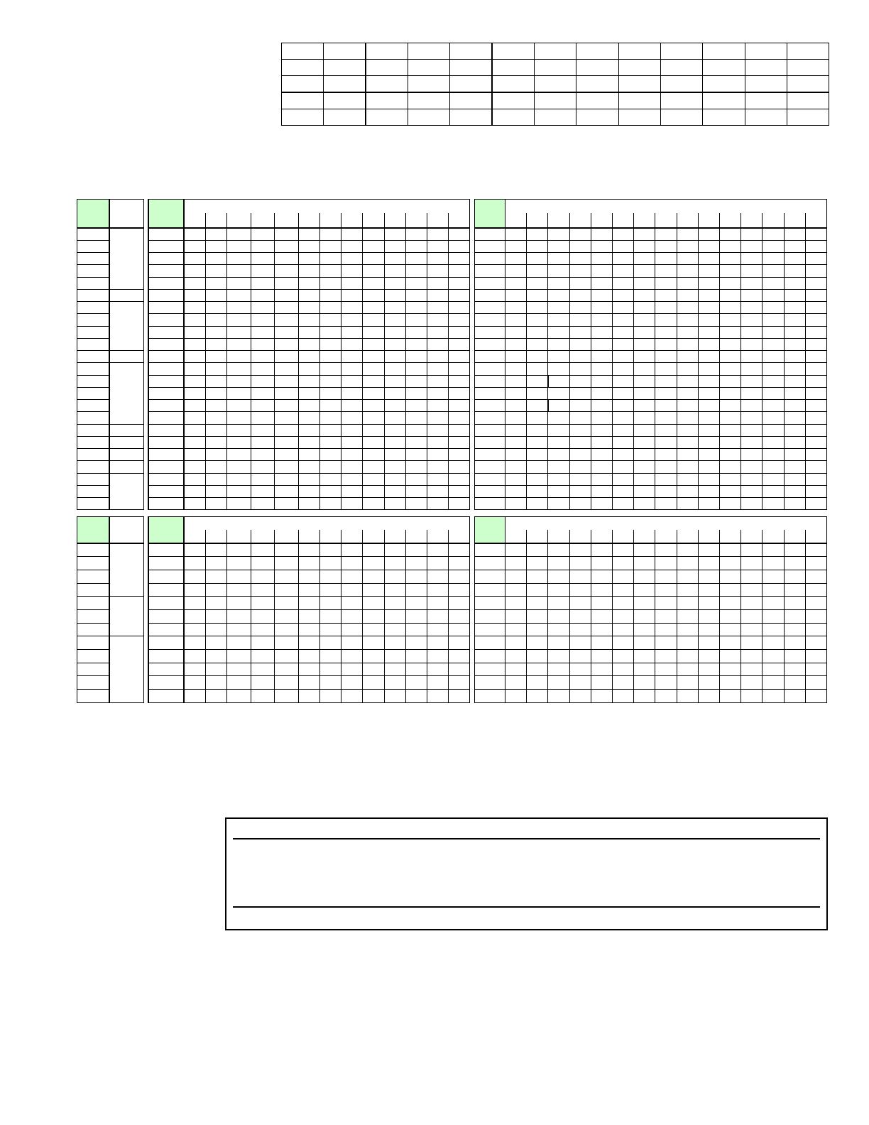
Cross-Reference by Model/Size and Cabinet Size
Because of the numerous model/size combinations, some replacement parts are listed by Cabinet Size A, B, or C.
Year Jan Feb Mar Apr May June July Aug Sept Oct Nov Dec
2005 BEA BEB BEC BED BEE BEF BEG BEH BEI BEJ BEK BEL
2006 BFA BFB BFC BFD BFE BFF BFG BFH BFI BFJ BFK BFL
2007 BGA BGB BGC BGD BGE BGF BGG BGH BGI BGJ BGK BGL
2008 BHA BHB BHC BHD BHE BHF BHG BHH BHI BHJ BHK BHL
Model
RCA
Cabinet
Size
Model
RDCA
Gas Heat Section Size
Model
RECA
Electric Heat Module
-100 -150 -200 -250 -300 -350 -400 -450 -500 -550 -600 -650 -700 -05S -10S -15S -20S -24S -15 -20 -25 -30 -35 -39 -50 -60 -75 -88
025
A
025
A A A -- -- -- -- -- -- -- -- -- --
025
A A A A A A A A A A A -- -- -- --
037 037
A A A B B -- -- -- -- -- -- -- --
037
-- A A A A A B A A B A B B B B
055 055
A A A B B -- -- -- -- -- -- -- --
055
-- -- A A A A B A A B A B B B B
059 059
A A A -- -- -- -- -- -- -- -- -- --
059
-- A A A A A A A A A A -- -- -- --
060 060
A A A -- -- -- -- -- -- -- -- -- --
060
A A A A A A A A A A A -- -- -- --
075
B
075
-- -- -- B B -- -- -- -- -- -- -- --
075
-- -- -- -- -- B B B B B B B B B B
077
A
077
A A A -- -- -- -- -- -- -- -- -- --
077
-- A A A A A A A A A A -- -- -- --
078 078
A A A B B -- -- -- -- -- -- -- --
078
A A A A A A B A A B A B B B --
085 085
A A A -- -- -- -- -- -- -- -- -- --
085
-- A A A A A A A A A A -- -- -- --
090 090
A A A B B -- -- -- -- -- -- -- --
090
-- A A A A A B A A B A B B B B
091
B
091
-- -- -- B B -- -- -- -- -- -- -- --
091
-- -- -- -- -- -- B B B B B B B B B
108
A
108
A A A B B -- -- -- -- -- -- -- --
108
-- A A A A A B A A B A B B B B
109 109
A A A B B -- -- -- -- -- -- -- --
109
-- -- A A A A B A A B A B B B --
120 120
A A A B B -- -- -- -- -- -- -- --
120
-- A A A A A B A A B A B B B B
139 139
B B B B B -- -- -- -- -- -- -- --
139
-- -- A A A A B A A B A B B B B
164 164
A A A -- -- -- -- -- -- -- -- -- --
164
-- -- A A A A A A A A A -- -- -- --
166
B
166
-- -- -- B B -- -- -- -- -- -- -- --
166
-- -- -- -- -- B B B B B B B B B B
176
C
176
-- -- -- -- -- C C C C C C C C
176
-- -- -- -- -- -- -- -- -- -- C C C C C
184
B
184
-- -- -- B B -- -- -- -- -- -- -- --
184
-- -- -- -- -- B B B B B B B B B B
198
B
198
-- -- -- B B -- -- -- -- -- -- -- --
198
-- -- -- -- -- B B B B B B B B B B
226
C
226
-- -- -- -- -- C C C C C C C C
226
-- -- -- -- -- -- -- -- -- -- C C C C C
292 292
-- -- -- -- -- C C C C C C C C
292
-- -- -- -- -- -- -- -- -- -- C C C C C
374 374
-- -- -- -- -- C C C C C C C C
374
-- -- -- -- -- -- -- -- -- -- C C C C C
Model
RDA
Cabinet
Size
Model
RDDA
Gas Heat Section Size
Model
REDA
Electric Heat Module
-100 -150 -200 -250 -300 -350 -400 -450 -500 -550 -600 -650 -700 -05S -10S -15S -20S -24S -15 -20 -25 -30 -35 -39 -50 -60 -75 -88
102
A
102
A A A B B -- -- -- -- -- -- -- --
102
-- A A A A A B A A B A B B B
B
114 114
A A A B B -- -- -- -- -- -- -- --
114
-- A A A A A B A A B A B B B
B
126 126
A A A B B -- -- -- -- -- -- -- --
126
-- A A A A A B A A B A B B B
B
144 144 A
A A B B -- -- -- -- -- -- -- --
144
-- A A A A A B A A B A B B B
B
188
B
188
-- -- -- B B -- -- -- -- -- -- -- --
188
-- -- -- -- -- B B B B B B B B B
B
220 220
-- -- -- B B -- -- -- -- -- -- -- --
220
-- -- -- -- -- B B B B B B B B B
B
234 234
-- -- -- B B -- -- -- -- -- -- -- --
230
-- -- -- -- -- -- -- -- -- -- C C C C C
230
C
230
-- -- -- -- -- C C C C C C C C
234
-- -- -- -- -- B B B B B B B B B B
280 280
-- -- -- -- -- C C C C C C C C
280
-- -- -- -- -- -- -- -- -- -- C C C C C
346 346
-- -- -- -- -- C C C C C C C C
346
-- -- -- -- -- -- -- -- -- -- C C C C C
428 428
-- -- -- -- -- C C C C C C C C
428
-- -- -- -- -- -- -- -- -- -- C C C C C
446 446
-- -- -- -- -- C C C C C C C C
446
-- -- -- -- -- -- -- -- -- -- C C C C
C
References
Printed Forms (Download from Website listed below.) .....................................Form ...................P/N
Installation Manual for MAPS
®
II Models ..........................................................I-MAPSII ...............206131
Operation/Maintenance/Service Manual for MAPS
®
II Models ........................ O-MAPSII .............. 209179
Control Instructions, Control Option D12 with FX05 ............................ CP-MAPS-D12 w/FX05 ...209341
Control Instructions, Control Option D12A with FX06 ......................... CP-MAPS-D12A w/FX06 ..206137
Website ....................................................................................................................www.RezSpec.com