Page is loading ...

INSTALLATION INSTRUCTIONS
RESIDENTIAL USE ONLY
INSTALLER: LEAVE THIS MANUAL WITH THE HOMEOWNER.
READ AND SAVE THESE INSTRUCTIONS
07959 rev. G
MODELS
NRFLOH-ND
VSMARTH-ND
NRFLOH
VSMARTH
ENERGY EFFICIENT FRESH AIR SYSTEM
VB0113
NRFLOE
VSMARTE

ABOUT THIS MANUAL
First, we want to congratulate you on your purchase of this excellent unit which will allow you and your family to enjoy clean and healthy
air throughout your home for years to come!
Please take note that this manual uses the following symbols to emphasize particular information:
NOTE: Indicates supplementary information needed to fully complete an instruction.
WARNING
Identifies an instruction which, if not followed, might cause serious personal injuries including possibility of death.
0
!
CAUTION
Denotes an instruction which, if not followed, may severely damage the unit and/or its components.
- 2 -
ABOUT THESE UNITS
WARNING
TO REDUCE THE RISK OF FIRE, ELECTRIC SHOCK, OR INJURY TO PERSON(S) OBSERVE THE FOLLOWING:
1. This unit is intented for residential installation only.
2. Installation must be done by qualified service personnel in accordance with all applicable codes and standards, including
fire-rated construction codes and standards.
3. This unit is not designed to provide combustion and/or dilution air for fuel-burning appliances.
4. Do not install in a cooking area or connect directly to an appliance.
5. Before servicing or cleaning the unit, disconnect power from HVAC system.
6. When cutting or drilling into wall or ceiling, do not damage electrical wiring or other hidden utilities.
7. Do not use this unit with any solid-state speed control device. Use only with controller 15045 provided with the unit.
8. This unit must be installed in a weatherized location, out of direct sunlight and protected from the elements.
9. Use this unit only in the manner intended by the manufacturer. If you have questions, contact the manufacturer at the
address or telephone number listed in the warranty.
10. When performing installation, servicing or cleaning the unit, it is recommended to wear safety glasses and gloves.
11. Servicing shall be done by qualified service personnel.
12. When applicable local regulations comprises more restrictive installation and/or certification requirements,
the aforementioned requirements prevail on those of this document and the installer agrees to conform to these at his
own expenses.
CAUTION
1. For general ventilation use only. Do not use to exhaust hazardous or explosive materials and vapors.
2. Intended for residential installation only in accordance with the requirements of NFPA 90B and in compliance with all local
and national codes that are applicable.
3. Be sure to duct air outside. Do not intake/exhaust air into spaces within walls or ceiling or into attics, crawl spaces, or
garage.
4. To avoid premature clogged filter, turn OFF the unit during construction or renovation.
5. Please read the unit specification label on the product for further information and requirements.
6. At least once a year, the unit mechanical and electronic parts should be inspected by qualified service personnel.
7. This unit must be connected to a 24-volt class 2 circuit only.
0
!
NOTE: The fanless energy recovery ventilator NRFLOE or VSMARTE is designed to assist in the management of humidity introduced
into the home. In extreme humidity conditions, the use of additional dehumidification may be desirable. Quickly remove all
excess moisture and keep areas clean.

1. SERVICE PARTS . . . . . . . . . . . . . . . . . . . . . . . . . . . . . . . . . . . . . . . . . . . . . . . . . . . . . . . . . . . . . . .4
2. D
IMENSIONS . . . . . . . . . . . . . . . . . . . . . . . . . . . . . . . . . . . . . . . . . . . . . . . . . . . . . . . . . . . . . . . . . .4
3. SPECIFICATIONS . . . . . . . . . . . . . . . . . . . . . . . . . . . . . . . . . . . . . . . . . . . . . . . . . . . . . . . . . . . . . . .4
4. TYPICAL INSTALLATION . . . . . . . . . . . . . . . . . . . . . . . . . . . . . . . . . . . . . . . . . . . . . . . . . . . . . . . . . . .5
5. B
EFORE STARTING . . . . . . . . . . . . . . . . . . . . . . . . . . . . . . . . . . . . . . . . . . . . . . . . . . . . . . . . . . . .5-6
5.1 INSPECT THE CONTENT OF THE BOX . . . . . . . . . . . . . . . . . . . . . . . . . . . . . . . . . . . . . . . . . . . . . . . . . . . . . . . . . . .5
5.2 T
OOLS AND MATER IA LS . . . . . . . . . . . . . . . . . . . . . . . . . . . . . . . . . . . . . . . . . . . . . . . . . . . . . . . . . . . . . . . . . . . .5
5.3 LOCATING THE UNIT . . . . . . . . . . . . . . . . . . . . . . . . . . . . . . . . . . . . . . . . . . . . . . . . . . . . . . . . . . . . . . . . . . . . . . .6
6. INSTALLATION CONFIGURATIONS . . . . . . . . . . . . . . . . . . . . . . . . . . . . . . . . . . . . . . . . . . . . . . . . . . . .6
7. I
NSTALL THE UNIT . . . . . . . . . . . . . . . . . . . . . . . . . . . . . . . . . . . . . . . . . . . . . . . . . . . . . . . . . . . . .6-8
7.1 FRESH AIR SUPPLY PORT LOCATION . . . . . . . . . . . . . . . . . . . . . . . . . . . . . . . . . . . . . . . . . . . . . . . . . . . . . . . . .6-7
7.2 BRACKETS INSTALLATION . . . . . . . . . . . . . . . . . . . . . . . . . . . . . . . . . . . . . . . . . . . . . . . . . . . . . . . . . . . . . . . . . .7-8
7.3 F
RESH AIR SUPPLY PORT OPENING . . . . . . . . . . . . . . . . . . . . . . . . . . . . . . . . . . . . . . . . . . . . . . . . . . . . . . . . . . .8
7.4 HANG THE UNIT . . . . . . . . . . . . . . . . . . . . . . . . . . . . . . . . . . . . . . . . . . . . . . . . . . . . . . . . . . . . . . . . . . . . . . . . . .8
8. CONNECTING THE DRAIN . . . . . . . . . . . . . . . . . . . . . . . . . . . . . . . . . . . . . . . . . . . . . . . . . . . .9
9. D
UCTING . . . . . . . . . . . . . . . . . . . . . . . . . . . . . . . . . . . . . . . . . . . . . . . . . . . . . . . . . . . . . . . . . .9-10
9.1 INSTALLING NON-INSULATED DUCT . . . . . . . . . . . . . . . . . . . . . . . . . . . . . . . . . . . . . . . . . . . . . . . . . . . . . . . . . . . . .9
9.2 C
ONNECTING THE INSULATED DUCTS TO THE UNIT . . . . . . . . . . . . . . . . . . . . . . . . . . . . . . . . . . . . . . . . . . . . . . . .10
10. INSTALL EXTERIOR HOOD(S) . . . . . . . . . . . . . . . . . . . . . . . . . . . . . . . . . . . . . . . . . . . . . . . . . .10-11
10.1 INSTALLING THE TANDEM® TRANSITION KIT . . . . . . . . . . . . . . . . . . . . . . . . . . . . . . . . . . . . . . . . . . . . . . . . . . . . . . 10
10.2 I
NSTALLING TWO EXTERIOR HOODS . . . . . . . . . . . . . . . . . . . . . . . . . . . . . . . . . . . . . . . . . . . . . . . . . . . . . . . . . . .11
11. 15045 OR 16629 CONTROLLER INSTALLATION . . . . . . . . . . . . . . . . . . . . . . . . . . . . . . . . . . . . . . . . .12
12. WIRING DIAGRAM . . . . . . . . . . . . . . . . . . . . . . . . . . . . . . . . . . . . . . . . . . . . . . . . . . . . . . . . . . . . .13
13. A
IR FLOW BALANCING . . . . . . . . . . . . . . . . . . . . . . . . . . . . . . . . . . . . . . . . . . . . . . . . . . . . . . . . . .14
14. 15045 OR 16629 CONTROLLER . . . . . . . . . . . . . . . . . . . . . . . . . . . . . . . . . . . . . . . . . . . . . . . .15-16
14.1 UNDERSTANDING CONTROLLER CHART . . . . . . . . . . . . . . . . . . . . . . . . . . . . . . . . . . . . . . . . . . . . . . . . . . . . . . . . . 15
14.2 O
PERATING MODES . . . . . . . . . . . . . . . . . . . . . . . . . . . . . . . . . . . . . . . . . . . . . . . . . . . . . . . . . . . . . . . . . . . . . .15
14.3 P
ROGRAMMING CONTROLLER . . . . . . . . . . . . . . . . . . . . . . . . . . . . . . . . . . . . . . . . . . . . . . . . . . . . . . . . . . . . . . .16
15. TROUBLESHOOTING . . . . . . . . . . . . . . . . . . . . . . . . . . . . . . . . . . . . . . . . . . . . . . . . . . . . . . . . . . . .16
16. W
ARRANTY . . . . . . . . . . . . . . . . . . . . . . . . . . . . . . . . . . . . . . . . . . . . . . . . . . . . . . . . . . . . . . . . . .17
APPENDIX A . . . . . . . . . . . . . . . . . . . . . . . . . . . . . . . . . . . . . . . . . . . . . . . . . . . . . . . . . . . . . . . . . . . . .18
TABLE OF CONTENTS
- 3 -

1. SERVICE PARTS
VL0030
4
3
2
1
2. DIMENSIONS
20¼”
12¼”
23¼”
27
5
8
”
Motorized damper
cable, 6’
6”
Typ.
VK0061A
NOTE: Drain fittings on
HRV units only.
3. SPECIFICATIONS
MODELS NRFLOH NRFLOE NRFLOH-ND
see NOTE 1
VSMARTH VSMARTE VSMARTH-ND
see NOTE 1
WEIGHT 27 LB 32 LB 27 LB
PORT DIAMETER 6” 6” 6”
DRAIN DIAMETER ½” N/A ½”
INSTALLATION BRACKETS*BRACKETS*BRACKETS*
ELECTRICAL SUPPLY 24 VOLTS, AC 24 VOLTS, AC N/A
POWER CONSUMPTION 5 VA 5 VA N/A
* PART NOT SHOWN.
We have a phone line dedicated exclusively to installers. For assistance, call on weekdays, 8:00 a.m. to 5:00 p.m. (Eastern Standard Time).
NOTE: Do not call these numbers for ordering parts!
TO ORDER PARTS, CONTACT YOUR LOCAL DISTRIBUTOR.
EXCLUSIVELY FOR NRFLOH NRFLOE AND NRFLOH-ND UNITS: 1-800-649-0372
EXCLUSIVELY FOR VSMARTH, VSMARTE AND VSMARTH-ND UNITS: 1-888-908-2633
- 4 -
OUTSIDE TEMPERATURE DEFROST CYCLES* (MINUTES)
CELSIUS (°C) FAHRENHEIT (°F) DEFROSTING OPERATION TIME (BETWEEN EACH DEFROST CYCLE)
-5
TO -27 23 TO -17 10 25
-27 AND LESS -17 AND LESS 10 22
No. Description
PART
NUMBER
NRFLOH
NRFLOE
VSMARTH
VSMARTE
NRFLOH-ND
VSMARTH
-ND
1 Double collar port 15745 1 1 1
2 Damper actuator 15746 1 1 -
3 Damper kit 15747 1 1 -
4 Filter 15748 1 1 1
5 Thermistor kit* 15749 1 1 -
6 Controller*
15045
16629
1
-
-
1
-
-
*provided with the unit
*applicable only for NRFLOH, NRFLOE, VSMARTH and VSMARTE units.
CAUTION
For NRFLOH-ND and VSMARTH-ND units only, when the outside temperature is under -10°C (14°F), the furnace must operate
intermittently in heating mode to prevent frost accumulation inside the unit.
NOTE 1:

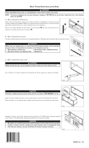
4. TYPICAL INSTALLATION
The figure below illustrates a typical installation. In every case, the fresh air to building port of the unit must be connected to the return
duct (plenum) of the furnace/air handler. The stale air from inside the duct must be connected to the supply duct of the furnace/air handler.
All units are mounted to the forced air unit return duct using provided brackets.
NOTE: For more details, see Point 7.4 in Section 7 INSTALL THE UNIT.
In every case, a range hood should be used to exhaust stale air from a cooking area.
- 5 -
A part of the stale air coming from the
supply duct of the furnace/air handler is
exhausted to the outside.
Outside fresh air is supplied to the return
duct of the furnace/air handler. See figure
at right.
NOTE: Home with multiple furnace/air
handler systems should have
1 unit on each system.
VH0064
All units can be installed in the attic. In this particular case, precautions must be followed:
1. Due to the potential temperature difference between the attic and the rest of the house, all unit ducts must be insulated.
2. The attic temperature must always be above 0°C (32°F).
CAUTION
5. BEFORE STARTING
5.1 INSPECT THE CONTENT OF THE BOX
• Inspect the exterior of the unit and components for shipping damages. Ensure that there is no damage to the ports, controller, etc.
• Inspect the interior of the unit for damages. Ensure that heat or energy recovery core, insulation, dampers, filter etc. are all intact.
5.2 TOOLS AND MAT ERIA LS
Here are the tools and materials needed to perform the installation:
- Electric drill with Phillips bit no. 2
- Tin snips or metal shear
- Cutter pliers
- Long nose pliers
- Utility knife (to cut duct tape and styrofoam)
- Aluminum duct tape
- 24-Volt class 2 transformer (NRFLOH, NRFLOE, VSMARTH and VSMARTE units only).
- 22-AWG 4-wire cable (any UL Listed (DUZX) – Type CM or CMP for U.S. A., and CSA type CMG, FT-1 or FT-4 for Canada)
(NRFLOH, NRFLOE, VSMARTH and VSMARTE units only).
- Jig saw
- Caulking gun and caulking
WARNING
To avoid risk of suffocation, discard the plastic bag wrapping the unit’s component.
0
!

5. BEFORE STARTING (CONT’D)
5.3 LOCATING THE UNIT
Choose an appropriate location for the unit.
• Close to an exterior wall, so as to limit the length of the insulated flexible duct to and from the unit.
• Close to a drain. If no drain is close by, use a pail to collect run-off (for NRFLOH and VSMARTH HRV units only).
6. INSTALLATION CONFIGURATION
For more convenience, the unit fresh air supply port can be located on top or either at right or left side of the unit. The illustrations below
show 3 configuration types:
NOTES: 1.Side configuration (type A) applies either for right or left side port.
2.The unit can also be installed hung to the joist, or mounted to the wall. In these cases, the installation kit with port
and chains in now included with the unit.
RETURN
A
VH0065A
RETURN
B
VH0066A
RETURN
C
VH0067A
SIDE CONFIGURATION
PERPENDICULAR CONFIGURATIONPARALLEL CONFIGURATION
7. INSTALL THE UNIT
7.1 FRESH AIR SUPPLY PORT LOCATION
Although the following shows how to prepare the opening on top of the unit, the procedure is the same for
the ones located on sides of the unit.
Using cutter pliers, remove the octogonal knock-out of the chosen opening.
Insert the blade of a utility knife (5/8” long maximum) in the groove to cut off the insulating foam.
Carefully remove the foam circle.
VR0011
- 6 -
VR0012A
5/8”
MAX.
CAUTION
In order to prevent damages to the unit inner components, never use a blade longer than 5/8” to cut off the insulating foam.

7. INSTALL THE UNIT (CONT’D)
7.1 FRESH AIR SUPPLY PORT LOCATION (CONT’D)
A
LL CONFIGURATIONS (A, B AND C)
Peel off the backing paper covering the sticky side of one
of the included foam gasket and stick it over the fresh air supply port opening.
P
ARALLEL AND PERPENDICULAR CONFIGURATIONS ONLY (B AND C)
Peel off the backing paper covering the sticky side of the other included foam gasket and stick it
upon the first foam gasket.
VJ0053
7.2 BRACKETS INSTALLATION
Three brackets are supplied with the unit; one hanger and two standard. See illustration
beside.
VR0014
HANGER
BRACKET
STANDARD
BRACKETS
STANDARD BRACKETS
According to the configuration chosen, install the standard brackets as follows:
• Configuration A (Side) needs one standard bracket installed below the unit, and the other one installed on top of unit, towards the
same side of the fresh air supply port.
• Configuration B (Parallel) needs one standard bracket installed on the opposite side of the hanger bracket, and the other one is
located near the fresh air supply port.
• Configuration C (Perpendicular) needs both standard brackets, installed on each side of the unit.
See illustration below.
VR0017
A
B
C
- 7 -
HANGER BRACKET
If parallel (B) or perpendicular (C) configuration is chosen, the hanger
bracket must be modified. Using long nose pliers, bend the foldable part of
the bracket at 90° towards its inner side. See illustration beside.
VR0015

7.2 BRACKETS INSTALLATION (CONT’D)
Install the included template corresponding to the chosen configuration on the furnace/air handler return duct. The minimum linear
distance between the opening and the furnace/air handler unit return opening must comply with your local building code. According to
your furnace/air handler ducts position, choose the most convenient configuration type.
Using provided metal screws, mount the hanger bracket to the return duct, on the
location shown on the template. In side configuration (A), install the unchanged
hanger bracket. In parallel or perpendicular configuration, lean the folden part of
the modified hanger bracket on the bottom edge of the return duct to ensure its
proper location. See illustration beside.
VR0016
7.3 FRESH AIR SUPPLY PORT OPENING
Using the template, trace a round opening on the furnace/air handler return duct.
Cut out the round opening traced on the furnace/air handler return duct.
VR0013
WARNING
When performing duct connections, always use approved tools and materials. Respect all corresponding laws and/or safety
regulations. Please refer to your local building code.
0
!
WARNING
Using the adjustment slots on standard brackets, make sure the foam gasket seals completely the round duct opening. Then,
permanently secure the standard brackets on unit using one screw in one center hole.
0
!
- 8 -
7. INSTALL THE UNIT (CONT’D)
7.4 HANG THE UNIT
Remove the template from the duct and hang the unit to the hanger bracket.
Then, use the provided screws and the standard bracket(s) mounted on the unit
to secure it to the furnace/air handler return duct.
VD0192

9.1 INSTALLING NON-INSULATED DUCT
Stale air exhaust duct
• Cut a 6” diameter opening into the furnace/air handler supply plenum.
NOTE: If there is a “A” AC coil inside the supply plenum, the 6” diameter
opening must be located between the “A” AC coil and the first
branch of the supply plenum.
• Connect this opening with the stale air from building port. Use only metal
duct.
NOTE: If increased exhaust airflow is needed, a 90° elbow (scoop) should
be installed in the supply plenum as pictured.
RETURN
SUPPLY
VJ0054A
- 9 -
9. DUCTING
8. CONNECTING THE DRAIN (NRFLOH, NRFLOH-ND, VSMARTH AND VSMARTH-ND UNITS ONLY)
1. Insert the plastic tubing in the stale air from building port and punch
out both drain holes, inside the unit.
2. Hand tighten the 2 plastic drain fittings (A) using the gaskets (B) and
nuts (C) as shown.
3. Cut 2 sections of plastic tubing; about 12” (305 mm) long, and attach
them to each drain fitting as shown. Join both short sections to the
“T” junction and main tube as shown.
4.Make a water trap loop in the tube to prevent the unit from drawing
unpleasant odors from the drain source. Make sure this loop is
located BELOW the “T” as shown. This will prevent water from being
drawn back up into the unit in case of negative pressure. Run the
tube to the floor drain or an alternative drain pipe or pail. Be sure
there is a slight slope for the run-off.
VO0119
1
3
4
2
A
B
C
TIE WRAP
TO DRAIN
VD0197
90° ELBOW
“A” COIL
FIRST BRANCH
FURNACE
/AIR HANDLER
SUPPLY PLENUM

- 10 -
10. INSTALL EXTERIOR HOOD(S)
10.1 INSTALLING THE TANDEM
®
TRANSITION* KIT
The joist opening needed to install the Tandem transition must be 9¾” minimum. The
maximum height of the Tandem transition is 8¾”.
To connect the insulated flexible ducts to the Tandem transition (
Exhaust air to
outside
and
Fresh air from outside
), follow the instructions included with the Tandem
transition kit (part no.14690).
*Patent Pending.
NOTE: If the joists are perpendicular to the ducts, or if the connection to the exterior hood is in a limited area, the installation will need
2 exterior hoods instead of one. See next Section 10.2 I
NSTALLING 2 EXTERIOR HOODS.
VR0003
Tandem transition kit
9. DUCTING (CONT’D)
Use the following procedure for connecting the insulated flexible duct to the ports on the unit (exhaust to outside and fresh air from outside).
a) Pull back the insulation to expose the flexible duct.
b) Connect the interior flexible duct to the port using a duct tie.
c) Carefully seal the connection with duct tape.
d) Pull the insulation over the joint and tuck it between the inner and outer rings of the double collar.
e) Pull the vapor barrier over the insulation and over the outer ring of the double collar.
f) Apply duct tape to the joint making an airtight seal.
Avoid compressing the insulation when you pull the tape tightly around the joint.
Compressed insulation loses its R value and causes water dripping due to condensation on the exterior surface of the duct.
a) b) c) d), e) f)
9.2 CONNECTING THE INSULATED DUCTS TO THE UNIT
CAUTION
Make sure that the vapor barrier on the insulated ducts does not tear during installation to avoid condensation within the duct.
VJ0055

- 11 -
10. INSTALL EXTERIOR HOOD(S) (CONT’D)
10.2 INSTALLING 2 EXTERIOR HOODS
Choose an appropriate location to install the exterior hoods:
• There must be a minimum distance of 6 feet (1.8 m) between the hoods to avoid cross-contamination.
• There must be a minimum distance of 18 inches (457 mm) from the ground.
Make sure the intake hood is at least 6 feet (1.8 m) away from the following:
• Dryer exhaust, high efficiency furnace vent, central vacuum vent
• Gas meter exhaust, gas barbecue grill
• Any exhaust from a combustion source
• Garbage bin and any other sources of contamination
Refer to figure below for connecting insulated ducts to the exterior hoods. An “Anti-gust intake hood” should be installed in regions where
a lot of snow is expected to fall.
VD0028
TAPE AND DUCT TIE
OPTIONAL
DUCT LOCATION
EXHAUST HOOD
INTAKE HOOD
18”
(457 MM)
18”
(457
MM)
6” Ø
(152 MM)
18”
(457 MM)
6’
(1.8
M)
6’
(1.8 M)

- 12 -
1. Determine the more convenient location for the controller. It can be located up to 6 feet from the ventilation unit.
2. Remove the cover plate controller.
3. Connect the unit cable connector to J4 connector on controller electronic board.
4. Perform the electric connection between J1 and J3 connectors on controller electronic board and thermostat terminal and furnace/air handler.
Refer to picture and figure below or to the wiring diagram on next page.
WARNING
Always disconnect the furnace/air handler before making any connections. Failure in disconnecting power could result in
electrical shock or damage of the wall control or electronic module inside the furnace/air handler.
0
!
11. 15045 OR 16629 CONTROLLER INSTALLATION (NRFLOH, NRFLOE, VSMARTH AND VSMARTE UNITS ONLY)
THERMOSTAT TERMINAL
FURNACE/AIR HANDLER
24 VOLTS
TERMINAL
G
GT
R
ENERFLO
UNIT
TERMINALS
COOLING
SYSTEM
J1
VE0152A
W
R
G
C
Y
W
R
G
Y
24
N
J3
NOTE
If air handler transformer
is not powerful enough,
connect J3 connector
to an additional 24 V AC
Class 2 transformer.
VE0150
VE0150
J1 CONNECTOR
J3 CONNECTOR

- 13 -
WARNING
Always disconnect the furnace/air handler before making any connections. Failure in disconnecting power could result in
electrical shock or damage of the wall controller or electronic module inside the furnace/air handler.
0
!
12. WIRING DIAGRAM (NRFLOH, NRFLOE, VSMARTH AND VSMARTE UNITS ONLY)
A1
ELECTRONIC ASSEMBLY
J1
M1
Damper motor
24VAC / 60Hz
A2
DAMPER ELECTRONIC
ASSEMBLY
JP1
J4
GT
G
R
N
24V
J3
2 3
156
4
3
2
1654
J5 J6
123 45678 910
123 45678 910
54 621 3
J1
J2
FOUR
EXT
45612
3
12
21
BLK
BLK
R2
t
o
Air handler
supply
temperature
sensor
R1
t
o
Outdoor
temperature
sensor
BLK
BLK
BLK
BLK
40
60
80
100
120
140
160
180
200
220
CFM
MEAS
40
60
80
100
120
140
160
180
200
220
CFM
CODE
10
20
30
40
50
60
70
80
90
100
%
PVENT
DS2
DS3
DS4
DS1
S1
S2
YELLOW RED GREEN BLACK
G FROM THERMOSTAT
G TO AIR HANDLER
R FROM AIR HANDLER
RED
BLU
GRN
BRN
YEL
ORA
DS5
1. If any of the original wire, as supplied, must be
replaced, use the same equivalent wire.
2. Field wiring must comply with applicable codes,
ordinances and regulations.
NOTES
BLK BLACK
BLU BLUE
BRN BROWN
GRN GREEN
ORA ORANGE
RED RED
YEL YELLOW
COLOR CODE
LOGIC DIAGRAM
A1
ELECTRONIC ASSEMBLY
J1
M1
Damper motor
24VAC / 60Hz
A2
DAMPER ELECTRONIC
ASSEMBLY
J4
J3
2 3
156
4
3
2
16
5
4
54 621 3
J1
J2
FOUR
EXT
45
612
3
BLK
BLK
R2
t
o
Air handler
supply
temperature
sensor
R1
t
o
Outdoor
temperature
sensor
BLK
BLK
BLK
BLK
G FROM THERMOSTAT
G TO AIR HANDLER
R FROM AIR HANDLER
K2
12
21
G
GT
R
N
24V
RED
BLU
GRN
BRN
YEL
ORA
CPU
K2
K3
K3
12VDC
3
2
1
VE0151A
R
FROM AIR HANDLER
C
FROM AIR HANDLER
NOTE 3
R
FROM AIR HANDLER
C
FROM AIR HANDLER
NOTE 3
3. If air handler transformer is not powerful enough,
use an additional 24 V AC Class 2 transformer.

Insert the flow collars in the insulated ducts as follows:
• On the fresh air from outside duct (first measuring location, A)
• On the exhaust air duct (second measuring location, B)
Make sure their arrows are pointing in the direction of the airflow. Tape collars in
place temporarily.
• A magnehelic gauge capable of measuring 0 to 0.5 inches water gauge (0 to 125 Pa) and 2 plastic
tubes.
• Two flow collars.
Balance the unit according to local code requirements.
If desired, refer to Appendix A
ESTIMATED AIRFLOW DEPENDING OF INSTALLATION AND AVAILABLE STATIC PRESSURES IN THE
FURNACE DUCTING
on page 18.
What you Need to Balance the Unit
Preliminary Stages for Balancing the Unit
VP0005
VJ0056
B
A
flow collar
• Close all windows and doors.
• Turn off all exhaust devices such as: range hoods, dryers and bathroom fans.
Balancing Procedure
1. On controller board, jump BLACK and GREEN terminals (applicable only for NRFLOH, NRFLOE,
VSMARTH and VSMARTE units).
2 Turn the furnace/air handler blower ON. For NRFLOH, NRFLOE, VSMARTH and VSMARTE units,
wait until booting sequence is done.
3. Place the magnehelic gauge on a level surface and adjust it to zero.
4. Connect tubing from gauge to flow collar in fresh air stream (location A above).
Be sure to connect the tubes to their appropriate
high/low
fitting. If the gauge reading drops below
zero, reverse the tubing connections.
Hold or place the magnehelic gauge upright and level. Record the reading.
LOW
HIGH
FLOW
VP0003
Installation of Flow Collars
S2
YELLOW RED GREEN BLACK
VE0153
5. Move tubing to the other flow collar (location B above) and note reading.
Adjust an exhaust air balancing damper (field supplied) until the reading at B is approximately the
same as the reading at A.
If the reading at B is less than the reading at A, then go back and adjust the fresh air balancing
damper (field supplied) to equal the exhaust air flow.
6. Remove flow collars and reconnect the duct, then seal with aluminum duct tape. Write the required
airflow information on a label and stick it near the unit for future reference: (date, maximum speed
airflows, your name and phone number and business address).
7. Remove jumper between BLACK and GREEN terminals (applicable only for NRFLOH, NRFLOE, VSMARTH and VSMARTE units).
NOTES:
• Most flow collar kits provide a conversion chart situated on the collar which enables you to convert magnehelic gauge readings to
equivalent cfm values.
• A difference of ± 10 cfm ( ± 0.015 inches water gauge) between the 2 readings is considered balanced.
LOW
HIGH
FLOW
VP0004
13. AIR FLOW BALANCING
- 14 -

Example 1: CFM Code value entered: 70 CFM
= 78%
The unit will be exchanging with the outside during 47 minutes
CFM Measured value entered: 90 CFM on a 60-minute cycle.
Example 2: CFM Code value entered: 100 CFM
= 200%
Since this value exceed the 100% maximum value, the unit
CFM Measured value entered: 50 CFM will be exchanging with the outside during 60 minutes on a
60-minute cycle.
14. CONTROLLER 15045 OR 16629 (NRFLOH, NRFLOE, VSMARTH AND VSMARTE UNITS ONLY)
Remove the controller cover to access its electronic board.
14.1 UNDERSTANDING CONTROLLER CHART
In the upper right section of the controller board, there is a chart beside a scaled LED indicator (DS1). See beside.
This chart shows the preset values available to program the controller.
First column is for the CFM measured on exhaust air to outside duct, when balancing the unit (see previous
Section
Air Flow Balancing
).
Second column is for the CFM allowed according to your local building code.
Third column is the percentage of air exchange, during a 60-minute cycle. For example, a 10% value means the
unit exchanges air with the outside during 6 minutes every hour.
There is a LED below each column.
Beside the chart is a scaled LED indicator (DS1). Starting from the bottom, the LEDs light up to indicate which
value has been chosen on the chart.
14.2 OPERATING MODE
S2 button controls the operating modes. Refer to table below for choosing operating mode.
NOTE: When activating the controller for the first time, S1 lights up RED for approximately 20 seconds to indicate the controller is booting.
Once booting is done, S1 shuts off.
40
60
80
100
120
140
160
180
200
220
CFM
MEAS
40
60
80
100
120
140
160
180
200
220
CFM
CODE
10
20
30
40
50
60
70
80
90
100
%
PVENT
DS2
DS3
DS4
DS1
S1
S2
DS5
VE0154
CODE COMPLIANCE MODE EXAMPLES:
PRESSING ON S2 BUTTON DS5 LED COLOR RESULTS
ONCE GREEN UNIT IS RUNNING IN PERCENTAGE VENTILATION MODE. THIS MODE ALLOWS THE UNIT TO
(PERCENTAGE VENTILATION MODE) EXCHANGE WITH THE OUTSIDE AS LONG AS THE PERCENTAGE VALUE ENTERED
WHEN PROGRAMMING THE CONTROLLER, ON A 60-MINUTE CYCLE.
F
OR EXAMPLE, IF THE VALUE ENTERED WAS 20, THIS MEANS THE UNIT WILL EXCHANGE
WITH THE OUTSIDE DURING 12 MINUTES ON A 60-MINUTE CYCLE (20% OF 60 MINUTES).
TWICE YELLOW UNIT IS RUNNING IN CODE COMPLIANCE MODE. THIS MEANS THE UNIT TAKES IN
(CODE COMPLIANCE MODE) ACCOUNT THE CFM MEASURED VALUE WITH THE CFM CODE VALUE ENTERED
TO DETERMINE HOW LONG THE UNIT WILL EXCHANGE WITH THE OUTSIDE
DURING A
60-MINUTE CYCLE. SEE EXAMPLES BELOW.
THREE TIMES SHUTS OFF UNIT IS OFF.
- 15 -

14. CONTROLLER 15045 OR 16629 (NRFLOH, NRFLOE, VSMARTH AND VSMARTE UNITS ONLY) (CONT’D)
1
2
14.3 PROGRAMMING CONTROLLER
NOTE: The controller is factory set to the following values: CFM measured: 90, CFM code: 70 and % PVENT: 30%.
A. PROGRAMMING CFM MEAS
Press S1 for 3 seconds to start programming. The LED under the CFM measured column ligths up.
Press on S2 to enter the CFM measured value corresponding to the one measured on
exhaust to outside duct.
On example beside, the LED under the CFM measured column is lit, and the second and third
LED of DS1 are also lit. This means the CFM measured value entered is 70 CFM.
NOTE: If the value to be entered has been 60, only the second LED would have been lit, and
for a 80-CFM value, it would have been only the third one. For the in-between values, 2
LEDs must be lit.
B. PROGRAMMING CFM CODE
Press on S1 to access to the second column; the LED under the second column will light up
while the one under the first one will turn off.
Press on S2 to enter your CFM code value. Use the DS1 LEDs to see the value entered.
C. P
ROGRAMMING % PVENT
Press on S1 to access the third column; the LED under the second column will turn off while the one under the third column will light up.
Press on S2 to enter your % PVENT value. Use the DS1 LEDs to see the value entered.
Once programming is done, press on S1 for 3 seconds to record the settings.
NOTE: A power failure doesn’t affect the controller settings. When the power is back, after the booting sequence, the controller returns
to its previous setting.
Reinstall the controller cover.
40
60
80
100
120
140
160
180
200
220
CFM
MEAS
40
60
80
100
120
140
160
180
200
220
CFM
CODE
10
20
30
40
50
60
70
80
90
100
%
PVENT
DS1
S1
VE0155
1
2
1
2
15. TROUBLESHOOTING (NRFLOH, NRFLOE, VSMARTH AND VSMARTE UNITS ONLY)
When DS5 LED flashes RED and DS2, DS3 or DS4 LED is flashing on the controller, this means the unit sensors detected a problem.
Refer to the table below to know where on the unit the problem occurs.
DS2 LED flashes with DS5 LED • Damper actuator error. Replace the damper actuator.
DS3 LED flashes with DS5 LED • Exterior thermistor error. Replace the exterior thermistor.
DS4 LED flashes with DS5 LED • Internal thermistor error. Replace the internal thermistor.
- 16 -

WARRANTY
Venmar Ventilation inc. or vänEE Canada warrants to the original purchaser of its products that such products will be guaranteed
against all manufacturing defects and defective material for a period of two (2) years from the date of original purchase. The heat
recovery core is protected by a limited lifetime warranty and the energy recovery core is protected by a 5-year warranty.
THERE ARE NO OTHER WARRANTIES, EXPRESS OR IMPLIED, INCLUDING BUT NOT LIMITED TO IMPLIED WARRANTIES OF
MERCHANTABILITY OR FITNESS FOR A PARTICULAR PURPOSE. VENMAR VENTILATION INC. OR VÄNEE CANADA WILL NOT
BE HELD RESPONSIBLE FOR ANY CLAIMS OVER THE ORIGINAL PURCHASE PRICE OF A UNIT, NOR HELD RESPONSIBLE
FOR SUBSEQUENT DAMAGE OR INCIDENT.
During the period stated above, Venmar Ventilation inc. or vänEE Canada will, at its option, repair or replace, without charge, any product
or part which is found to be defective under normal use and service. This warranty does not cover a) normal maintenance and
service, b) any products or parts which have been subject to misuse, negligence, accident, improper maintenance or repairs made
by other than Venmar Ventilation inc. or vänEE Canada, or c) a faulty installation contrary to recommended installation instructions.
The duration of any implied warranty is limited to the 2-year period as specified for the express warranty. Somes States or provinces
do not allow limitation on how long an implied warranty lasts, so the above limitation may not apply to you.
VENMAR VENTILATION INC OR VÄNEE CANADA’S OBLIGATION TO REPAIR OR REPLACE, AT VENMAR OR VÄNEE’S OPTION,
SHALL BE THE PURCHASER’S SOLE AND EXCLUSIVE REMEDY UNDER THIS WARRANTY. VENMAR OR VÄNEE SHALL NOT
BE LIABLE FOR INCIDENTAL, CONSEQUENTIAL OR SPECIAL DAMAGES ARISING OUT OF OR IN CONNECTION WITH
PRODUCT USE OR PERFORMANCE. SOME STATES OR PROVINCES DO NOT ALLOW THE EXCLUSION OR LIMITATION OF
INCIDENTAL OR CONSEQUENTIAL DAMAGES, SO THE ABOVE LIMITATION OR EXCLUSION MAY NOT APPLY TO YOU.
This warranty gives you specific legal rights and you may also have other rights, which vary from State or province to another. This
warranty supersedes all prior warranties.
To contact Venmar Ventilation inc. or vänEE Canada warranty service, call 1-800-567-3855 (Canada and United States).
In order to qualify for a warranty claim, the owner of a unit must have the model and serial number along with a proof of the original
purchase date. At the time of requesting service, describe the nature of any defect in the product or part.
In case of discrepancies between the English and the French versions of the warranty, the English version will prevail.
16. WARRANTY
- 17 -

- 18 -
APPENDIX A
ESTIMATED AIRFLOW DEPENDING OF INSTALLATION AND AVAILABLE STATIC PRESSURES IN THE FURNACE DUCTING
/