1
BLOWER KITS
UZY5 / PUZY5
P/N F49
Rev. H, 02/2017
HEARTH PRODUCTS
KITS AND ACCESSORIES
KIT CONTENTS
2 ea. Blower Assembly
1 ea. Instruction Sheet
TOOLS NEEDED
Robertson (square) or Phillips (star) screwdriver
INSTALLATION INSTRUCTIONS FOR INSTALLING A BLOWER KIT
FOR USE WITH WOOD-BURNING FIREPLACES LISTED IN TABLE 1
Blower Kits
Cat. No. Model Description
UZY5 UZY5
UZY5/PUZY5 Blower Kit - Brentwood™ SP, BIS® Ultima-1,
Villa Vista™, WCT4820WS, WCT6820WS, WRT4826WH,
BIS Panorama™, Montecito™ and BIS Tradition CE™,
Montecito Estate™, WCT6840WS, Montecito Estate CAT,
WCT6940WS and BIS Tradition™
Table 1
The access hole for connecting the 120 VAC is located on the lower back
right exterior side of the fireplace.
CAUTION: Should this blower kit require servicing, the power supply
must be disconnected.
These blowers do not need regular maintenance however, periodic cleaning
is required. Check the area under the firebox and in front of the blowers
and wipe or vacuum at least once a month during the operating season.
INSTALLATION INSTRUCTIONS
Step 1. Open the bottom louver of the fireplace or remove the front facade,
as appropriate.
Step 2. If replacing an existing kit, remove the old kit first. In some units
this may require the removal of the Catalytic Bypass Gauge (pull it
up and out of bracket) and mounting screws.
Step 3. Install the blowers into the center back of the unit.
Step 4. For units with a pre-existing thermodisc fan switch, the switch in
the kit may be discarded, and the connectors attached to the exist-
ing switch. For all others, install the thermodisc magnetic mount
assembly under the firebox towards the right side.
Step 5. If equipped with a Catalytic Bypass Gauge, reinstall it.
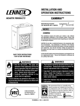
Figure 1
WARNING
The blower must be plugged directly into a properly grounded
three-prong receptacle, 120 VAC, 60 Hz, single phase. Do not
cut or remove the grounding prong from this plug.
Installation must be in accordance with National Electrical
Code, ANSI/NFPA 70 - latest edition. In Canada, the current
CSA C22.1 Canadian Electrical Code - latest edition.
GENERAL INFORMATION
These blower kits can easily be installed when the fireplace has a pre-
installed junction box. You just have to plug them in.
If you encounter any problems, need clarification of these instructions or
are not qualified to properly install this kit, contact your local distributor
or dealer.
Read this instruction sheet in its entirety before beginning the installation.
ALL WARNINGS AND PRECAUTIONS IN THE INSTALLATION AND
OPERATION MANUAL PROVIDED WITH THE APPLIANCE APPLY TO
THESE INSTRUCTIONS.
SHUT DOWN THE APPLIANCE AND ALLOW IT TO COMPLETELY COOL
BEFORE PROCEEDING.
The blowers have magnetic blower mounts. The junction box (factory
installed on approved fireplaces for the use of this blower kit) must be
connected to 120 VAC service before permanently enclosing the fireplace.
Blower
with Magnet
Blower
with Magnet
Rating: 120 volt, 60HZ , .63A
Thermodisc, Automatic
Thermal Fan Activator
Connector for
Optional Rheostat
Electrical Connection
with Ground Connection
NOTE: DIAGRAMS & ILLUSTRATIONS ARE NOT TO SCALE.
Printed in U.S.A. © 2000 Innovative Hearth Products
P/N F49 Rev. H 02/2017
IHP reserves the right to make changes at any time, without notice, in design, materials, specifications, prices and also to discontinue colors, styles and products. Consult your local distributor for
fireplace code information.
IHP
1508 Elm Hill Pike, Suite 108 • Nashville, TN 37210

2
Figure 1
Ventilateur et
aimant
Ventilateur et
aimant
Spécifications : 120 volts, 60HZ , .63A
Thermodisque, Activateur
Thermique de ventilateur
Connecteur pour
gradateur optionnel
Prise de courant a
trois branches
REMARQUE : LES SCHÉMAS ET LES ILLUSTRATIONS NE SONT PAS À L’ÉCHELLE
ASSEMBLAGE DU VENTILATEURS
UZY5 / PUZY5
P/N F49
Rév. H, 02/2017
KITS ET ACCESSOIRES DE
FOYER
INCLUS DANS LE KIT
2 - Assemblage du ventilateur
1 - Feuillet d’instructions
OUTILS NÉCESSAIRES
Robertson (carré) ou Philips (étoile)
INSTRUCTIONS D’INSTALLATION D’UN ENSEMBLE DE VENTILATEUR
S’APPLIQUANT AUX LES FOYERS FIGURANT AU TABLEAU 1
L’ouverture d’accès pour brancher le 120VAC est localisée dans le coin
inférieur arrière du côté droit extérieur du foyer.
ATTENTION : Lorsque l’ensemble de ventilateurs nécessite un entretien,
l’alimentation électrique doit être coupée.
Ces ventilateurs ne requièrent pas d’entretien régulier; cependant,
un nettoyage périodique s’avère nécessaire. Vérifier l’espace
sous l’âtre du foyer, ainsi qu’à l’avant des ventilateurs et nettoyer
avec un chiffon ou aspirateur au moins une fois par mois durant
la saison d’utilisation.
DIRECTIVES D’INSTALLATION
Étape
1. Ouvrez le volet inférieur du foyer ou retirez la façade avant, selon
le cas.
Étape
2. Si vous remplacez un kit existant, retirez d’abord l’ancien kit. Dans
certains foyers, cela peut nécessiter l’enlèvement de la jauge de
dérivation catalytique (tirez-le vers le haut et hors du support) et
les vis de montage.
Étape
3. Installez les ventilateurs dans le centre du dos du foyer.
Étape
4. Pour les foyers avec un interrupteur de ventilateur thermodisque
préexistant, le commutateur dans le kit peut être jeté et les con-
necteurs attachés au commutateur existant. Pour tous les autres,
installez le montage magnétique thermodisque sous la chambre
de combustion vers le côté droit.
Étape
5. S’il est équipé d’une jauge de dérivation catalytique, réinstallez-le.
AVERTISSEMENT
Le ventilateur doit être branché directement dans une prise
monophasée à trois branches 120 VCA – 60 Hz correctement
mise à la terre. Ne pas retirer ou couper la branche de mise à
la terre de la prise.
L’installation doit être conforme à la version la plus récente du
National Electrical Code, ANSI/NFPA 70. (Au Canada, se reporter
à l’édition la plus récente du Code canadien de l’électricité,
CSA C22.1).
INFORMATIONS GÉNÉRALES
Ces ensembles de ventilateurs s’installent facilement lorsque le foyer est
muni d’une boîte de jonction électrique, laquelle sert au branchement des
ventilateurs.
Si vous avez un problème quelconque, avez besoin de clarification pour
ces instructions ou n’êtes pas qualifié pour installer correctement ce ven-
tilateur, contactez votre distributeur ou détaillant local.
Lisez toute les instructions sur cette feuille avant de commencer l’installation.
LES MISES EN GARDE ET AVERTISSEMENTS DONNÉS DANS LE MANUEL
D’INSTALLATION ET D’UTILISATION S’APPLIQUENT AUSSI POUR LE
PRÉSENT FEUILLET D’INSTALLATION.
ÉTEINDRE LE FOYER ET LE LAISSER REFROIDIR COMPLÈTEMENT AVANT
DE FAIRE LES RÉGLAGES.
Les ventilateurs comportent des montures magnétiques. La boîte de
jonction (installée en usine sur les foyers certifiés avec cet ensemble
de ventilateurs) doit être branchée au service 110VAC avant que le foyer
ne soit encastré de façon permanente.
Assemblage du ventilateurs
Nº cat. Modéle Description
UZY5 UZY5
UZY5/PUZY5 Ventilateur - BrentwoodMC SP, Villa VistaMC,
MontecitoMC, WCT4820WS, WCT6820WS, WRT4826WH,
BISMD Ultima-1, BIS Panorama, et BIS Tradition CE,
Montecito EstateMC, WCT6840WS, Montecito Estate CAT,
WCT6940WS et BIS Tradition
Tableau 1
Imprimé aux États-Unis © 2000 Innovative Hearth Products
P/N F49 Rév. H 02/2017
IHP se réserve à tout moment le droit d’apporter sans préavis des changements à la conception, aux matériaux, aux carac-téristiques ou aux prix, ainsi que de supprimer des optionsde couleurs, de
styles et de produits. Pour obtenir de l’information sur les codes des foyers, contacter le distributeur de votre région
IHP
1508 Elm Hill Pike, Suite 108 • Nashville, TN 37210
/