Page is loading ...

PV700a / PV1000a pellet burners
p 1/ 59
DK9401B1 www.pelltech.eu
PV700a/PV1000a pellet burners
User manual
DK9401B1

PV700a / PV1000a pellet burners
p 2/ 59
DK9401B1 www.pelltech.eu
Contents
Safety precautions ......................................................................................................................................... 4
Warnings ....................................................................................................................................................... 4
Notice ............................................................................................................................................................ 4
Set of components ........................................................................................................................................ 7
1 General description ............................................................................................................................... 8
1.1 Safety devices .............................................................................................................................. 12
1.2 Pellets .......................................................................................................................................... 13
2 Installation ........................................................................................................................................... 13
2.1 Prerequisites to boiler and boiler room ...................................................................................... 13
2.2 Burner installation ....................................................................................................................... 15
2.3 Water sprinkler ............................................................................................................................ 24
2.4 External auger ............................................................................................................................. 24
2.5 Pellet storage ............................................................................................................................... 25
2.6 Electrical connections .................................................................................................................. 25
2.7 Initial start-up .............................................................................................................................. 27
3 Optional components .......................................................................................................................... 27
3.1 GSM modem ................................................................................................................................ 27
3.2 Error output ................................................................................................................................. 28
3.3 Flue gas fan .................................................................................................................................. 29
3.4 Oxygen amount sensor ................................................................................................................ 30
3.5 Ash removal system .................................................................................................................... 31
3.6 External boiler temperature sensor ............................................................................................ 31
4 Operation and service ......................................................................................................................... 32
4.1 User interface .............................................................................................................................. 32
4.2 Starting and stopping .................................................................................................................. 33
4.3 Fuel refilling ................................................................................................................................. 33
4.4 Statuses and parameters ............................................................................................................. 33
4.5 Output power levels .................................................................................................................... 40
4.6 Main menu and settings .............................................................................................................. 40

PV700a / PV1000a pellet burners
p 3/ 59
DK9401B1 www.pelltech.eu
4.7 Regular maintenance .................................................................................................................. 43
5 Problems and solutions ....................................................................................................................... 43
6 Burner status change logic .................................................................................................................. 45
7 Annex 1 Electrical diagrams ................................................................................................................ 47
8 Annex 2 – Controller board ................................................................................................................. 50
9 Annex 3 Control unit ........................................................................................................................... 53
10 Annex 4 Table of parameters .......................................................................................................... 55
11 Annex 5 Table of languages ............................................................................................................. 57
Warranty ..................................................................................................................................................... 58

PV700a / PV1000a pellet burners
p 4/ 59
DK9401B1 www.pelltech.eu
Safety precautions
Do not start the burner before it is connected to the boiler and the boiler is connected to the
chimney.
It is recommended to wear a respirator while handling pellets.
The boiler room where the burner is installed must fulfil all rules and recommendations given by
authorities.
All electrical connections must be done by trained professionals.
No flammable materials must be stored near the burner.
Warnings
Changing the construction of the burner without written permission from the manufacturer is
forbidden.
Use only spare parts provided or approved by the manufacturer in order to avoid any damage to
the burner and dangers resulting from it.
Welding is allowed only after disconnecting the burner from electric supply. The circuit board
must be removed from the burner.
Do not open any boiler door while the burner is in operation.
Notice
Manufacturer of burners has right to make changes in construction of burner and its firmware.
Burner corresponds to following directives and standards:
Directive 2004/108/EC
Directive 2006/95/EC
Directive 2001/95/EC
Directive 2006/42/EC
EN 15270 2008
EN 230 2005
EN 60370-2-5 2002

PV700a / PV1000a pellet burners
p 5/ 59
DK9401B1 www.pelltech.eu
Pellet burner PV 700a
No
Year of production
2014
Electrical supply
230V
Max heat input
20kW
Emission class
5
Noice emission
52dB
Power consumption at stand-by
7 W
Manufacturer: Pelltech OÜ, Sära tee 3, Peetri, Estonia
Pellet burner PV 1000a
No
Year of production
2014
Electrical supply
230V
Max heat input
1000kw
WW
Emission class
5
Noice emission
52dB
Power consumption at stand-by
7 W
Manufacturer: Pelltech OÜ, Sära tee 3, Peetri, Estonia

PV700a / PV1000a pellet burners
p 6/ 59
DK9401B1 www.pelltech.eu

PV700a / PV1000a pellet burners
p 7/ 59
DK9401B1 www.pelltech.eu
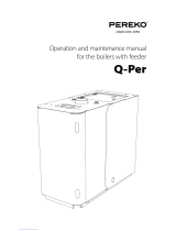
Set of components
1. Burner with burning chamber
2. Bracket 2 pcs
3. Hose 76mm
3
1
2

PV700a / PV1000a pellet burners
p 8/ 59
DK9401B1 www.pelltech.eu
1 General description
PV700a and PV1000a are burners of wooden pellets (sawdust granules) that are intended to use in
different boiler houses. Only wooden pellets with 6 or 8mm diameter can be used to run burners. You
cannot use any other form of fuel but pellets to run the burner. Unique design of burners’ burning
chambers allows to burn also industrial pellets. The construction of the burners allows them to be used
with different boilers: liquid fuel, solid fuel and universal boilers. The burner is connected to the boiler
by using a connection plate.
The burner is equipped with a safety thermostat, a melting hose, temperature sensor, sprinkler system
with pressure switch and auxiliary battery for protection against back-burning. Main technical data are
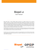
given in Table 1 and Figure 1.
Parameter
Unit
PV700a
PV1000a
L total length
mm
1190
1306
L1 housing length
mm
592
624
L2 burning chamber length
mm
590
682
⌀D1feeder auger’s tube diameter
mm
80
80
Pellet inlet tube diameter
mm
76
76
H total height
mm
598
621
H1 burning chamber height
mm
451
545
W burner housing width
mm
606
706
W1 burning chamber width
mm
528
614
Required chimney diameter
mm
300
350
Mass net/bruto
kg
150/185
230/280
Max amount of flue gases
M3/h
1800
2500
Max fuel consumption
kg/h
150
213
Maximum/nominal power
kW
700
1000
Minimum power
kW
200
250
Hold flame power
kW
40
60
Noise level
dB
58
58
Emission class EN 15279
-
5
5
Operating temperature
Co
-10…40
-10…40
Supply voltage
VAC
3x380
3x380
El power at ignition
W
1100
2100
El power, average
W
370
480
El power at standby
W
20
20
Main components of the burner and their locations are depicted in Figure 2 and described in Table 2 .
Table 1 Technical data of burner

PV700a / PV1000a pellet burners
p 9/ 59
DK9401B1 www.pelltech.eu
Figure 1 Main measurements of PV1000 burner

PV700a / PV1000a pellet burners
p 10/ 59
DK9401B1 www.pelltech.eu
14
15
13
5
15
1
2
3
4
5
6
7
16
17
5
18
20
7
12
11
10
9
8
19
21
Figure 2 Main components

PV700a / PV1000a pellet burners
p 11/ 59
DK9401B1 www.pelltech.eu
No
Name
Description
1
Burning
chamber
The part of the burner that is inside the boiler and where pellets are burnt.
2
Burner body
The part of the burner that is outside the boiler and where burner’s control and
pellets supply takes place.
3
User interface
Control board with screen, navigation buttons and indication lights.
4
Control unit
Electrical- and control panel what contains inverters, fuses, relays, main
controller board and other control devices
5
Water sprinkler
Sprinkler system will spray water to extinguish the fire in feeder’s tube in case
of back burning. The sprinkler system is activated only when the temperature
of feeder auger rises dangerously high.
6
Grate cleaning
motor
Linear motor moves the grates in burning chamber and pushes ash out from
burning chamber. This cleaning cycle is made periodically. The interval between
cleaning cycles can be controlled by PAR48. In each cleaning cycle, the linear
motor pulls grates back then pushes the grates completely out. The linear
motor has 75mm stroke and end switches for stop. Linear motor current limit
can be set by PAR47. Linear motor is protected by fuse F10 what is installed on
the controller board (board version BBB v2.1).
7
Igniter
Igniter´s purpose is to ignite loaded fuel making the burning process start.
Igniter is installed on the burner together with igniter holding pipe. PV700 has
2 igniters and PV1000 4 igniters.
8
Brick
temperature
sensor
A sensor to adjust bricks’ heat up speed according to temperature rise. Brick
temperature rise speed control helps to reduce thermal stress of bricks and
prolong their lifetime.
9
Cleaning hatch
Hatch below burning chamber to ease the removal of ash under the grates.
10
Grates support
frame
Holds moving and stationary grates in correct position.
11
Grates
Burning of pellets takes place on the cast iron grates. Air needed for burning is
blown to burning chamber via holes with different size. Burner has moving and
fixated grates. Moving grates move periodically to clean the burning chamber.
12
Fire bricks
Burning chamber is surrounded with heat resistant from up and sides. Bricks
are necessary for proper airflow and combustion.
13
Flame sensor
Photocell´s purpose is to recognize flame in the burning chamber.
14
Level sensor
Optical fuel level sensors recognize the fuel level in the vertical pipe. Fuel is
recognized when pellets pass the optical beam between sensors.
15
Combustion air
fans
Left – primary
Right –
Primary fan blows main burning air needed for ignition, burning and
gasification of the fuel.
Secondary fan blows air through burning chamber back-wall and holds burning
Table 2 List of main components

PV700a / PV1000a pellet burners
p 12/ 59
DK9401B1 www.pelltech.eu
secondary fan
quality and optimal flue gas content. To control the burning procedure oxygen
sensor (optional) for fan’s speed regulation is used.
Both fans rotation speed is measured by sensor, installed near the impeller
axle. The sensor is reading magnetic field changes caused by magnet installed
on the impeller axle.
16
Controller board
Controller board controls the burner´s burning process, by calculating fuel
amount also feeder and auger work during burning process. Depending on the
input signals from the sensors, controller makes necessary changes to the
output states to maximize burning efficiency. Controller has a single control
board.
17
GSM modem
(optional)
A GSM modem enables burner to send SMS messages with various information
of burner´s operating states (errors). GSM modem is located on control unit.
18
Feeder auger
motors
Internal feeders are used to deliver correct amount of fuel into burning
chamber. Delivered fuel amount is regulated by periodical work of feeder gear
motors.
24V DC motors are supplied from backup battery to empty feeder tubes in case
of power failure.
19
Battery
When there is no power from the main power supply then the burner is
operating on battery power. PV1000 uses two 12V 3,4 Ah batteries. Because
the battery is a safety element, the burner checks batteries condition and does
not start the next working cycle if the batteries voltage is too low.
20
Internal feeder
screw
Hollow spiral connected to feeder motor to transport pellets into burning
chamber. Screw is not tightened to motor, but has small slack. It lowers the
mechanical stress and expands gear motor lifetime.
21
Pressure sensor
connection
Metal tube to connect pressure sensor input. Pressure sensor measures
draught in burning chamber and enables the controller to regulate flue gas fan
speed.
1.1 Safety devices
The back-burning is the biggest danger risk at burners working procedure. Back-burning appears when
usual pressure or draught conditions have changed in boiler’s combustion chamber. There are several
reasons for such changes.
In order to secure operational and fire safety the PV700a/PV1000a burners are equipped with following
safety devices:
Back up batteries. Enable to finish safely burning procedure in normal conditions or during
unexpected black out in mains supply.
Melting hose. The external auger is connected to the burner with a special hose (∅ 76mm), which is
made from easily melting polyurethane material that interrupts when back-burning takes place.
Such measurement avoids entrance of the flame from burner into external auger and pellets
container.
Thermostatic sprinkler valve. Enables to extinguish the fire in feeder’s augers tube by spraying
water into it, when burner is overheated due to possible back-burning or any other reason.

PV700a / PV1000a pellet burners
p 13/ 59
DK9401B1 www.pelltech.eu
Fire safety water pressure control switch (pressostat). Enables to keep necessary water pressure in
water reservoir and to ensure with that successful extinguishing procedure when needed.
Pressostat switch allows starting the burner only if water supply is present and pressure exists.
1.2 Pellets
Wooden pellets or saw dust granules are concentrated and homogenized wooden fuel. Pellets are
pressed with high temperature. No extra materials are added, pellets are held together by a natural
ingredient found in wood – lignin. Pellets are neutral, renewable fuel. Its burning doesn’t spoil CO2
balance in the atmosphere. Not only premium but also the industrial pellets can be used in
PV700/1000a. Pellets must be stored in a dry and ventilated room. Table 3 provides an overview of pellet
properties and threshold values.
Premium pellets
Industrial pellets
Raw material
Sawdust, cutter shavings, stem
wood
Forest, plantation and other
virgin wood, chemically
untreated wood residues
Calorific value
4700-5100 kWh/ton
ca 4700 kWh/ton
Volume weight
ca 650-670 kg/m3
>675 kg/ m3
Volume of 1 ton pellets
1.5-1.6 m3
ca 1.5 m3
Diameter
6-10 mm
6-12 mm
Length
3-5 x diameter
ca 4mm
Moisture content
8-10 %
ca 5 %
Ash content
ca 0,5%
ca 2%
To replace 1000 l light oil
ca 2 tons or 3 m3
ca 2 tons or 3 m3
2 Installation
2.1 Prerequisites to boiler and boiler room
In order to install the burner, the boiler must meet to the following requirements:
It is recommended to use three pass boilers.
The construction of the boiler must make it possible to open the door of the boiler with the burner
connected and removing ash from the furnace. If the door of the boiler is too narrow for opening it
with the burner, then extra hinges must be mounted.
If there is not sufficient (less than 5Pa) negative pressure in the furnace, a flue gas fan should be
installed to improve the movement of the exhaust gases.
The boiler must be installed into boiler’s room in a way that there is enough space for cleaning the
burner, the boiler, the smoke pipe and removing the ash.
The burning chamber must not touch the bottom of the boilers furnace (min 10 cm distance needed).
Table 3 Pellets’ overview

PV700a / PV1000a pellet burners
p 14/ 59
DK9401B1 www.pelltech.eu
The boiler room where the burner is installed must fulfill all rules and recommendations given by
local authorities.
Boiler room must provide constant air supply of 1500 m³ per hour (ca. 1600 cm2 air inlet opening).
In order to mount the burner to the boiler door, it must have mounting holes. See Figure 3 .
Notice! If the burner is installed to the boiler, the door’s or the installation flange´s thickness should be
8-14mm.
Cutting contour of hole to be cut to boilers door in order to install PV1000 burner.
Dimension
Unit
Value
⌀D hole for burning chamber neck
mm
400
⌀D1 flange bolt ring diameter
mm
490
⌀D2 bolt holes
mm
6 x 13
Bolt hole offset angle
deg
30
Angle between bolt holes
deg
60
Figure 3 Boiler door mounting opening
Figure 4 Contour of cutting

PV700a / PV1000a pellet burners
p 15/ 59
DK9401B1 www.pelltech.eu
Pellet burners need regular cleaning and therefore boiler construction must allow easy opening of
boiler’s door without removing the burner. The minimum size of opening in boiler’s door depends on the
position of door hinges. Figure 6 below illustrates the situation. Point C is the critical point.
In order to keep door width minimum and boiler’s door opening small, a double hinge solution
can be used. As double hinges add another degree of moving-freedom, door must be fastened on both
sides. Slide-out doors with guide rails is also an option.
2.2 Burner installation
Burners are delivered to customer in fully put together. Before mounting the burner to boiler it has to be
disassembled i.e. bricks have to be removed and burning chamber separated from burner and air box.
Mount the burning chamber on the
inner side of the boiler door.
Double hinges
Boiler’s firebox depth L must be at least 2,5
times longer than the length of burner’s
burning chamber. Thus minimal length of
the firebox L for PV700 has to be 1500 mm
and for PV1000 1800mm. The height of
firebox must leave at least 100 mm space
(H1) for ash below burning chamber.
Minimum dimensions: L1 ≥700mm; H
≥650mm. See Figure 5.
Figure 5 Firebox depth
Figure 6 Burner has to
reach off from boiler
Figure 7

PV700a / PV1000a pellet burners
p 16/ 59
DK9401B1 www.pelltech.eu
Figure 8
Install the insulation rope between
the burning chamber and the boiler
door. The rope must be installed
near the outer perimeter of the
burning chambers back wall.
Figure 9
Use 6 M12x60mm bolts, spacers
and distance nuts respective to
the bolts.

PV700a / PV1000a pellet burners
p 17/ 59
DK9401B1 www.pelltech.eu
Connect the static grate holders with
the side stone holders separately and
install them together into the burning
chamber as a frame. Fix them with
M8x16mm bolts to the burning
chamber.
Figure 10
Figure 11
Grate holders installation
Install the burning chambers
bottom panel (15x15mm
insulation rope must be inserted
to the slot in the panel) with 6
M8x16mm bolts.
Install the burning chambers
front panel (heat shield), use
M8x16mm bolts.

PV700a / PV1000a pellet burners
p 18/ 59
DK9401B1 www.pelltech.eu
Connect the moving grate holders
with M6x12mm bolts.
Figure 12
Figure 13
Install the burning chamber’s front
brick holders, use M8x16mm bolts.

PV700a / PV1000a pellet burners
p 19/ 59
DK9401B1 www.pelltech.eu
Release the igniter tube screws and
while inside the holders pull the tubes
out about half of the total length.
Move the air separator to its correct
position (according to the boiler door
thickness) and fix it with screws.
Figure 14
Figure 15

PV700a / PV1000a pellet burners
p 20/ 59
DK9401B1 www.pelltech.eu
Install the ceramic sealing strips on
the boiler door. Fix them temporarily
in position with any ordinary
cellophane tape (scotch).
Cut away the excessive sealing on the
perimeter of the air chamber.
Mount the burner’s housing on the
boiler door, using 4 M12x70mm bolts
and respective washers.
Push the igniter tubes through the
burning chambers back wall and fix
them in position with M4 screws.
Figure 18
Figure 17
Figure 16
/