Page is loading ...

EVALUATION BOARD MANUAL
FOR RADIO MODULES
EV Order Code Module order code Marketing Name
2613029237001 2613021137000 Elara-II
VERSION 1.2
JUNE 9, 2020


Abbreviations and abstract
Abbreviation Name Description
BDS BeiDou navigation
System Chinese satellite navigation system
COM Communication
CTS Clear to send
ESD Electro Static
Discharge
FSE Field Sales Engineer Your personal sales and support contact person
FTDI Future Technology
Devices International
Galileo European satellite navigation system
GLONASS Global Navigation
Satellite System Russian satellite navigation system
GNSS Global Navigation
Satellite System
GPS Global Positioning
System American satellite navigation system
HIGH High signal level
IO Input Output
LDO Low-dropout Linear voltage regulator
LED Light Emitting Diode
LOW Low signal level
PC Personal Computer
RC Resistor Capacitor
RF Radio frequency Describes everything relating to the wireless
transmission.
RTS Request to send
RST Reset
SWDCLK Serial Wire Debug
Clock
UART
Universal
Asynchronous
Receiver Transmitter
Universal Asynchronous Receiver Transmitter allows
communicating with the module of a specific
interface.
USB Universal Serial Bus
VCC Supply voltage
Evaluation board manual version 1.2 © June 2020
www.we-online.com/wireless-connectivity 2

Contents
1 Supported radio modules 5
2 Functional description 6
2.1 Takingintooperation............................... 6
3 Development board 8
3.1 Blockdiagram................................... 8
3.2 Jumpers...................................... 9
3.3 Connectors .................................... 11
3.3.1 CON1 .................................. 12
3.3.2 CON2 .................................. 12
3.3.3 CON4 .................................. 12
3.4 SwitchesandButtons .............................. 13
3.4.1 RESET GNSS button . . . . . . . . . . . . . . . . . . . . . . . . . . 14
3.4.2 ON/OFF GNSS button . . . . . . . . . . . . . . . . . . . . . . . . . 14
3.5 Functionblocks.................................. 14
3.5.1 Powersupply .............................. 14
3.5.1.1 Bus powered, power supply through USB . . . . . . . . . . . . 14
3.5.1.2 Battery powered, power supply through AAA Battery . . . . . . 14
3.5.2 JP1 - Current measurement . . . . . . . . . . . . . . . . . . . . . . 15
3.5.3 JP2 - UART Communication Interface Selection . . . . . . . . . . . 15
3.5.4 JP3 - Communication Interface . . . . . . . . . . . . . . . . . . . . 15
3.5.5 JP4 - Antenna Selection . . . . . . . . . . . . . . . . . . . . . . . . 15
3.5.6 JP5 - Active Antenna Bias . . . . . . . . . . . . . . . . . . . . . . . 15
3.5.7 JP6 - CTS/RTS Pull Resistors . . . . . . . . . . . . . . . . . . . . . 15
3.5.8 JP7.................................... 15
3.5.9 JP8 - Power Supply selection . . . . . . . . . . . . . . . . . . . . . 16
3.5.10UART/USB............................... 16
3.5.11LED ................................... 16
3.5.11.1 STATUS GNSS LED . . . . . . . . . . . . . . . . . . . . . . . . 16
3.5.11.2 1PPSGNSSLED.......................... 16
3.5.11.3 TXGNSSLED ........................... 16
3.5.12 Proprietary RF Block . . . . . . . . . . . . . . . . . . . . . . . . . . 17
3.6 AssemblyInformation .............................. 17
3.6.1 Soldering Recommendation . . . . . . . . . . . . . . . . . . . . . . 17
3.6.2 Lightsensitivity ............................. 17
3.7 Schematic..................................... 18
3.8 Layout....................................... 21
4 Regulatory compliance information 23
4.1 Exemptionclause................................. 23
5 Important notes 24
5.1 General customer responsibility . . . . . . . . . . . . . . . . . . . . . . . . . 24
5.2 Customer responsibility related to specific, in particular safety-relevant ap-
plications ..................................... 24
5.3 Best care and attention . . . . . . . . . . . . . . . . . . . . . . . . . . . . . 24
Evaluation board manual version 1.2 © June 2020
www.we-online.com/wireless-connectivity 3

5.4 Customer support for product specifications . . . . . . . . . . . . . . . . . . 24
5.5 Productimprovements.............................. 25
5.6 Productlifecycle ................................. 25
5.7 Propertyrights .................................. 25
5.8 General terms and conditions . . . . . . . . . . . . . . . . . . . . . . . . . . 25
6 Legal notice 26
6.1 Exclusionofliability................................ 26
6.2 Suitability in customer applications . . . . . . . . . . . . . . . . . . . . . . . 26
6.3 Trademarks .................................... 26
6.4 Usagerestriction ................................. 26
7 License terms 28
7.1 Limitedlicense .................................. 28
7.2 Usageandobligations .............................. 28
7.3 Ownership..................................... 29
7.4 Firmwareupdate(s)................................ 29
7.5 Disclaimerofwarranty .............................. 29
7.6 Limitationofliability................................ 30
7.7 Applicable law and jurisdiction . . . . . . . . . . . . . . . . . . . . . . . . . . 30
7.8 Severabilityclause ................................ 30
7.9 Miscellaneous................................... 30
Evaluation board manual version 1.2 © June 2020
www.we-online.com/wireless-connectivity 4

1 Supported radio modules
The evaluation board is exclusively for the Elara-II module:
Order code Product Name Description
2613021137000 Elara-II GNSS module supporting GPS and
GLONASS navigation systems
Order code Description
2613029237001 Elara-II module EV-Kit
Table 1: Compatibility
Figure 1: Product image
Kit Content 2613029237001 Quantity
Evaluation board with Elara-II 1
USB2 A to USB Micro cable 1
External active antenna 1
Packaging: Cardboard Box, ESD bag 1
Table 2: Content Elara-II module EV-Kit
Evaluation board manual version 1.2 © June 2020
www.we-online.com/wireless-connectivity 5

2 Functional description
The evaluation board offers the user the possibility to put the compatible GNSS module into
operation and to evaluate its features. Furthermore, it represents our reference design for
the integration of the compatible GNSS module in an application board.
The evaluation board can be connected to an USB port of a PC. For the connection to a
microcontroller system the development board is equipped with a multi-pin connector which
gives access to all necessary pins of the GNSS module. Jumpers allow the module to be
disconnected from components such as the USB interface which are not required.
2.1 Taking into operation
Before starting to work with the evaluation board make sure that:
• The jumpers on the EV board are placed on the default locations.
• FTDI driver package is installed on the PC. The latest version of the drivers can
be downloaded from (www.ftdichip.com/Drivers/VCP.htm). Please use the setup ex-
ecutable package or follow the install instructions from FTDI.
• Evaluation board is connected to the PC via USB-cable provided in the evaluation kit.
• Module power supply (VCC) is stable and able to reliably supply the module’s static
and peak current consumption as specified by the module manual.
• COM port is detected and installed on the PC. The (COM) port name of the evaluation
board can be found using the device manager on Windows and the display message
(dmesg) on Linux. For example, the evaluation board might appear similar to "COM12"
on windows and "/dev/ttyUSB0" on Linux. Once the COM port is detected, USB initial-
isation is completed.
• Push the ON/OFF GNSS Button to switch the module from hibernate to full power state.
Please make sure to do this only after the USB initialisation. Pressing the ON/OFF
GNSS Button before USB initialisation, can cause the PC Device Manager to interpret
the GNSS module as Microsoft serial ballpoint mouse. In such event, disconnect the
board from the PC and repeat the steps.
• WENSS PC-tool can be used to take the evaluation board into operation and communi-
cate with the module. Once connection to the evaluation board is properly estabilshed,
flow of messages from the GNSS module should be visible in the PC-tool. Please refer
to the PC-Tool manual for detailed information.
Please refer to the module reference manual to get the detailed module specific information.
Evaluation board manual version 1.2 © June 2020
www.we-online.com/wireless-connectivity 6


3 Development board
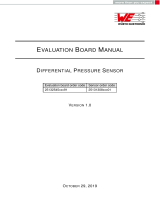
3.1 Block diagram
USBUSB
Voltage
regulator
Voltage
regulator
FTDI USB
converter chip
FTDI USB
converter chip Elara-II module
ConnectorsConnectors ButtonsButtons
JumperJumper
Evaluation board
Internal
Patch
Antenna
Internal
Patch
Antenna
LEDsLEDs
Proprietary RF
module*
SMA
Connector
SMA
Connector
*Planned for future Hardware Version
Battery
holder*
Battery
holder*
Figure 3: Block diagram
Evaluation board manual version 1.2 © June 2020
www.we-online.com/wireless-connectivity 8


JP1 Function Jumper set (default)
1,2 No connection No
3,4 Power bridge (remove for current measurement) Yes
JP2 Function Jumper set (default)
1,3 UART to USB communication Yes
3,4 UART to proprietary RF communication No
JP3 Function Jumper set (default)
1,2 RX UART interface to TX-GNSS module Yes
3,4 TX UART interface to RX-GNSS module Yes
5,6 CTS UART interface to RTS-GNSS module No
7,8 RTS UART interface to CTS-GNSS module No
9,10 RST-control UART interface to RST-GNSS module No
11,12 Ground connection No
JP4 Function Jumper set (default)
2,4 Active antenna No
3,4 Passive antenna Yes
JP5 Function Jumper set (default)
1,2 Active antenna bias Yes
3,4 No connection No
JP6 Function Jumper set (default)
1,2 CTS pullup Yes
3,4 RTS pulldown No
JP7 Function Jumper set (default)
1,2 Mode set (reserved for future use) No
3,4 Busy LED (reserved for future use) No
Evaluation board manual version 1.2 © June 2020
www.we-online.com/wireless-connectivity 10

3.3 Connectors
Figure 5: Connectors
Connector Function
CON1 Micro-USB connector for host connection and VCC bus supply
CON2 SMA connector for external active antenna
CON4 UART interface Thyone-I module (reserved for future use)
Evaluation board manual version 1.2 © June 2020
www.we-online.com/wireless-connectivity 11

3.3.1 CON1
Connector CON1 is a micro-USB socket that enables connection to PC via standard micro-
USB cable and also provides supply voltage to the board during USB powered operation.
CON1 Function
Micro-USB connector for host connection and VCC bus supply
3.3.2 CON2
Connector CON2 (SMA Jack) is used to connect an external antenna.
In order use the external active antenna, Jumper JP4 and jumper JP5 has to
be set according to the jumper table
In order use the on-board passive antenna, Jumper JP4 has to be set accord-
ing to jumper table and connector CON2 should be left open
CON2 Function
Inner RF signal
Outer GND
3.3.3 CON4
Connector CON4 is a standard 2.54mm pin header which is used as the UART interface for
the Thyone-I module. This feature is not released in the current evaluation board version
and is subject for a future version.
CON4 Function
1 GND
2 RTS_RF signal
3 Not connected
4 RX_RF signal
5 TX_RF signal
6 CTS_RF signal
Evaluation board manual version 1.2 © June 2020
www.we-online.com/wireless-connectivity 12


3.4.1 RESET GNSS button
Internally the active low reset input of the micro processor is connected via a RC combination
with the power supply to ensure a proper startup of the module. /RESET pin is connected to
this button which provides the possibility for hard reset. Please refer to the module specific
manual for detailed information.
In order to have better signal stability and avoid ESD influence on the module a decou-
pling capacitor of 1nF should be used between Reset pin signal trace of GNSS module and
Ground. This capacitor is not implemented in the evaluation board but recommended for
signal stability and to avoid ESD issues.
3.4.2 ON/OFF GNSS button
The ON/OFF button is connected to the module’s ON_OFF pin. This gives the user the
possibility to switch between the operating modes. Please refer to the module manual for
detailed information.
In order to have better signal stability and avoid ESD influence on the module decoupling
capacitor of 1nF should be used between ON_OFF pin signal trace of GNSS module and
Ground. This capacitor is not implemented in the evaluation board but recommended for
signal stability and to avoid ESD issues.
After switching on and resetting, the module starts in Hibernate mode.
3.5 Function blocks
3.5.1 Power supply
3.5.1.1 Bus powered, power supply through USB
The development board can be powered through the micro USB connector. The integrated
voltage regulator regulates the connected USB voltage of typ. 5V down to 3V and further a
dedicated voltage regulator is used to power the module with the proper voltage supply of
1.8V. If the evaluation board is power sourced the Power LED lights up. USB power supply
can be selected using the jumper JP8. By default the jumper JP8 is set to USB powered
operation.
3.5.1.2 Battery powered, power supply through AAA Battery
The development board also has optional assembly for battery holders on the bottom to con-
nect two AAA batteries. To power up the board using the AAA batteries JP8 should be set
accordingly. (This feature is reserved for future use)
Evaluation board manual version 1.2 © June 2020
www.we-online.com/wireless-connectivity 14

3.5.2 JP1 - Current measurement
By default, JP1 is set to normal operation. If a current meter is connected in place of the
jumper, the power consumption of the radio module can be measured.
If the meter is not attached and the bridge is not set, the module will not receive a supply
voltage. However, the Power LED may be active, as it is connected prior to the current
measurement bridge in order not to distort the module’s power consumption.
3.5.3 JP2 - UART Communication Interface Selection
By default, JP2 is bridged for UART communication through USB interface.
The proprietary RF module provides the possibility to support UART communication through
radio, which can be established by setting the JP2 respectively. (This feature is reserved for
future use)
3.5.4 JP3 - Communication Interface
By default, JP3 is bridged between the TX, RX, CTS, RTS, Reset lines of GNSS module
to UART communication interface. In this setting only TX and RX connections are absolute
necessity for UART communication. CTS, RTS and Reset connections are optional and
provide the possibility to control the relevant module pins using UART interface.
Pins 2, 4, 6 and 8 of the JP3 can also be used to connect GNSS module to any other external
interface instead of bridging the jumper JP3. In such case, beware of IO level compatibility
as these pins have a IO logic level of 1.8V. The host must obey the values stated in the
module’s manual. Especially the IO level restrictions must be implemented by a host system
(i.e. using a level shifter to support the allowed IO levels).
3.5.5 JP4 - Antenna Selection
By default, JP4 is bridged to select the passive patch antenna on the evaluation board, the
jumper setup can be modified according to the jumper table to select the SMA connector for
external active antenna connection.
3.5.6 JP5 - Active Antenna Bias
By default, JP5 is bridged to bias active antenna connected to SMA connector.
3.5.7 JP6 - CTS/RTS Pull Resistors
By default, JP6 is bridged to provide external pullup on CTS of the GNSS module to support
UART communication interface. For detailed information related to the setup of pull resistors
please refer to the module Manual.
3.5.8 JP7
Connections of the jumper JP7 are reserved for future use.
Evaluation board manual version 1.2 © June 2020
www.we-online.com/wireless-connectivity 15

3.5.9 JP8 - Power Supply selection
By default, the jumper JP8 is set to USB powered operation. Other connections of the jumper
JP8 are reserved for future use.
3.5.10 UART / USB
UART interface of the module can be connected to the USB converter by setting the jumper
JP2 and JP3 accordingly. By default, communication takes place through the USB jack.
Using the FTDI-driver the PC tool will show a virtual COM-Port which can be used to com-
municate with the module.
The USB cable length should not exceed 3 meters.
3.5.11 LED
There are three LEDs available on the evaluation board dedicated to indicate the status of
Elara-II module’s functions.
3.5.11.1 STATUS GNSS LED
STATUS GNSS LED is connected to the WAKE_UP pin of the Elara-II module. If the LED is
in steady ON state, it indicates that the module is in full power mode. If the LED is in steady
OFF state, it indicates that the module is in hibernate mode. Please refer to the module
manual for detailed information.
3.5.11.2 1PPS GNSS LED
1PPS GNSS LED is connected to the 1PPS pin of the Elara-II module. 1PPS GNSS LED is
triggered through 1PPS signal pulse once the module obtains 3D position fix. Please refer
to the module manual for detailed information.
3.5.11.3 TX GNSS LED
TX GNSS LED is connected to the TX pin of the Elara-II module. If the LED is in steady
OFF state, it indicates that the module is in hibernate mode. If the LED is in blinking state,
it indicates that the module in full power mode and GNSS messages are transmitted by the
module. Please refer to the module manual for detailed information.
If the RESET_GNSS button on the evaluation board is pressed, the GNSS message trans-
mission is stopped but the TX GNSS LED is in steady ON state, this is because of the pull
up on TX line by the level shifter used in the evaluation board.
Evaluation board manual version 1.2 © June 2020
www.we-online.com/wireless-connectivity 16

3.5.12 Proprietary RF Block
The evaluation board is prepared to use a proprietary RF-Module Thyone-I for UART com-
munication through a radio interface. However, this feature is not released in the current
evaluation board version and is subject for a future version.
3.6 Assembly Information
3.6.1 Soldering Recommendation
For proper assembly of module on the host PCB, the recommended soldering parameters
given below shall be followed.
Solder stencil thickness: max. 100 µm
Solder stencil opening: 80 % to 100 %
Solder stencil type: Electroformed or Laser cut stencil
Solder paste type: Type 4.5 to Type 6
Peak reflow temperature: 245°C
3.6.2 Light sensitivity
Elara-II module is sensitive to light. Exposure to light might result in malfunction. For proper
functionality of the module an enclosure against light shall be used. On the evaluation board
the module is covered by a silicone encapsulating compound.
Evaluation board manual version 1.2 © June 2020
www.we-online.com/wireless-connectivity 17

3.7 Schematic
261312923xxxx-HW-V2.1
1/3
261312923xxxx-HW-V2.1
17.02.2020 14:03
100nF
TLV1117LV
GND
1µF100nF
GND GND
100nF
GND
n.m.
GND
7427927311
red
56R
GND
GND
GND
GND
GND
100nF
GND
10R10R
10pF
10pF
GND GND
7427927311
7427927311
100nF
GND
100nF
GND
100nF 1µF
GND GND
10R
10R
DFLS130L-7
10R
10R
Micro_USB
GND
TLV1117LV
GND
1µF100nF
GND GND
100nF
GND
n.m.
100pF 4.7µF
GND GND
n.m.
82400152
TS3A27518EPWR
TXB0106PWR
GND
100nF
GND
100nF
GND GND
2x2
GND
GND
GND
100K
GNDGND
50R
50R
0R
red
10kR
GND
GND
ADJ
IN OUT
OUT
IC4
C2C3C4
T1
L2
POWER
R2
AGND
24
GND
4
GND
17
GND
20
TEST
26
CBUS4 9
CBUS3 11
CBUS2 10
CBUS1 21
CBUS0 22
RI# 3
DCD# 7
DSR# 6
DTR# 31
CTS# 8
RTS# 32
RXD 2
TXD 30
VCCIO
1
VCC
19
USBDM
15
USBDP
14
NC
12
RESET#
18
NC
5
OSCI
27
OSCO
28
3V3OUT
16
IC3
FT232RQ
C11
R4
R5
C13
C14
L5
L1
C12
C16
C1 C5
R8
R9
D1
R3
R6
GND 5
ID 4
D+ 3
D- 2
VBUS 1
SHIELD SHELL*4
CON1
ADJ
IN OUT
OUT
IC5
C6C7C8
T2
C9 C10
R23
5
1*2
3*2
2
D3
V+
~EN 20
IN1
IN2
COM1
COM2
COM3
COM4
COM5
COM6
N.C.
GND
NC1
NC2
NC3
NC4
NC5
NC6
NO1
NO2
NO3
NO4
NO5
NO6
IC2
IC1
VCCA
VCCB
OE
A1
A2
A3
A4
A5
A6
GND
B1
B2
B3
B4
B5
B6
C22
C23
C24
1
3
2
4
JP2
1
3
2
4
JP1
2x2
R11
R1
R14
R17
POWER1
R34 1
3
2
4
5
7
9
11 12
10
8
6
JP3
2x6
- +- +
JP8
2x4
1
3
5
7
2
4
6
8
GND GND
3V
3V
3V
3V
D+
D-
5V
5V
VDD_RF
1_8V
1_8V
VCC_GNSS
VCC_GNSS
RST_CTRL
TX_F
RX_F
RTS_F
CTS_F
RX_S
RX_S
CTS_S
CTS_S
RST_CTRL_S
RST_CTRL_S
TX_S
TX_S
RTS_S
RTS_S
TX_RF
RX_RF
RTS_RF
CTS_RF
B6_RF
TX_GNSS
RX_GNSS
/RTS_GNSS
/CTS_GNSS
/RST_GNSS
BOOT_RF
SWDCLK_RF
VBUS
VDD_3V
VDD_3V
VDD_3V
VDD_3V
VDD_3V
ELARA-II EV Board
HW-V1.0
ArKr
USB
VDD
I/O1
GND
I/O2
DESCRIPTION DATE NAME
TITLE:
PROJECT:
SHEET
DRAWN
DATE NAME REV:
CHECK
APPVD
FILE NAME:
VERTRAULICH/CONFIDENTIAL
BAT_1BAT_2
USB-Interface
Power-supply 3V
Power-supply-1.8V
JP2:
JP=3-1 IN=1 -> COM<->NO (USB)
JP=3-4 IN=0 -> COM<->NC (Thyone Module)
UART Jumper/ I2C Interface
JP8:
1:3V Battery <-> 3: VDD_RF
RF Current Measurement (Battery supply)
2: NC
3: VDD_RF <-> 4:3V
RF Current Measurement
(3V Supply)
5: BOOT_RF <-> 6:GND
7: SWCLK_RF <-> 8:Pulldown
CON1: Micro-USB
3V
1.8V
JP1:
1:NC 2:NC
3:I_IN_GNSS<->4: VCC_GNSS
GNSS Current Messurement
1.8V_LOGIC
1.8V_LOGIC
GNSS Module Decaps.
Thyone-I Module Decaps.
Power-supply
<-
->
-> ->
->
->
<-<-
->
<-
<-
<-
3V to 1.8V
Level Shift
NCNC
Figure 7: Schematic sheet-1
Evaluation board manual version 1.2 © June 2020
www.we-online.com/wireless-connectivity 18

261312923xxxx-HW-V2.1
2/3
261312923xxxx-HW-V2.1
12.11.2019 14:41
GND
GND
2k2R
blue
yellow
2k2R
GND
GND
GND
GND
n.m.
n.m.
22pF
GND
n.m.
2k2R
GND
yellow
GND
430152043826
430152043826
2x2
BSS138
100k GND
GND
10K
100PF
GND
2k2R
BSS138
100k GND
GND
10K
100PF
GND
1kR
greenyellow
n.m.
BSS138
100k GND
GND
10K
100PF
GND
2k2R
blue
R12
LED_BUSY
LED_1
R13
C26
C27
C28
RF
2
GND
3
SWDCLK
4
SWDIO
5
RESET
6
BOOT
7
NFC2
B2
VDD
8
NFC1
B1
LED_1 11
LED_2 12
UTXD 13
URXD 14
RTS 15
CTS 16
WAKE_UP 17
GND 18
ANT_PAD
1
RSVD_4
B5
RSVD_1
B3 RSVD_2
B4 RSVD_3
B6 OP_MODE
9
BUSY
10
THYONE-I
R7
LED_2
O1 O2 O3
4
3
2
1
S2
4
3
2
1
S1
1
3
2
4
JP7
S
G
D
T6
R33
R36
C42
R37
S
G
D
T5
R38
R41
C45
R42
LED_4LED_5
CON3
1
2
3
4
5
6
S
G
D
T8
R21
R29
C35
R30
LED_3
GND
SWDCLK_RF
BUSY
P0.03
P0.18/RST
VDD_RF
TX_RF
TX_RF
RX_RF
RX_RF
RTS_RF
RTS_RF
CTS_RF
CTS_RF
N$45
B6_RF
BOOT_RF
TX_GNSS
1PPS
OP_MODE
N$31
WKP_GNSS
VDD_3V
VDD_3V
VDD_3VVDD_3V
ELARA-II EV Board
HW-V1.0
ArKr
Optische Marke für Bestücker Optische Marke für Bestücker Optische Marke für Bestücker
DESCRIPTION DATE NAME
TITLE:
PROJECT:
SHEET
DRAWN
DATE NAME REV:
CHECK
APPVD
FILE NAME:
VERTRAULICH/CONFIDENTIAL
Wakeup_RF
Reset_RF
TX_DATA LED
1PPS LED
THYONE-I
PROPRIETARY RF Module
JP7:
1: VDD <-> 2: OP_MODE_RF
3: LED <-> 4: BUSY_RF
UART Interface
Thyone-I Module
CON4
x
x
x
x
x
x
STATUS LED
Figure 8: Schematic sheet-2
Evaluation board manual version 1.2 © June 2020
www.we-online.com/wireless-connectivity 19
/