Montigo 34FID-01 / 30FID-01 Insert Operating instructions
- Category
- Fireplaces
- Type
- Operating instructions
This manual is also suitable for

XG0528 - 170223
Installation & Maintenance Manual
• Theinstallationofthisreplacemustbedonebyaqualied
andcertiedgasapplianceinstaller.
• Checklocalcodesandreadallinstructionspriortoinstallation.
®
C
US
WARNING:
FIRE OR EXPLOSION HAZARD
Failure to follow safety warnings exactly could result in serious injury,
death, or property damage.
—Donotstoreorusegasolineorotherammablevaporsand
liquidsinthevicinityofthisoranyotherappliance.
— WHAT TO DO IF YOU SMELL GAS
• Do not try to light any appliance.
• Do not touch any electrical switch; do not use any
phoneinyourbuilding.
• Leavethebuildingimmediately.
• Immediatelycallyourgassupplierfromaneighbour's
phone. Follow the gas supplier’s instructions.
• Ifyoucannotreachyourgassupplier,callthere
department.
—Installationandservicemustbeperformedbyaqualied
installer,serviceagencyorthegastter.
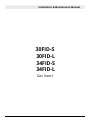
I Series Inserts
INDOOR GAS FIREPLACE
30FID LINEAR
30FID TRADITIONAL
34FID LINEAR
34FID TRADITIONAL
Read and understand this manual. Improper installation, adjustment,
alteration, service or maintenance can cause serious injury, property
damage or even death. For assistance or additional information
consult a qualied installer, service agency or the gas supplier.
A barrier designed to reduce the risk of burns from the
hot viewing glass is provided with this appliance and
shall be installed for the protection of children and other
at-risk individuals.
HOT GLASS WILL
CAUSE BURNS.
DO NOT TOUCH GLASS
UNTIL COOLED.
NEVER ALLOW CHILDREN
TO TOUCH GLASS.
Installer: Leave this manual with the appliance.
Consumer: Retain this manual for suture reference.
NOTICE
DANGER
DANGER
Some materials used in the manufacturing process of this product can
expose you to Benzene which is known in the State of California to
cause cancer and birth defects or other reproductive harm. For more
information go to www.P65warnings.ca.gov
WARNING

XG0528 - 1702232
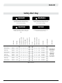
General
PartNumber
Input Rating
Gas Supply Pressure
Manifold Pressure High
Manifold Pressure Low
OriceSize(DMS)
PilotOriceSize(No.)
Electrical Requirement
VentSize
Minimum Vent Length
Maximum Vent Length
EciencyP.4.1-15
Control Type
FuseSpecication
Certication(s)
30FIDN-L-F[NG] 30FIDNIL-01 24,000
7"
WC
3.5" 2.2" 41 62
115VAC,
60Hz
3"OUT
3"IN
10' 36' 77.6% SITProame2
3.15
Amps
AnsiZ21.88-2014/CSA
2.33-2014VENTEDGAS
FIREPLACE HEATERS
CGA2.17-M91
[R2009]GASFIRED
APPLIANCES FOR
HIGH ALTITUDES
CSAP.4.1-09[R2014]
FireplaceEciency
30FIDL-L-F[Propane] 30FIDLIL-01 23,000
11"
WC
10" 6.4" 54 35
115VAC,
60Hz
3"OUT
3"IN
10' 36' 79% SITProame2
3.15
Amps
30FIDN-S-F[NG] 30FIDNIS-01 24,000
7"
WC
3.5" 2.2" 41 62
115VAC,
60Hz
3"OUT
3"IN
10' 36' 78.8% SITProame2
3.15
Amps
30FIDL-S-F[Propane] 30FIDLIS-01 23,000
11"
WC
10" 6.4" 54 35
115VAC,
60Hz
3"OUT
3"IN
10' 36' 80.1% SITProame2
3.15
Amps
34FIDN-L-F[NG] 34FIDNIS-01 31,000
7"
WC
3.5" 2.2" 41 62
115VAC,
60Hz
4"OUT
3"IN
10' 36' 77.4% SITProame2
3.15
Amps
34FIDL-L-F[Propane] 34FIDLIS-01 30,000
11"
WC
10" 6.4" 54 35
115VAC,
60Hz
4"OUT
3"IN
10' 36' 78.5% SITProame2
3.15
Amps
34FIDN-S-F[NG] 34FIDNIS-01 31,000
7"
WC
3.5" 2.2" 41 62
115VAC,
60Hz
4"OUT
3"IN
10' 36' 81.1% SITProame2
3.15
Amps
34FIDL-S-F[Propane] 34FIDLIS-01 30,000
11"
WC
10" 6.4" 54 35
115VAC,
60Hz
4"OUT
3"IN
10' 36' 82% SITProame2
3.15
Amps
Safety Alert Key
Indicates a hazardous situation which, if
not avoided, WILL result in death or serious
injury or property damage.
Indicates a hazardous situation which, if not
avoided, WILL result in minor or moderate
injury.
Indicates a hazardous situation which, if not
avoided, COULD result in death or serious
injury or property damage.
Indicates practices that are important, but
not related to personal injury.
DANGER
CAUTION
WARNING
NOTICE
Figure 1 Specications

XG0528 - 170223 3
General
Contents
Safety Alert Key ....................................................................................................................... 2
Section A: Before You Begin .................................................................................................................. 4
Warranty Information: See Appendix B ............................................................................................... 4
Rating Plate Sample .................................................................................................................................. 5
Rating Plate Location ................................................................................................................................5
Before You Begin.......................................................................................................................................5
Section1:ProductDimensions .............................................................................................. 6
Section 2: Installation Dimentions ....................................................................................... 8
Install Dimensions ..................................................................................................................................... 8
Clearances ..................................................................................................................................................8
Clearances Cont. .......................................................................................................................................9
Non Combustible Board Install .............................................................................................................9
Section 3: Venting ................................................................................................................... 9
Approved Vent Components..................................................................................................................9
Termination ................................................................................................................................................9
Adaptor ........................................................................................................................................................ 9
Connectors .................................................................................................................................................9
Venting ......................................................................................................................................................... 9
Vent Configurations ................................................................................................................................10
Steps for vent connection .....................................................................................................................10
Section 3: Installation ........................................................................................................... 11
Door Installation & Removal .................................................................................................................11
Propane Conversion ...............................................................................................................................12
Converting the gas regulator on the valve ........................................................................................12
Converting the main burner orifice to Propane ..............................................................................14
Converting the pilot burner orifice to Propane ...............................................................................14
Gas line connection ................................................................................................................................15
Emergency Shut-off Valve .....................................................................................................................15
Fuel Supply + Manifold Pressure Checking ......................................................................................15
Faceplate Installation .............................................................................................................................16
Offset Faceplate Installation .................................................................................................................19
CPI [Continuous Pilot Ignition] / IPI [Intermittent Pilot Ignition] Jumper Cable Installation ..20
“Why use CPI mode”?..............................................................................................................................20
The difference between IPI and CPI: ..................................................................................................20
Installing the CPI Jumper Cable ...........................................................................................................20
Levelling the Unit .....................................................................................................................................21
Connecting Power ...................................................................................................................................21
Battery Installation / Replacement......................................................................................................21
Firestones or Fireglass Installation .....................................................................................................21
Speckled Stone Installation...................................................................................................................22
Driftwood Log Set Installation ..............................................................................................................23
Brick Panel Installation ...........................................................................................................................24
Porcelain Panel Installation ..................................................................................................................24
Traditional Log Installation....................................................................................................................25
Initial Operation .......................................................................................................................................27
Pilot Flame Adjustment ..........................................................................................................................27
Master Override Switch .........................................................................................................................27
Aeration Adjustment ..............................................................................................................................29
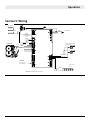
Section5:Wiring ....................................................................................................................30
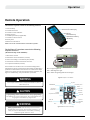
Remote Operation .................................................................................................................31
Initializing the System for the first time ............................................................................................. 32
Operating the System for the first time .............................................................................................32
Continuous Pilot (CPI) Selection (Optional) .......................................................................................32
Temperature Indication Display ..........................................................................................................32
Turn On the Fireplace ............................................................................................................................32
Turn Off the Fireplace ............................................................................................................................32
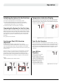
Remote-Flame Control ...........................................................................................................................33
Room Thermostat (Remote Control Operation) ..............................................................................33
Smart Thermostat (Remote Control Operation) .............................................................................33
Disabling Thermostat ............................................................................................................................. 34
Key Lock .....................................................................................................................................................34
Fan Speed Control ..................................................................................................................................34
Accent Light Control ............................................................................................................................... 34
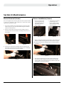
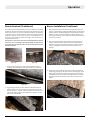
Section 6: Maintenance ......................................................................................................... 35
Burner Removal (Linear) ........................................................................................................................35
Burner Installation (Linear) ...................................................................................................................35
Burner Removal (Traditional) ...............................................................................................................36
Burner Installation (Traditional) ........................................................................................................... 36
Accent Light Replacement (Linear) .....................................................................................................37
Accent Light Replacement (Traditional) ............................................................................................. 37
Optional Fan / Blower Replacement...................................................................................................38
Window Cleaning / Screen Removal ................................................................................................... 40
Battery Replacement .............................................................................................................................. 40
Heat Exchanger Bypass ......................................................................................................................... 40
Pilot Maintenance / Replacement ....................................................................................................... 41
Control Board Replacement .................................................................................................................43
Control Board Fuse Replacement ....................................................................................................... 43
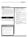
Section 7: Cleaning ................................................................................................................ 44
Cleaning ..................................................................................................................................................... 44
Vent Maintenance / Inspection ............................................................................................................44
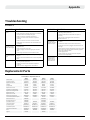
Troubleshooting ..................................................................................................................... 45
Replacement Parts ................................................................................................................45
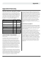
Appendix B: Warranty ...........................................................................................................46
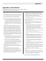
Appendix C: Amendment ......................................................................................................47
(GasFireplace/EquipmentsoldintheStateofMassachusetts) ..................................... 47
Standard Installation Checklist ............................................................................................................51

XG0528 - 1702234
General
IMPORTANT MESSAGE: SAVE THESE INSTRUCTIONS
The I Series replaces must be installed in accordance with these
instructions. Carefully read all the instructions in this manual rst.
Consult the Local Gas Branch to determine the need for a permit prior
to starting the installation. It is the responsibility of the installer to
ensure this replace is installed in compliance with the manufacturers
instructions and all applicable codes.
Warranty Information: See Appendix B
The Montigo warranty will be voided by, and Montigo disclaims any
responsibility for, the following actions:
• Modication of the replace and/or components including Direct-
Vent assembly or glass doors.
• Use of any component part not manufactured or approved by
Montigo in combination with this Montigo replace system.
• Installation other than as instructed in this manual.
Consult your local Gas Inspection Branch on installation requirements
for factory-built gas replaces. Installation & repairs should be done
by a qualied contractor.
This appliance is equipped for altitudes from 0 - 4500 feet [0 -1370 m].
For higher altitudes contact your Montigo dealer.
Do not use this appliance if any part has been under water.
Immediately call a qualied service technician to inspect the appliance
and to replace any part of the control system and any gas control that
has been under water
Due to high temperatures, the appliance should be located out of
trac and away from furniture and draperies
Children and adults should be alerted to the hazards of high surface
temperature and should stay away to avoid burns or clothing ignition
A barrier designed to reduce the risk of burns from the hot viewing
glass is provided with this appliance and shall be installed for the
protection of children and other at-risk individuals
Clothing or other ammable material should not be placed on or near
the appliance
Installation and repair should be done by a qualied service person.
The appliance should be inspected before use and at least annually
by a professional service person. More frequent cleaning might be
required due to excessive lint from carpeting, bedding material, etc. It
is imperative that control compartments, burners, and circulating air
passageways of the appliance be kept clean
NOTICE
NOTICE
NOTICE
NOTICE
NOTICE
NOTICE
Rating Plate Location
Figure 1.2 Rating Plate location
Section A: Before You Begin

XG0528 - 170223 5
General
Rating Plate Sample
Figure 1.1 Rating Plate for 34FID Linear Figure 1.1 Rating Plate for 30FID Traditional
LB1223-V5.2 SIT IPI -with screen AUG.17.2015
Teklynx LabelView Demo
lbl1224-v1.0-sit ipi with screen-for FID SEP.11.2015
Teklynx LabelView Demo
LBA120x Distinction Series no CSA 27-02-2017
LBA120x Distinction Series no CSA 27-02-2017

XG0528 - 1702236
General
27 3/4"
705mm
26 1/4"
667mm
24 1/4"
616mm
26 7/8"
683mm
19 1/2"
497mm
16 5/8"
421mm
14 1/2"
370mm
42"
1067mm
25 3/8"
645mm
13 1/2"
343mm
19 7/8"
506mm
29 1/2"
750mm
13 1/2"
343mm
20"
508mm
5 3/8"
137mm
GAS LINE
ELECTRICAL
Standard Surround
27 3/4"
705mm
26 1/4"
667mm
24 1/4"
616mm
26 7/8"
683mm
19 1/2"
497mm
16 5/8"
421mm
14 1/2"
370mm
42"
1067mm
25 3/8"
645mm
13 1/2"
343mm
19 7/8"
506mm
29 1/2"
750mm
13 1/2"
343mm
20"
508mm
5 3/8"
137mm
GAS LINE
ELECTRICAL
Standard Surround
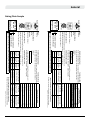
Figure 1.3 Unit dimensions (Tolerance ± ⅛") [1.25 mm]
Figure 1.4 Unit dimensions (Tolerance ± ⅛") [1.25 mm]
Section1:ProductDimensions
A
B
C
D
E
F
G
H
I
J
K
L
M
N
O
26 1/4"
667mm
16 5/8"
421mm
14 1/2"
370mm
27 3/4"
705mm
24 3/8"
619mm
25 3/8"
645mm
26 7/8"
683mm
27 5/8"
702mm
39"
991mm
42"
1066mm
43 1/2"
1105mm
19 1/2"
497mm
19 7/8"
506mm
11 1/2"
291mm
4 1/4"
107mm
28"
712mm
20"
508mm
3 1/4"
83mm
GAS LINE
ELECTRICAL
Set Back Surround
26 1/4"
667mm
16 5/8"
421mm
14 1/2"
370mm
27 3/4"
705mm
24 3/8"
619mm
25 3/8"
645mm
26 7/8"
683mm
27 5/8"
702mm
39"
991mm
42"
1066mm
43 1/2"
1105mm
19 1/2"
497mm
19 7/8"
506mm
11 1/2"
291mm
4 1/4"
107mm
28"
712mm
20"
508mm
3 1/4"
83mm
GAS LINE
ELECTRICAL
Set Back Surround
A
B
C
D
E
F
G
H
I
J
K
L
M
N
P
Q
R
I SERIES STANDARD TRIM DIMENSIONS
A B C D E F G H I J K L M N O
30FID 29½" 19⅞" 13½" 27¾" 26¼" 26⅞" 25⅜" 42" 24¼" 19½" 16⅝" 14½" 5⅜" 20" 13½"
34FID 33½" 23⅞" 14½" 31¾" 30⅜" 30⅞" 29⅜" 46½" 28⅜" 23¼" 20⅛" 18⅛" 5⅜" 23¾" 14½"
I SERIES STANDARD TRIM WITH OFFSET KIT
A B C D E F G H I J K L M N O P Q R
30FID 28" 19⅞" 11½" 4¼" 27¾" 26¼" 27⅝" 26⅞" 25⅜" 43½" 42" 39" 24⅜" 19½" 16⅝" 14½" 3¼" 20"
O

XG0528 - 170223 7
General
27 3/4"
705mm
26 1/4"
667mm
24 1/4"
616mm
19 1/2"
497mm
16 5/8"
421mm
14 1/2"
370mm
29 7/8"
759mm
27 3/8"
695mm
43"
1092mm
47 7/8"
1217mm
13 1/2"
343mm
19 7/8"
506mm
29 1/2"
750mm
20"
508mm
13 1/2"
343mm
5 3/8"
137mm
GAS LINE
ELECTRICAL
Oversize Surround
26 1/4"
667mm
16 5/8"
421mm
14 1/2"
370mm
27 3/4"
705mm
19 1/2"
494mm
29 1/2"
749mm
32"
813mm
39"
991mm
42"
1066mm
24 3/8"
619mm
5 1/4"
133mm
7 3/8"
186mm
13 1/2"
343mm
19 7/8"
506mm
29 1/2"
750mm
20"
508mm
13 1/2"
343mm
5 3/8"
137mm
GAS LINE
ELECTRICAL
4-Sided Surround
27 3/4"
705mm
26 1/4"
667mm
24 1/4"
616mm
19 1/2"
497mm
16 5/8"
421mm
14 1/2"
370mm
29 7/8"
759mm
27 3/8"
695mm
43"
1092mm
47 7/8"
1217mm
13 1/2"
343mm
19 7/8"
506mm
29 1/2"
750mm
20"
508mm
13 1/2"
343mm
5 3/8"
137mm
GAS LINE
ELECTRICAL
Oversize Surround
27 3/4"
705mm
26 1/4"
667mm
24 1/4"
616mm
19 1/2"
497mm
16 5/8"
421mm
14 1/2"
370mm
29 7/8"
759mm
27 3/8"
695mm
43"
1092mm
47 7/8"
1217mm
13 1/2"
343mm
19 7/8"
506mm
29 1/2"
750mm
20"
508mm
13 1/2"
343mm
5 3/8"
137mm
GAS LINE
ELECTRICAL
Oversize Surround
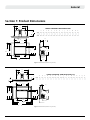
Figure 1.5 Unit dimensions (Tolerance ± ⅛") [1.25 mm]
Figure 1.6 Unit dimensions (Tolerance ± ⅛") [1.25 mm]
A
A
B
B
C
C
D
D
E
E
F
F
G
G
H
H
I
I
J
J
K
K
L
L
M
M
N
N
O
O
P
P
Q
R
I SERIES WITH OVERSIZED TRIM DIMENSIONS
A B C D E F G H I J K L M N O P
30FID 29½" 19⅞" 13½" 27¾" 26¼" 29⅞" 27⅜" 47⅞" 43" 24¼" 19½" 16⅝" 14½" 5⅜" 20" 13½"
34FID 33½" 23⅞" 14½" 31¾" 30⅜" 33⅞" 32⅜" 52" 49" 28⅜" 23¼" 20⅛" 18⅛" 5⅜" 23¾" 14½"
I SERIES WITH FOUR SIDED TRIM DIMENSIONS
A B C D E F G H I J K L M N O P Q R
30FID 29½" 19⅞" 13½" 27¾" 26¼" 32" 29½" 42" 39" 24⅜" 19½" 16⅝" 14½" 7⅜" 5¼" 5⅜" 20" 13½"
34FID 33½" 23⅞" 14½" 31¾" 30⅜" 36" 33" 46½" 43½" 28⅜" 23½" 20⅛" 18⅛" 7⅝" 5⅛" 5⅜" 23¾" 14½"

XG0528 - 1702238
General
10"
254
Max
17"
432
Min
8
1
2
"
216
Min.
Mantel
Side Wall
Hearth Protection
Not Required
Faceplate
17"
432
Minimum
10"
254
Max
Allowable
Mantel
Area
25"
27"
29"
31"
33"
35"
37"
39"
10"
14"
18"
24"
26"30"
34"
38"
21"
19"
17"
23"
24"
610mm
34"
864mm
15"
381mm
Gas and Electrical
Supply at Right Side
6"
152mm
24"
610mm
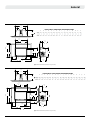
Section 2: Installation Dimentions
Install Dimensions
Clearances
Figure 2.0 Install dimensions
Figure 2.1 Install clearances
A
B
C
D
E
F
G
H
A B C D E F G H
30FID 20" 14" 30" 5" 20" 16" 10" 8½"
34FID 24" 15" 34" 6" 24" 23" 10" 8½"
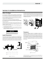
The install size requirements of your replace insert are dependent on
several factors. Gas line location, electrical connection and gas line type
can play into what the minimum installation size can be. The diagram
below illustrates the smallest possible size requirement of this model.
Please take into consideration these other factors when determining
if this appliance will t into your masonry or manufactured replace.
The Insert is designed and built to be installed into masonry or
manufactured replaces. There is no requirement to have a non-
combustible hearth in front of the unit. Clearances to the underside of
the mantel or sidewall are measured from the edge of the door/screen
front. The Mantel is shown as 10” maximum at minimum distance from
the door edge top. The mantel can be extended further providing that
you increase the height proportionately. For instance, if you want a
mantel that is 2” beyond the maximum, you have to install it 2” above
the minimum.
**Hearth protection is not required if the unit is installed with a 2"
(50.8mm) elevation or greater above the hearth surface. See the section
on 4 sided surround options.
Faceplate
Mantel
Hearth
protection not
required**
Gas and electrical
supply at right side
Side wall
Before You Begin
The I-Series insert replaces must be installed in accordance with
these Instructions. Carefully read all the instructions in this manual
rst. Consult the Local Gas Branch to determine the need for a permit
prior to starting the installation. It is the responsibility of the installer to
ensure this replace is installed in compliance with the manufacturers
instructions and all applicable codes.
Installations into a Factory Built Solid Fuel Burning Fireplace
This gas appliance has been tested and approved for installation into
any approved masonry or factory built solid fuel replace, in which
this gas insert will t.
In the event that the vertical height of the factory built replace is less
than 20" you may remove some of the components such as the ue
bae, ue damper or surround panels. These components can be
removed on the condition that:
1). The removal of such components in no way compromises the
structural integrity of the unit.
2). A label supplied with your insert is prominently axed to the existing
replace. This label can be found included in the bag that contains
the back-up batteries for the insert.
The bottom of the existing replace may be removed as long as it does
not compromise the structural integrity of the existing rplace and you
maintain a mandatory minimum ¾" clearance between the bottom of
the insert and the bottom shell of the existing replace. This can be
achieved by using strips of noncombustible material or by using the
leveling bolts on the insert.
This replace has been converted for use with a gas insert replace.
The conversion of this replace voids its original certication and this
appliance can no longer be used as a solid fuel burning replace.
WARNING
REMOVE THIS
SECTION OF
METAL FLOOR
3
4
"
20
MIN.
LEVELING
BOLTS
REMOVE THIS
SECTION OF
METAL FLOOR
3
4
"
20
MIN.
LEVELING
BOLTS

XG0528 - 170223 9
Installation
Section 3: Venting
Termination
Adaptor
Connectors
Venting
NonCombustibleBoardInstall
Clearances Cont.
46DVA-VCH, Duravent Vertical, High Wind Termination
46DVA-CT, Duravent 3" x 3" to 4" x 5 5/8" Co-linear to Co--axial Adaptor
4DFA-FC, Duravent 4" Flex Liner Coupling
3DFA-FC, Duravent 3" Flex Liner Coupling
4" Flex Liner and 3" Flex Liner
10"
254
Max
17"
432
Min
8
1
2
"
216
Min.
Mantel
Side Wall
Hearth Protection
Not Required
Faceplate
17"
432
Minimum
10"
254
Max
Allowable
Mantel
Area
25"
27"
29"
31"
33"
35"
37"
39"
10"
14"
18"
24"
26"30"
34"
38"
21"
19"
17"
23"
10"
254
8"
203
17"
432
Mantel
Side Wall
Hearth Protection
Not Required
Faceplate
17"
432
Minimum
10"
254
Max
Allowable
Mantel
Area
25"
27"
29"
31"
33"
35"
37"
39"
10"
14"
18"
24"
26"30"
34"
38"
21"
19"
23"
Mantle
Side Wall
Gas Insert
Wall Face
Non combustible facing
materials must be used above
the unit, up to the minimum
required mantel height clearance
and for the entire width of the
fireplace opening. This includes
all types of possible installations.
Allowable
mantel area
Gas Insert
Wall face
Side wall
Mantle
Non-combustiblefacing
materialsmustbeusedabove
the unit up to minimum
required mantel height
clearance and for the entire
width of the fireplace opening.
This includes all types of
possibleinstallations.
10"
MAX
30FID16"Min.
34FID23"Min.
Figure 2.2 Install clearances
Figure 2.3 Non Combustible Board Install
Figure 3.0 Approved Vent Components
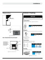
30FID units use 3"x3" venting. 34FID units use 3"x4" venting
NOTICE

XG0528 - 17022310
Installation
Vent Configurations
Stepsforventconnection
This appliance can only be vented vertically. The minimum vent height
measured from the oor under the unit to the bottom of the termination
is 10’. The maximum height that a vent can extend is 36’. The 30FID
uses 3” x 3” Co-linear venting, 34FID uses 4” x 3” Co-linear venting. This
is a direct vent unit and as such requires that both intake and exhaust
vents are connected and operational. Using existing ues as a partial
vent mechanism is not allowed. Due care is required to ensure that all
vent components are properly connected and sealed. Care must also
be taken when installing ashing or termination caps to make sure that
the structure of the building cannot be subject to water penetration.
Proper roong and chimney nishing techniques must be used.
** Before installing the venting system, make sure that any dampers or bae
plates in the replace are removed or do not present any hindrance to your
installation **
1). Determine the length of ex venting that will be required. Cut 2 lengths a
couple of feet longer than you anticipate needing. The length of these needs
to be determined after the vent is stretched out. Flex venting generally comes
compressed and needs to be stretch out to meet the lengths as specied.
2). From the roof, attach the vent lengths to the adaptor. Don't forget to have
the ashing placed between the ex vent and the adaptor before attaching
the ex vent.
3). Using commercial grade sealant around the perimeter of the Collars of the
Adaptor, use a minimum of 3 Tech screws in each Vent.
4). Install the Termination to the top of Adaptor. Use a minimum of 4 tek screws
to attach the Termination to the Adaptor.
5). Feed the ex venting down the chimney until the adaptor is situated near the
top of the chimney. Use a commercial grade of sealant between the ashing
and the chimney top. Fasten the ashing to the top of the chimney using a
fastening method that will properly secure the ashing permanently.
6). Attach the adaptor to the top of the ashing using 4 tek screws. Seal around
the perimeter of the adaptor where it meets the ashing.
7). From inside the house check how long the vents protrude into the replace.
Read the section on installation where fuel supply pressure checking needs
to be done. This procedure can be done at this point by installing the venting
to the appliance prior to pushing the appliance into the replace cavity.
8). Once pre-installation steps have been completed, trim the vent length to
the correct length for installation. The correct length will leave the ue collar
slide plate suspended around 18-19 inches from the oor of the replace.
9). Remove the ue collar slide plate from the appliance. Attach both ex ends
to the Flue Collar Slide plate. Use a commercial high temp sealant around
the Flue Collars on Flue Collar Slide Plate before installing the Venting. Use a
minimum of 3 tech screws to properly secure the Venting to the Flue Collar
Slide Plate.
** Make certain that the Exhaust and Intake Vents are connected to the correct
collars on the Flue Connection Plate. If they are connected in reverse, this
unit will not operate and re-installation will be necessary. **
Termination 46DVA-VCH
Adaptor 46DVA-CT
Flex Liner VT15FL3 BC
(Intake)
Hearth / Floor
Masonry Chimney
(Cut-away View)
Exhaust Flue
Intake Flue
Flashing
Fireplace Insert
Flex Liner VT15FL4 BC
(Exhaust)
Termination46DVA-VCH
Adaptor46DVA-CT
FlexLinerVT15FL3BC(Intake)
FlexLinerVT15FL3BC(30FIDExhaust)
FlexLinerVT15FL4BC(34FIDExhaust)
MasonryChimney(Cut-away
View)
Exhaust Flue
IntakeFlue
Fireplace Insert
Hearth/Floor
Flashing
Figure 3.1 Vent Congurations

XG0528 - 170223 11
Installation
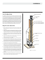
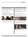
DoorInstallation&Removal
This appliance is supplied with a safety screen installed. The Safety
Screen is attached to the replace door using 4 screws, and can be
removed when necessary for outer glass cleaning.
The Fireplace Door is attached to the Firebox by way of 2 tabs mounted
to the top of the Firebox and by 2 spring loaded retainers at the
bottom underneath the Door. The Retainers at the bottom of the unit
are manipulated using a Door Tool that is supplied with the unit. The
general operation of the Door Retainers is:
Engage door tool into door retainer. Push door tool left, disengaging
the door retainer from the door.
Engage door tool into door retainer. Pull door tool towards you and
push downwards, disengaging the door retainer from the door.
10). Using the Door Opening Tool provided with the Fireplace Insert, insert the
tool through the Outer Shell of the Fireplace Insert. You will be inserting this
tool through a keyhole on front edge of the Flue Collar Slide Plate.
11). The Flue Collar Slide Plate needs to be engaged into the Slide Plate Retainers
as you pull it forward.
12). You will slowly slide the Fireplace Insert back into the Fireplace Cavity. At the
same time, you will be pulling the Flue Slide Plate forward onto the Fireplace
Insert.
** Be extremely careful that the Gasket between the Fireplace Insert and the
Flue Collar Slide Plate is not damaged and remains in the correct position.
Failure of this gasket will greatly diminish the operation of this appliance. **
13). Make certain that when the Flue Collar Slide Plate comes forward that the tab
at the back of the appliance engages into the Flue Collar Slide Plate. Without
this engagement, the Flue Collar Slide Plate will not seal against the Gasket
and the unit will not function.
a). Engage the Door Tool into the Door Retainer
b). Move the Door Tool to the left to release the Door Retainer
c). Move the retainer downward and then back underneath the Door
d). Swing the Door outward from the unit and then lift the Door up and over
the top Tabs
14). Once the Flue Collar Slide Plate is within 1" of the front, Use the 1/4" NC screw
supplied and secure the Flue Collar Slide Plate to the front of the Fireplace
Insert.
Figure 3.2 Vent Connection
Figure 3.2 Vent Slide plate
Figure 3.3 Secure Slide plate
Figure 4.0 Door removal
Section 3: Installation

XG0528 - 17022312
Installation
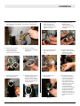
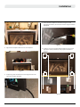
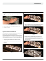
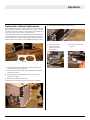
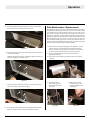
PropaneConversion
Convertingthegasregulatoronthe
valve
Figure 4.1 Propane conversion kit showing
pilot orice, main burner orice, Propane
stepper motor, zap strap and gas tter
conversion label.
Figure 4.2 Propane conversion kit showing pilot orice, main burner orice,
The unit is available in Natural Gas or Liquid Propane versions. If you have
a Natural Gas unit and would like to burn Propane you can purchase an
optional Propane conversion kit and install it using the following steps.
To convert the unit to Propane, the unit must be disconnected from
any gas supply, disconnected from any electrical supply and batteries
and removed from any installation cavity.
The6majoritemsthatneedmodicationtoconvertaunittoPropane:
Tools required:
1. Variable regulator on the
gas valve
2. The main burner orice
3. The pilot burner orice
4. Set minimum primary air
tab
5. Label on the valve showing
the new specications
6. Gas tter conversion label
1. Torx T20 Screw Driver Bit
2. 3/8" Socket Driver
3. 5/32" Allen Key
4. Needle Nose Pliers or Small Flat Head Screw Driver
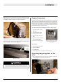
1. On the right side (control side) of the unit, remove 2 screws that
enable the valve to swing away from the unit.
Swing the Door away from the unit, lift over the retaining tabs on top
of the rebox. Be careful to not roll the gasket up o the glass when
reinstalling the door. Installation is the reverse of removal.
Check that the door retainers are properly engaged. If they are not the
door relief system may not operate properly. This can cause a risk of
injury or improper operation of the appliance.
When installing the replace - gas lines, accessories or any other
objects cannot impede the proper movement of the door buckles.
WARNING
Figure 4.1 Door removal

XG0528 - 170223 13
Installation
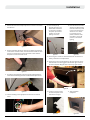
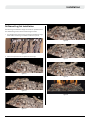
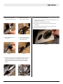
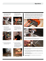
Figure 4.3 Converting the gas regulator on the valve
Figure 4.6 Figure 4.12Figure 4.7
Figure 4.8
Figure 4.4
Figure 4.10
Figure 4.9
Figure 4.5
Figure 4.11
2. Swing the valve away from the unit in order to get access to the
front of the valve and regulator. Be careful not to damage gas
lines or wires.
5. Remove the top 2 screws
that hold the control
mounting bracket in place.
11. Plug the cable into the
control board.
6. Unplug the cable that runs
from the stepper motor
to the control board and
remove it from in between
the control board bracket
and the replace.
12. Reinstall the 2 screws
to secure the top of the
control board mounting
bracket. Using the zip
strap supplied, secure
the excess of wires neatly
within the control / valve
area. Re-install the 2
screws that keep the
valve body from swinging
out from the unit. When
swinging valve back in
use care to not pinch or
kink wires or pilot gas line.
Inspect pilot gas line for
leaks.
7. Place the Propane stepper
motor onto the valve
being extremely careful
that the orientation of the
regulator is correct.
3. Using a T20 Torx screw
driver, remove the 2
screws that attach the
stepper motor to the valve.
9. Attach the label provided
to the side of the valve
body.
8. Reinstall the 2 screws
supplied with the
conversion kit to fasten
the stepper motor to the
valve body.
4. Remove the screws,
stepper motor and rubber
diaphragm.
10. Run the cable from the
stepper motor in between
the control mounting
bracket and replace.

XG0528 - 17022314
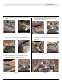
Installation
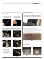
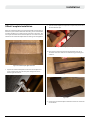
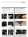
Convertingthemainburnerorificeto
Propane
ConvertingthepilotorificetoPropane
Figure 4.12
Figure 4.16 Figure 4.16
Figure 4.20
Figure 4.14 Figure 4.14 b
Figure 4.13
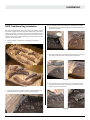
Figure 4.17
Figure 4.21
Figure 4.18
Figure 4.19
13. Remove burner, see
burner removal section.
Using a socket wrench and
driver, loosen and remove
the main burner orice.
16. Using an Allen key, remove the NG Pilot Orice
24. Remove rating plate from
under appliance and turn
it over to the blank side.
19. Reverse steps to install pilot hood.
21. Connect the unit to the gas and electrical supply.
15. Remove the spring clip that retains pilot hood. Remove hood
14. Place the Propane main
orice into the end of the
socket wrench. Being sure
not to cross thread the
orice, install the orice
into the mounting within
the air shutter box.
17. Replace the NG Pilot
orice with the Propane
Pilot orice. If you get
the orices mixed up, the
Propane orice has a
grove machined around
the diameter near the end.
25. Apply sticker to blank side.
Put rating plate back.
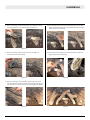
20. The minimum primary air setting is dierent depending on fuel
and burner. The minimum primary air is set by hand-bent tabs
on the primary air adjustment. Bend the appropriate tab down
for your fuel and burner. See specications table or primary air
adjustment for proper tab. See image below for tab lengths. If
your setting is fully closed, bend both tabs up.
22. Before concluding the conversion, make sure you leak test the
entire system and check all operational functions to ensure that
the unit is performing safely and properly.
23. Fill out required information on Propane conversion label.
1/16"
LINEAR
LINEAR TRADITIONAL
TRADITIONAL
3/16"

XG0528 - 170223 15
Installation
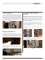
Gas line connection Fuel Supply + Manifold Pressure
Checking
EmergencyShut-offValve
Figure 5.3
Figure 5.5
Figure 5.0
Figure 5.1
Figure 5.2
Figure 5.4
The Insert is supplied with a exible gas line that uses a ½” female are
to connect to your service. The exible gas line is a one time connection.
If you ever have to break the connection, you must replace the exible
gas line. There is also a safety shuto valve that is built in and operated
when needed used the door removal tool. Depending on your local
gas codes, you may need to provide an additional gas shut o valve
or even hard pipe the unit. In the event that you need to hard pipe the
gas supply, a union will be required.
It’s imperative that you verify that the supply pressure to your appliance
is adequate and that the valve is supplying the correct pressure to the
pilot and main burner. The pilot burner operates at line pressure and
may need further adjustment. The valve outlet pressure is set by the
manufacturer of the valve but should be veried upon install. Follow
the following steps to perform this system check. Inlet pressure must
be checked with replace burning.
This appliance is equipped with a shut-o valve for use in case of
emergency. It is located on top of the appliance gas valve and can be
accessed and operated through the front of the replace using the
door tool. The appliance is shipped from the manufacturer with the
emergency shut-o valve in the closed position.
HOOK DOOR
TOOL HERE
PULL THIS
DIRECTION TO OPEN
Hook the door tool into the arm of the emergency shut-o valve. Pull
the door tool towards you to open the valve and push it away from
you to close the valve.
1. Remove the 2 screws from the Valve Mounting Bracket so that
the valve can be swung away from the unit. The Shut o lever
needs to be in the “o” position to be able to swing the valve out
of the valve control box.
3. Attach a silicone hose to over top of the pressure tap on the
valve face. Connect the hose to a manometer.
2. Using a slotted screw driver, loosen the Manifold Tap on the
valve front.

XG0528 - 17022316
Installation
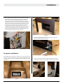
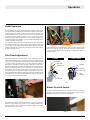
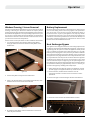
Faceplate Installation
The Faceplate Surround has two main parts: the rear panel and the
front panel. The rear panel has a master override switch installed on
the upper right corner. The rear panel has to be installed prior to the
front panel.
4. The emergency Shut-o valve needs to be placed in the “ON”
position, see section for operation. The pressure tap on the
left is to be used to measure supply line pressure. Refer to
the specications at the beginning of this manual for the gas
pressure specs. Be sure to close and leak test all potential leak
areas prior to closing in the install. Using the remote, turn the
main burner on. Check the inlet pressure and the manifold
pressure on high and low. Refer to specication sheet for
acceptable values. Remove rubber tubes, close taps and check
for leaks. Close emergency shut-o valve reinstall the valve
mounting bracket. Make sure wires and pilot gas lines are not
pinched or kinked. Check pilot gas line for leaks.
Figure 5.6
Figure 5.8
Figure 5.9
Figure 5.10 Figure 5.11
Figure 5.7
FOUND BEHIND PANEL
1. Remove the Lighting Instructions from the Control area and
leave on the oor in front of the unit.
2. Install the Rear Faceplate Panel support brackets using screws
provided (4 locations). Ensure proper orientation of the bracket.

XG0528 - 170223 17
Installation
Figure 5.12
Figure 5.13
Figure 5.15
Figure 5.16
Figure 5.14
3. Align the Rear Faceplate with the front of the replace.
5. Attach the Rear Faceplate to the Firebox using the screws
provided (18 locations). Do not insert screws in magnet locations
highlighted.
6. Install the four Front Faceplate Retainer Magnets using screws
provided as shown (8 locations). Note proper orientation of
magnets.
4. Temporarily, place the Electrical Cord through the hole in the
right side of the Rear Faceplate

XG0528 - 17022318
Installation
Figure 5.17
Figure 5.21
Figure 5.24 Figure 5.25
Figure 5.22
Figure 5.18
Figure 5.19
Figure 5.23
Figure 5.20
7. Remove the twist tie and Zap Strap that is on the On / O Switch
wire harness.
11. Place the Zip Strap
through the hole in the
Plastic Stick on Retainer
on the back of the Rear
Faceplate. Zip the wires
together in one tidy
package as shown.
11. Hooks are used to secure
the Front Faceplate at the
bottom left and right.
11. Trim installation
completed.
12. Place the master override
switch in the OFF position.
Until the remote is synced
to the control board, this
switch acts as a master.
If you apply gas and
power to the unit while
this switch is in the ON
position, it will initiate
lighting.
8. Slip the Split Plastic Grommet, found in the plastic bag attached
to the master override switch, around the Power Cable and then
press it into the provision on the right lower side of the Rear
Faceplate to secure the Power Cord.
9. Thread the On/O Wire Harness through the gap between the
Control Board Mounting Bracket and the Rear Faceplate Panel.
13. At this stage it is easiest to install the batteries. See section on
battery installation and replacement.
14. The Front trim can now be installed. It has two fasteners at the
bottom which must be engaged in the bottom right and left of
the Front Faceplate. Magnets hold it at the top right and left.
10. Connect the Plug to the appropriate terminal on the Control
Panel.

XG0528 - 170223 19
Installation
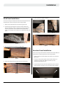
Offset Faceplate Installation
When the standard faceplate is used the install width of the replace is
30 inches. If your install is smaller than 30 inches, you can use the oset
kit, which will allow you to decrease the install size to 28 inches. This
can only be done with the standard faceplate kit. You must install the
oset kit on the standard faceplate before installing it on the appliance.
Figure 5.12a Standard Faceplate Oset Kit Contents
Figure 5.12a Cutting away excess material
Figure 5.12b Peeling self-adhesive tape
Figure 5.12c
Figure 5.12d
1. Unpack the standard faceplate kit. Take the rear faceplate and
cut 5/16 inches away from the wire pass-through hole at the
bottom right hand corner.
2. Take the oset faceplate and peel the red protective plastic o of
the self-adhesive tape.
3. Place the rear panel from the standard faceplate over top of
the oset trim. Press down on the adhesive to guarantee good
adhesion.
4. Continue to standard faceplate installation section for remainder
of installation.

XG0528 - 17022320
Installation
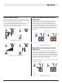
CPI[ContinuousPilotIgnition]/IPI[IntermittentPilotIgnition]JumperCable
Installation
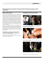
“Why use CPI mode”?
There are several reasons why you may choose to use CPI mode. When
a ue is cold it can be dicult to light the appliance. It can take a bit of
time (particularly on tall vents) to initialize vent action. This can result
in “lifting” or “ghosting” of the ames during the rst two to three
minutes of operation. It is also possible to encounter times when the
replace fails to light successfully. The replace will then attempt to
re-light a second or third time depending on prevailing temperatures
or altitude. When in CPI mode the pilot also keeps the system warm.
During a “cold” start, condensation will normally form on the inner glass
surface of the door. This condensation will quickly dry, however, the
condensation tends to run down the glass and cause some streaking.
CPI mode helps to resolve this issue. If CPI mode is used during the
winter months the energy it takes to run the pilot is partially recovered
as heat into the building, so it does not waste as much energy as running
a pilot in the o season.
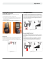
A connector is supplied with this unit that can be plugged into the
wire harness connected to the controller. This Jumper Cable gives the
Remote Control the ability to operate the CPI / IPI switch and set the
unit to operate in either condition. CPI means “Continuous Pilot Ignition”
or “Standing Pilot” as it is commonly known. IPI means “Intermittent
Pilot Ignition”, which only initializes the pilot when you are going to be
using the appliance.
ThedifferencebetweenIPIandCPI:
IPI(IntermittentPilotIgnition)Mode:is a fuel saving mode in
which the pilot is only used when the main burner is on.
CPI(ContinuousPilotIgnition)Mode:The pilot runs continuously
even when the main burner is o.
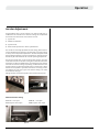
InstallingtheCPIJumperCable
1). Open the control box drawer.
2). Remove the bag containing the Jumper Cable from the wire
harness connected to the controller.
3). Find the corresponding plug attached to the control wire harness
and connect the CPI jumper.
4).See operation section to turn remote into CPI mode.
Figure 6.0
Figure 6.1 Locate Jumper cable
Figure 6.2 Connect CPI
Page is loading ...
Page is loading ...
Page is loading ...
Page is loading ...
Page is loading ...
Page is loading ...
Page is loading ...
Page is loading ...
Page is loading ...
Page is loading ...
Page is loading ...
Page is loading ...
Page is loading ...
Page is loading ...
Page is loading ...
Page is loading ...
Page is loading ...
Page is loading ...
Page is loading ...
Page is loading ...
Page is loading ...
Page is loading ...
Page is loading ...
Page is loading ...
Page is loading ...
Page is loading ...
Page is loading ...
Page is loading ...
Page is loading ...
Page is loading ...
Page is loading ...
Page is loading ...
-
 1
1
-
 2
2
-
 3
3
-
 4
4
-
 5
5
-
 6
6
-
 7
7
-
 8
8
-
 9
9
-
 10
10
-
 11
11
-
 12
12
-
 13
13
-
 14
14
-
 15
15
-
 16
16
-
 17
17
-
 18
18
-
 19
19
-
 20
20
-
 21
21
-
 22
22
-
 23
23
-
 24
24
-
 25
25
-
 26
26
-
 27
27
-
 28
28
-
 29
29
-
 30
30
-
 31
31
-
 32
32
-
 33
33
-
 34
34
-
 35
35
-
 36
36
-
 37
37
-
 38
38
-
 39
39
-
 40
40
-
 41
41
-
 42
42
-
 43
43
-
 44
44
-
 45
45
-
 46
46
-
 47
47
-
 48
48
-
 49
49
-
 50
50
-
 51
51
-
 52
52


Montigo 34FID-01 / 30FID-01 Insert Operating instructions
- Category
- Fireplaces
- Type
- Operating instructions
- This manual is also suitable for
Ask a question and I''ll find the answer in the document
Finding information in a document is now easier with AI
Related papers
-
Montigo RFKFID User manual
-
-
-
-
-
-
-
Montigo XT0021 Proflame 2 Remote Kit Installation guide
-
-
Other documents
-
QOLSYS QR0018-840 Quick start guide
-
FMI GWMT1 Operating instructions
-
 Fireplace SIT Proflame 2 Remote Control User manual
-
Stelpro ET120 User guide
-
Scotsman CME306, CME456 - KSTAT-22 Bin Thermostat Kit - 17-2817-01 Operating instructions
-
Dynasty Electric Installation guide
-
Whitehall Products 00939 Installation guide
-
Unbranded CAM50RECWMEF-2WHT User manual
-
Dimplex DFO2307 User manual
-
Solstice Sculptures DUCK STATUE DRIFTWOOD EFFECT User manual
