Montigo XT0021 Proflame 2 Remote Kit Installation guide

Type
Installation guide
Upgrade Kit
Proame 2 Remote Kit
Page 1 XT0021 - 151127.1
The installation of this kit must be done by a qualied and
certied gas appliance installer.
Check local codes and read all instructions prior to instal-
lation.
Ensure that all power to the appliance is off at the electrical breaker or fuse
before beginning installation. Ensure gas is turned off at the shutoff valve before
beginning installation.
CAUTION
This kit is for use with the following models:
H*34**-F : H*34 Series with IPI Electronic Ignition
H*38**-F : H*38 Series with IPI Electronic Ignition
H*42**-F : H*42 Series with IPI Electronic Ignition
L38-DF(-ST)-F : L38DF with IPI Electronic Ignition
L42-DF(-ST)-F : L42DF with IPI Electronic Ignition
L52-DF(-ST)-F : L52DF with IPI Electronic Ignition
®
C
US
Warning: If the information in these instructions is not followed
exactly, a fire or explosion may result causing property damage,
personal injury or loss of life.
Do not store or use gasoline or other flammable vapors and liquids in the
vicinity of this or any other appliance.
 What To Do If You Smell Gas:
Do not try to light any appliance.
Do not touch any electrical switch; do not use any phone in your building.
Immediately call your gas supplier from a neighbor's phone. Follow the gas
supplier's instructions.
If you cannot reach your gas supplier, call the fire department.
Installation and service must be performed by a qualified installer, service agency or
the gas supplier.
Upgrade Kit NG/LP Proame 2 Standard to
Remote Control
* = C, L, P, R, W
** = DF or DL, Single Sided or See Through
WARNING
When installing the replace - gas lines, ttings, accesso-
ries or any other objects cannot impede the proper
movement of the door buckles.
Some materials used in the manufacturing process of this product can
expose you to Benzene which is known in the State of California to
cause cancer and birth defects or other reproductive harm. For more
information go to www.P65warnings.ca.gov
WARNING
Installation
Page 2
XT0021 - 151127.1
General Information
This kit is for installation with the models listed above.
KIT # Contents
PF2RK Remote Control, Manual Override switch with har-
ness
and bracket, backup battery pack, Proame 2 opera-
tions
manual, hardware and batteries.
Before You Begin
Ensure that the power supply has been turned off at the breaker
or fuse before beginning the installation.
Shut off the gas supply at the shut-off valve, and ensure that the
main burner and pilot light have been turned off and the re-
place has been cooled off for at least two hours before installa-
tion.
General Information
This kit contains the necessary components for upgrading the Pro-
flame 2 standard unit to operate with Remote Control.
The installation of this unit must also conform with local codes or, in
the absence of local codes, with the American National Fuel Gas
Code, ANSI Z223.1, or the Canadian Installation Code, CAN / CGA
B149.
Tool Required
Impact gun / Drill
1/4 " Nut driver bit
WARNING!
This upgrade kit shall be installed by a qualified service
agency in accordance with the manufacturer's instructions
and all applicable codes and requirements of the authority
having jurisdiction. If the information in these instructions
are not followed exactly, a fire, explosion or production of
carbon monoxide may result causing property damage,
personal injury or loss of life. The qualified service agency
is responsible for the proper installation of this kit. The
installation is not proper and complete until the operation
of the converted appliance is checked as specified in the
manufacturer's instructions supplied with this kit.
Note
Upon successful installation of this upgrade kit, the following
features are available for the user:
1. Thermostatic and smart thermostatic control of the re-
place
2. Main burner ame modulation (6 levels)
3. Choice of Standing or Intermittent pilot (CPI switch or
jumper required)
4. Comfort fan speed modulation (Remote Fan Kit RFK50R
required)
5. Battery backup for the main burner during power outage
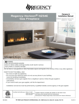
Note: You may remove the front cover (See Figure 2), or the
burner assembly to access the control module and wiring. If
removed, please ensure it is re-installed properly and all gas
connections are leak tested.
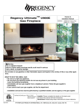
Remote Control
Battery Pack
Manual override
switch with harness
and bracket
Proame 2 Operations
Manual
Figure 1 Contents of Proame 2 Upgrade Kit
Hardware and
batteries
Contents
A. Disconnect wire from existing module: 3
B. Control Module Connection: 3
C. Main ON/OFF Switch Installation: 3
D. Battery Holder Installation: 4
E. Operation with Backup Battery: 4
F. Operation with Main Power: 4
G. CPI / IPI Jumper Cable Installation 5
Figure 2 Fireplace front cover
Remote Control
Installation
Page 3XT0021 -151127.1
A. Disconnect wire from existing module:
1. Remove valve blind and glass door.
Figure 3 Control module with wires
B. Control Module Connection:
1. Connect the Manual ON/OFF switch to X4.
Figure 4 X4 plug on control module
Figure 5 Attach switch bracket to front of replace
C. Main ON/OFF Switch Installation:
1. Position the Main/off Switch bracket on the right leg of the
firebox as shown in Figure 5 and Figure 6
2. Using the two selftapping screws supplied attach the bracket.
See Figure 6.
3. Feed the switch and the wires through the slot in the bracket as
shown and install the switch to the bracket. See Figure 7.
4. Secure the wires to the floor of the fireplace using the supplied
cable tie and cable tie mounts.
5. Attach the "Main ON/OFF" label supplied to the valve bracket.
Figure 6 Attach switch bracket to front of replace
Figure 7 Attach switch to bracket.
X4 Control
Module
Connect Manual ON
OFF switch here
Installation
Page 4
XT0021 - 151127.1
F. Operation with Main Power:
1. Follow the instructions on the "Proame2 Operation and Main-
tenance Manual- XG0677" to install batteries on the remote
control.
2. Turn the gas supply ON.
3. Turn the Main Power to ON.
4. Program the remote control to the control module (see "Pro-
ame2 Operation and Maintenance Manual- XG0677").
5. Turn the fireplace ON and modulate the flame using the remote
control and ensure proper operation (see "Proame 2 Opera-
tion and Maintenance Manual XG0677").
D. Battery Holder Installation:
1. Secure the battery holder to the fireplace floor using the supplied
velcro strips. See Figure 9.
Note: The velcro strips act as an electrical isolation, do not attach
the battery holder to any metal part without using the velcro strips, or
the control module will be damaged.
2. Connect the red and black wires from the battery holder to the
red and black wires from the valve harness. See Figure 10.
Figure 8 Attach switch to bracket
Figure 9 Battery holder
E. Operation with Backup Battery:
1. Install the four supplied AA batteries to the battery holder.
CAUTION: Please note battery orientation while installing them.
Incorrect orientation may damage battery, cause fire hazard and the
fireplace may not function properly.
2. Follow the instructions on the "Proame2 Operation and Main-
tenance Manual- XG0677" to install batteries on the remote
control.
3. Turn the gas supply ON.
4. Program the remote control to the control module (see "Pro-
ame2 Operation and Maintenance Manual- XG0677").
5. Check the stepper motor for gas leaks and ensure no leak.
6. Turn the fireplace ON and modulate the flame using the remote
control and ensure proper operation (see "Proame 2 Opera-
tion and Maintenance Manual XG0677").
Blue Back lit LCD display
On/Off Key
Thermostat Key
Up/Down Arrow Key
Mode Key
Figure 10 Battery holder wires
Figure 11 Proame Remote Control
Installation
Page 5XT0021 -151127.1
Installing the CPI Jumper Cable
1). Access the controller (refer to the installation and
maintenance manual for your model).
2). Remove the bag containing the Jumper Cable from
the wiring harness connected to the controller as shown
in Figure 12.
3). Find the corresponding plug attached to the control
wire harness and connect the CPI jumper.
4). See remote operation manual to turn remote into CPI
mode.
Figure 12.
Figure 12a.
Figure 12b.
G. CPI / IPI Jumper Cable Installation
(only available for SIT Electronic Ignition Systems)
“Why use CPI mode”?
CPI means “Continuous Pilot Ignition” or “Standing Pilot”
as it is commonly known. IPI means “Intermittent Pilot Ig-
nition”, which only initializes the pilot when you are going
to be using the appliance.
There are several reasons why you may choose to use
CPI mode. When a ue is cold it can be difcult to light
the appliance. It can take a bit of time (particularly on tall
vents) to initialize vent action. This can result in “lifting”
or “ghosting” of the ames during the rst two to three
minutes of operation. It is also possible to encounter
times when the replace fails to light successfully. The
replace will then attempt to re-light a second or third
time depending on prevailing temperatures or altitude.
When in CPI mode the pilot also keeps the system warm.
During a “cold” start, condensation will normally form on
the inner glass surface of the door. This condensation will
quickly dry, however, the condensation tends to run down
the glass and cause some streaking. CPI mode helps to
resolve this issue. If CPI mode is used during the winter
months the energy it takes to run the pilot is partially re-
covered as heat into the building, so it does not waste as
much energy as running a pilot in the off season.
If you use a wall switch:
A connector is supplied with this unit that can be plugged
into the wire harness connected to the controller. When
the CPI jumper is connected, the pilot will light and re-
main lit continuously. Use the wall switch to turn the main
burner on or off. To switch back to IPI mode you must
unplug the CPI jumper.
If you use the remote:
A connector is supplied with this unit that can be plugged
into the wire harness connected to the controller. This
Jumper Cable gives the Remote Control the ability to
operate the CPI / IPI switch and set the unit to operate in
either condition.
The difference between IPI and CPI:
IPI (Intermittent Pilot Ignition) Mode: is a fuel sav-
ing mode in which the pilot is only used when the main
burner is on.
CPI (Continuous Pilot Ignition) Mode: The Pilot runs
continuously even when the main burner is off.
XT0021 - 151127.1
Proflame 2 Upgrade Kit
  • Page 1 1
  • Page 2 2
  • Page 3 3
  • Page 4 4
  • Page 5 5
  • Page 6 6

Montigo XT0021 Proflame 2 Remote Kit Installation guide

Type
Installation guide

Ask a question and I''ll find the answer in the document

Finding information in a document is now easier with AI