Page is loading ...

SB-2-584-R1 (10/2020) 1 / 16 www.carlisleft.com
Replacement Parts Ordering Information SEE PAGE 4
Explanation of Conventional, Trans-Tech and HVLP SEE PAGE 9
Complete Spray Gun Assembly Ordering Information SEE PAGE 10
Installation Details SEE PAGES 11, 13, 14, 15
COMPACT-X
AUTOMATIC SPRAY GUN
CONVENTIONAL (SILVER)
TRANS-TECH (GREEN)
HVLP (BLUE)
EN
SERVICE MANUAL

EN
SB-2-584-R1 (10/2020)2 / 16www.carlisleft.com
Operation Manual
Compact-X Automatic Spraygun
Important
Read and follow all instructions and Safety Precautions before using
this equipment
CHARACTERISTICS
This automatic spray gun complies to ATEX regulations
94/9/EC, protection level II 2 G X, suitable to use in Zones
1 & 2.
This Compact-X spray gun is a production spray gun
suitable for use with automatic and semi-automatic
machines in conventional, HVLP or Trans-Tech
applications. (See page 9 for application details.)
Compact-X has a ¼ turn Quick detachable manifold,
so to reduce maintenance & set up time. To handle a
wide range of coating materials the fluid passages are
manufactured from high grade stainless steel. Several
needles are available with plastic tips.
This spray gun can be provided with an indexed air cap
(order separately.) You can leave your air cap capable
of free rotation by removing the indexed plastic ring
which is located by 2 pins on the air cap. Pressure feed
material supply can be re-circulating or direct.
The needle adjustment knob has 18 ratchet positions
(per one revolution of the knob) which allows fine and
accurate fluid flow control.
SPECIFICATIONS & MATERIALS OF CONSTRUCTION
Thread Pressure
Fluid inlet & recirculation “P” & "R" 1/8" BSPP(F) Max 7 Bars (100 psi)
Air inlet (Atom+Fan) “A” & “F” 1/8" BSPP(F) Max 7 Bars (100 psi)
Cylinder/trigger “Cyl” 1/8" BSPP(F) 4 to 7 Bars (60-100 psi)
Maximum temperature in use 40° C (104° F)
Spray gun weight 950 gms (2 lbs)
Gun body Aluminium hard anodized
Tip / Needle / Spray head/ Base plate Stainless steel 303
EC Declaration of Conformity
We, Finishing Brands UK, Ringwood Rd, Bournemouth, Dorset, BH11 9LH, UK, as the manufacturer of
the Spray gun model COMPACT-X, declare, under our sole responsibility that the equipment to which
this document relates is in conformity with the following standards or other normative documents:
BS EN 292-1 PARTS 1 & 2: 1991, BS EN 1953: 1999; and thereby conform to the protection requirements
of Council Directive 98/37/EEC relating to Machinery Safety Directive, and; EN 13463-1:2001, council
Directive 94/9/EC relating to Equipment and Protective Systems intended for use in Potentially
Explosive Atmospheres protection level II 2 G X.
D. Smith, General Manager
12th February 2014
DeVilbiss reserves the right to modify equipment specification without prior notice.

EN
SB-2-584-R1 (10/2020) 3 / 16 www.carlisleft.com
FIRE AND EXPLOSION
Solvents and coating materials can be highly flammable or combustible when sprayed. ALWAYS refer
to the coating material supplier's instructions and MSDS sheets before using this equipment.
Users must comply with all local and national codes of practice and insurance company requirements
governing ventilation, fire precautions, operation and house-keeping of working areas.
This equipment, as supplied, is NOT suitable for use with Halogenated Hydrocarbons.
Static Electricity can be generated by fluid and/or air passing through hoses, by the spraying process
and by cleaning non- conductive parts with cloths. To prevent ignition sources from static discharges,
earth continuity must be maintained to the spraygun and other metallic equipment used. It is essential
to use conductive air and/or fluid hoses.
PERSONAL PROTECTIVE EQUIPMENT
Toxic vapors – When sprayed, certain materials may be poisonous, create irritation or be otherwise
harmful to health. Always read all labels, safety data sheets and follow any recommendations for the
material before spraying. If In doubt, contact your material supplier.
The use of respiratory protective equipment is recommended at all times. The type of equipment must
be compatible with the material being sprayed.
Always wear eye protection when spraying or cleaning the spray gun
Gloves must be worn when spraying or cleaning the equipment.
TRAINING
Personnel should be given adequate training in the safe use of spraying equipment.
MISUSE
Never aim a spray gun at any part of the body.
Never exceed the max. recommended safe working pressure for the equipment.
The fitting of non-recommended or non-original spares may create hazards.
Before cleaning or maintenance, all pressure must be isolated and relieved from the equipment.
The product's metal parts can be cleaned using a gun-washing machine. However, this equipment
should not be left inside gun-washing machines for prolonged periods of time. Certain selas and
o-rings may not be solvent compatible.
NOISE LEVELS
The A-weighted sound level of spray guns may exceed 85 dB (A) depending on the set-up being used.
Details of actual noise levels are available on request. It is recommended that ear protection is worn at
all times when spraying.
OPERATING
Spray Equipment using high pressures may be subject to recoil forces. Under certain circumstances,
such forces could result in repetitive strain injury to the operator.
SAFETY WARNINGS

EN
SB-2-584-R1 (10/2020)4 / 16www.carlisleft.com
PARTS LIST
For the arrangement of the parts, refer to the exploded view on page 5.
Item Description Order
Part Number Qty
1 See chart and reference on page 6.
Air cap with retaining ring, seals and no indexing ring. SP-100-xxx-K 1
2
Fluid tip with air separator seal SPA-27-K5
Ø 0.85 / 1.0 / 1.4 / 1.8 / 2.2 mm
Ø 0.5 for Air cap 590 Ø 0.7 mm for Air cap 591
SP-200S-xx-K
SP-259S-xx-K
1
4Locator ring for indexed air cap (optional item) SPA-112 1
5Air separator seal (kit of 5 rings) SPA-27-K5* 1
6Screw M4 x 25 kit of 4 (Torx 20) — (kit includes items 6, 8a, 12a) SPK-108* 4
8 Spray head – Compact-X SPA-50P 1
8a Fixing rod on base plate (kit includes items 6, 8a, 12a) SPK-108* 1
9Packing seal for needle (kit includes items 9, 11) SPK-107* 1
10 O-ring (kit includes items 10, 12b) SPK-109* 4
11 O-ring gasket (kit includes items 9, 11n)SPK-107* 2
12 Gun body for Compact-X ( -S = Silver / -G = Green / -B = Blue )
SPA-1-CMAX-S
SPA-1-CMAX-G
SPA-1-CMAX-B
1
12a Locating air tube (kit includes items 6, 8a, 12a) SPK-108* 1
12b O-ring (kit includes items 10, 12b) SPK-109* 1
13 Air valve (Fan & Atomising air) AGG-403 2
14 O-ring (kit includes items 14, 15c, 15d, 16) SPK-104* 1
15 Piston assembly (includes items 14, 15b, 15c, 15d, 16) SPA-60X-K 1
15b Piston for air valve (kit includes qty. 2) SPA-60X-K 1
15c O-ring for small piston (kit includes items 14, 15c, 15d, 16) SPK-104* 2
15d O-ring for large piston (kit includes items 14, 15c, 15d, 16) SPK-104* 1
16 O-ring piston to needle (kit includes items 14, 15c, 15d, 16) SPK-104* 1
17 Piston Spring (kit includes items 17, 22, 23, 24) SPK-105* 1
18 Stainless steel needle 0.5 / 0.7 / 0.85 / 1.0 / 1.4 / 1.8 / 2.2
Plastic tip 1.0 / 1.4
SPA-320-xx
SPA-320P-xx 1
19 Housing SPA-3 1
20 Ring and ball (2) — (kit includes items 20, 21, 25) SPK-106* 1
21 Ring (kit includes items 20, 21, 25) SPK-106* 1
22 Needle Spring (kit includes items 22, 23, 24) SPK-105* 1
23 Spring cap (kit includes items 22, 23, 24) SPK-105* 1
24 Spring washer (kit includes items 22, 23, 24) SPK-105* 1
25 Adjusting knob (kit includes items 20, 21, 25) SPK-106* 1
27 Manifold assembly – complete with lever and air valves SPA-55-K 1
28 Locking lever (kit includes items 28, 28a & 8a) SPA-56-K* 1
28a Retaining screw of locking device (kit includes items 28, 28a & 8a) SPA-56-K* 1
29 Gun mounting bar nut (kit includes items 29, 30 & 31) SPK-110* 1
30 Gun mounting bar (kit includes items 29, 30 & 31) SPK-110* 1
31 M6 hexagon socket head cap screw, length 5.5 (kit includes items 29, 30 & 31) SPK-110* 2
32 Kit of 2 plugs which replace manual air valve (13) — for remote fan/atom SPA-111-K2* 1
33 Kit of retaining ring with gasket (kit includes air cap ring and gaskets) SPK-102-K* 1
34 Recirculation Port Plug (kit includes hex wrench SPA-30) SPK-116* 1
35 Manifold Plug, 1/8" BSPP (not sold as a spare part) REF. 1
Item 9: Fluid packings only (10 pack) SPA-86-K10.
Optional: Fluid packings (2 pack) SPA-20-K2
* Spare parts must be ordered as part of replacement kits listed above.
See page 10 for additional adapter and fitting kits.
n Item 11: Air gaskets only (10 pack) SPA-53-K10.

EN
SB-2-584-R1 (10/2020) 5 / 16 www.carlisleft.com
COMPACT-X AUTOMATIC SPRAY GUN
COMPACT-X AUTOMATIC GUN
EXAMPLE OF PART NUMBERING SYSTEM
CMAX–B85PM–507
CMAX– B 85 P M 507
Compact-X
Automatic
Manifold Type
Spray Gun
B = Blue (HVLP)
G = Green
(Trans-Tech)
No Letter =
Conventional
85 = .85 mm Fluid Nozzle
and Needle
00 = No Fluid Nozzle,
No Needle
P = Plastic Needle
– or no letter = Stainless
Steel
Needle
M = With Manifold
O = No Manifold
507 = Air Cap
NOTE: SPN-8 Torx Wrench for item 6 shipped with gun.
SPA-30 Hex Wrench for item 34 shipped with gun.
SPN-8 and SPN-30 not shown on exploded view above.
See page 10 for standard set-ups.
See page 11 for hook-up schematic.
REF. ONLY:
• SPA-60X-K (includes items 14, 15b, 15c, 15d, 16)
• SPK-104 (includes items 15c–qty.10, 15d–qty.5, 16–qty.10, 14–qty.5)
• SPK-105 (includes items 17, 22, 23, 24)
• SPK-107 (includes items 9, 11)

EN
SB-2-584-R1 (10/2020)6 / 16www.carlisleft.com
COMPACT-X AUTOMATIC GUN — AVAILABLE AIR CAPS
Air cap Type Air Flow Pressure
at Inlet Fluid Flow Pattern size
@ 8" distance
SCFM l/min psi bar oz/min ml/min in mm
SP-100-430-K Conventional 12 340 50.7 3.5 6.7 - 9.5 200 - 280 7.9 200
SP-100-443-K Conventional 12.2 345 43.5 3.0 6.7 - 10.1 200 - 300 11.8 300
SP-100-497-K Conventional 18 510 50.7 3.5 6.7 - 20.2 200 - 600 15.0 380
SP-100-500R-K HVLP Round Spray 6.8 200 16.0 1.1 .6 - 5.0 20-150 1.6 40
SP-100-507-K H V L P 19 385 40 1.4 4.4 - 6.5 130 – 190 10.6 270
SP-100-510-K Trans-Tech 10 283 29 2.0 5.4 - 7.5 160 - 220 10.6 270
SP-100-513-K Trans-Tech 18.8 531 43.5 3.0 6.7 - 20.2 200 - 600 13.8 350
SP-100-522-K Trans-Tech 14.5 410 29 2.0 6.7 - 20.2 200 - 600 13.8 350
SP-100-590-K Trans-Tech 7.7 218 29 2.0 1.6 - 5.0 50 -150 6.0 150
SP-100-591-K Trans-Tech 12.3 350 29 2.0 1.7 - 5.1 50 -150 4.5 115
KK-5090-507 HVLP Test Kit – includes cap, gauge & tube
Other test kits available: KK-5090-430, KK-5090-443, KK-5090-497, KK-5090-506, KK-5090-510, KK-5090-513, KK-5090-522, KK-5009-590
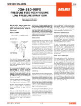
COMPACT-X AUTOMATIC GUN — AIR CAP / FLUID TIP COMBINATIONS
A Needle travel adjusting knob –
18 positions per 1 turn
B Gun head – stainless steel
C Air cap ring
D Air cap
E Air valve (fan / atom)
F Spray gun body – anodized
aluminum
G Fluid tip – stainless steel
H Manifold – stainless steel
I Manifold locking lever
J Support tightening screw
K Spray gun mounting hole –
1/2" diameter
P/R Fluid inlet, fluid return
A
F
B
C
G
D
I
J
E
ATOM FAN
K
FLUID INLET
P/R
AIR INLET
ATOM,
CYL FAN
TYPE CONVENTIONAL HVLP TRANS-TECH
AIR CAP MODEL NO. 430 443 497 500R 507 510 513 522 590 591
FLUID TIP SIZES
.020" (0.5 mm) X X
.028" (0.7 mm) X
.033" (0.85 mm) XXXXX X
.039" (1.0 mm) XXXXXXXX
.055" (1.4 mm) XXXXXXXX
.070" (1.8 mm) XXXXXXXX
.086" (2.2 mm) XXXXX
H

EN
SB-2-584-R1 (10/2020) 7 / 16 www.carlisleft.com
INSTALLATION
AIR AND FLUID HOSES
See pages 11, 13, 14 and 15 for installation details.
Use separate filtered regulated air supplies for atomizing and cylinder
air. Connect all the air and fluid hoses at the back of the manifold (1/8”
BSP): (See figure)
• Cylinder air ‘C = Cyl’ via a control valve. For fast cylinder operation
the control valve should be fitted as close to the gun as possible or
an additional quick exhaust valve installed in the line.
• Separated atomizing and fan “F” & “A” air supply.
• Material hose ‘P’. If material re-circulation is required, remove the
plug from port ‘R’ (35) and plug from spray head (34).
Recommended hose size up to 34 ft. (10 m) long:
Atomization Air = 0.315 in. (8 mm)
Cylinder Air = 0.236 in. (6 mm)
Material = 0.315 in. (8 mm)
BACK Face of Manifold
TOP Face of Manifold
SETTING
Check that the gun has all of the O-rings installed
on the sealing surface and check that the locking
device (28) is in the correct position to lock the
spray gun on to the connecting plate.
1. The ATOM ‘A’ air valve controls the atomizing air
pressure.
2. The FAN ‘F’ valve controls the spray pattern size.
3. Fluid flow is adjusted with the rear ratchet knob
(25).
For the arrangement of the parts, refer to the
exploded view on page 5.
START UP
1. Turn the needle adjusting knob (25) clockwise
until the needle is fully closed.
2. Turn the FAN ‘F’ and ATOM ‘A’ air valves (13)
counter-clockwise to be full open.
3. Use the air cap chart to set the air pressure at the
air regulator to achieve recommended pressures.
4. Turn the adjusting knob (25) counter clockwise to
obtain the desired fluid flow.
5. Test spray. If the finish is too dry or fine, reduce
the airflow by reducing the air inlet pressure or
by screwing the valve ATOM ‘A’ (13) in clockwise,
or increase the fluid flow using ratchet knob,
rotating counter clockwise.
Important: To ensure that this equipment reaches you in first class condition,
protective coatings have been used. Flush the equipment through with appropriate
solvent before use. Fix the spray gun base plate using mounting stem ref.30 and
secure it with nut ref.29.
Important: The Spray gun must be grounded to dissipate any electrostatic charges
which may be created by fluid or air flows. This can be achieved through the Spray
gun mounting, or conductive air/fluid hoses. Electrical bond from the spray gun to
earth should be checked with an ohmmeter. A resistance of less than 106 Ohms is
recommended.

EN
SB-2-584-R1 (10/2020)8 / 16www.carlisleft.com
INSTALLATION (CONTINUED)
START UP (continued)
6. If the finish is too wet, turn the ratchet knob (25)
in clockwise to reduce the fluid flow, or reduce
the fluid pressure. If the atomization is too
coarse, increase inlet air pressure, or reduce fluid
flow.
7. The pattern size can be reduced by turning
adjusting valve FAN ‘F’ (13) clockwise.
8. The spray pattern will give the best results when
perpendicular to the target.
9. The recommended spray distance is 6’’ to 8’’
(150-220 mm).
10. Spray edges first. Overlap each stroke a
minimum of 50%. Move gun at a constant
speed.
11. Always turn off air and fluid supply and relieve
pressure and clean down when gun is not in
use.
MAINTENANCE
PREVENTIVE MAINTENANCE
1. Unlock the spray gun from the base plate, remove
it, and if available re-attach an alternative gun.
Now the spray gun maintenance can be done
outside the spray booth while production is still
continuing.
2. Remove air cap (1) and clean. If any of the holes
in the cap are blocked with coating material use
a toothpick to clean. Never use metal wire which
could damage the cap and produce distorted
spray patterns
3. Ensure the nozzle of the fluid tip (2) is clean and
free from damage. Any build up of dried paint
can distort the spray pattern.
REPLACEMENT OF PARTS
TIP (2) & NEEDLE (18)
Remove the air cap (1) by unscrewing its retaining
ring counter- clockwise, remove the index ring if it
remains on the gun head (if fitted and used).
Remove the tip (2) and its air separator ring (3) by
unscrewing counter- clockwise with 10mm
hexagonal spanner.
Unscrew the adjusting needle knob (25) fully in
counter-clockwise rotation, push the needle from
the front of the spay gun, carefully so to avoid
damage the needle end, then pull out the needle
(18) from the back.
If necessary, replace the needle and the tip, first
refitting the tip with its air separator ring
(recommended torque between 9,5 to 12 Nm).
Lubricate all the surface of the needle which will be
in contact with the packing and o ring. Slide the
needle into the spray gun from the back. Fit the
needle springs with its plastic pad (22,23,24) and
replace the needle adjusting knob (25).
PACKING SEAL (9)
Unscrew the air cap (1), tip (2) and its air separator
ring (3).
Unscrew the 4 screws (6) to disassemble the gun
head (8). Push back the packing seal (9) using a
5,5mm diameter rod from the front of the gun head.
Clean the packing location hole carefully with
adequate solvent.
Fit a new packing seal (9) U face towards the fluid
passage.
Turn off air and coating supply and
relieve pressure in the supply lines,
before any maintenance operation.
Turn off air and coating supply and
relieve pressure in the supply lines, or
disconnect from airline and fluid line.

EN
SB-2-584-R1 (10/2020) 9 / 16 www.carlisleft.com
REPLACEMENT OF PARTS (CONTINUED)
FAN & ATOM AIR VALVE (13)
PISTON (15), O RING (16, 14 & 15C)
Unscrew the rear housing (19) at the back of the
gun body counter clockwise, pull out the needle
(18).
Use bent nose pliers “T” so to pull out the piston
which has a 12mm internal groove for this purpose.
Piston “P+W” and two valve “V” will pull out at
the same time. The ring “W” is located by pressing
it onto the piston body and can not be removed
from it.
The valve “V” can be removed easily from the
piston ring. We recommend to replace the full
piston at the same time (Item number SPA-60x-K).
It’s recommended to replace all the O-rings (14, 16
& 15c) in the gun body as soon you disassemble the
Piston from the gun.
Slightly lubricate the piston lip before fitting again
into the gun body. Use petroleum jelly to lubricate
the piston parts and o-rings.
Before assembling, check the air valve
is in fully open position by unscrewing
it counter-clockwise.
Piston
Assembly
(ref.)
Air Valve (ref.)
DEVILBISS SPRAY GUN TECHNOLOGY—APPLICATION DETAILS
HVLP (BLUE)
Maintains Regulatory
Compliance
The DeVilbiss "Blue" Compact
gun allows you to maintain EPA
compliance and produce a
superb finish.
Built to provide outstanding
coating atomization, the "Blue"
Compact can handle all types of
solvent and waterborne
materials.
High performance is coupled
with a gun body light in weight
and designed for operator
comfort to increase productivity.
TRANS-TECH (GREEN)
Maximum Efficiency with
Environmental Responsibility
The DeVilbiss "Green" Compact
gun utilizes the very latest
advances in computational fluid
dynamics. This results in
superior atomization with the
new DeVilbiss TRANSFER-
TECHNOLOGY.
Exceptionally efficient material
transfer for optimum coverage
and paint usage is achieved with
reduced air consumption,
lowering your electrical needs
and energy costs.
Exceed your production
requirements with the highest
atomization levels at an
accelerated application rate of up
to 600cc/min.
CONVENTIONAL (SILVER)
Outperforms the Competition
The DeVilbiss "Silver" Compact
is our Advanced Conventional
gun and has a unique high
capacity airflow with outstanding
atomization to produce a superior
result.
Compact's Advanced Conven-
tional Air Caps make this gun the
ideal performer in both small
operations or high volume
facilities, with the added bonus
of instantly improved finishing
productivity.

EN
SB-2-584-R1 (10/2020)10 / 16www.carlisleft.com
STANDARD SET-UPS AVAILABLE FOR COMPACT-X AUTOMATIC SPRAY GUN
PART NUMBER DESCRIPTION
HVLP GUNS
CMAX-B85-M COMPACT AUTO-X HVLP .85 MM W/ MANIFOLD NO CAP
CMAX-B10-M COMPACT AUTO-X HVLP 1.0 MM W/ MANIFOLD, NO AIR CAP
CMAX-B14-M COMPACT AUTO-X HVLP 1.4 MM W/ MANIFOLD, NO AIR CAP
CMAX-B18-M COMPACT AUTO-X HVLP 1.8 MM W/ MANIFOLD, NO AIR CAP
CMAX-B85PM COMPACT AUTO-X HVLP .85 MM PLASTIC NEEDLE W/ MANIFOLD, NO AIR CAP
CMAX-B14PM COMPACT AUTO-X HVLP 1.4 MM PLASTIC NEEDLE W/ MANIFOLD, NO AIR CAP
CMAX-B10-M-507 COMPACT AUTO-X HVLP 1.0 MM WITH MANIFOLD, 507 AIR CAP INCLUDED
CMAX-B14-M-507 COMPACT AUTO-X HVLP 1.4 MM WITH MANIFOLD, 507 AIR CAP INCLUDED
CMAX-B00-0 COMPACT AUTO-X HVLP NO MANIFOLD , LESS-- NOZZLE, NEEDLE, CAP
TRANS-TECH GUNS
CMAX-G05-M-590 COMPACT AUTO-X TRANS .5 MM W/ MANIFOLD, 590 AIR CAP INCLUDED
CMAX-G85-M COMPACT AUTO-X TRANS .85 MM W/ MANIFOLD, NO AIR CAP
CMAX-G10-M COMPACT AUTO-X TRANS 1.0 MM W/ MANIFOLD, NO AIR CAP
CMAX-G-14-M COMPACT AUTO-X TRANS 1.4 MM W/ MANIFOLD, NO AIR CAP
CMAX-G18-M COMPACT AUTO-X TRANS 1.8 MM W/ MANIFOLD, NO AIR CAP
CMAX-G85PM COMPACT AUTO-X TRANS .85 MM PLASTIC NEEDLE W/ MANIFOLD, NO AIR CAP
CMAX-G14PM COMPACT AUTO-X TRANS 1.4 MM PLASTIC NEEDLE W/ MANIFOLD, NO AIR CAP
CMAX-G10-M-513 COMPACT AUTO-X TRANS 1.0 MM W/ MANIFOLD, 513 AIR CAP INCLUDED
CMAX-G-14-M-513 COMPACT AUTO-X TRANS 1.4 MM W/ MANIFOLD, 513 AIR CAP INCLUDED
CMAX-G00-0 COMPACT AUTO-X TRANS NO MANIFOLD, LESS-- NOZZLE, NEEDLE, CAP
CONVENTIONAL GUNS
CMAX-10-M COMPACT AUTO-X CONV. 1.0 MM W/ MANIFOLD, NO AIR CAP
CMAX-14-M COMPACT AUTO-X CONV. 1.4 MM W/ MANIFOLD, NO AIR CAP
CMAX-18-M COMPACT AUTO-X CONV. 1.8 MM W/ MANIFOLD, NO AIR CAP
CMAX-22-M COMPACT AUTO-X CONV. 2.2 MM W/MANIFOLD, NO AIR CAP
CMAX-10-M-497 COMPACT AUTO-X CONV. 1.0 MM W/ MANIFOLD, 497 AIR CAP INCLUDED
CMAX-14-M-497 COMPACT AUTO-X CONV. 1.4 MM W/ MANIFOLD, 497 AIR CAP INCLUDED
CMAX-14PM COMPACT AUTO-X CONV. 1.4 MM PLASTIC NEEDLE W/ MANIFOLD, NO AIR CAP
CMAX-00-0 COMPACT AUTO-X CONV. NO MANIFOLD, LESS-- NOZZLE, NEEDLE, CAP
NOTE: Air caps can be ordered separately. Refer to page 8 for air cap ordering information.
COMPACT AUTOMATIC - X GUN MOUNTING ADAPTERS AND HOSE FITTING KITS:
SPK-111 CEFLA MACHINES - MOUNTING ADAPTER KIT (PAGE 14)
6-531 CEFLA MACHINES - FITTING KIT FOR AIR AND FLUID (PAGE 14)
6-534 SUPERFICII MACHINES - FITTINGS FOR AIR AND FLUID (PAGE 13)
6-533 FLUID/AIR FITTING KIT FOR NPS CONNECTIONS (PAGE 15)

EN
SB-2-584-R1 (10/2020) 11 / 16 www.carlisleft.com
REAR
VIEW
REAR
VIEW
FLUID RETURN (IF USED)
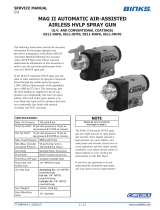
COMPACT-X AUTOMATIC GUN — TYPICAL AIR & FLUID DIAGRAMS
SEPARATE FAN & ATOMIZING AIR
(OPTIONAL GUN HOOK-UP)
BACK PRESSURE
VALVE
CYLINDER AIR SUPPLY
CYLINDER AIR
VALVE (3 WAY)
AIR REGULATOR
(FAN & ATOMIZING
AIR COMBINED)
FLUID
REGULATOR
(COMBINED)
FAN & ATOMIZING AIR SUPPLY
FLUID SUPPLY
ATOMIZING ADJUSTMENT VALVE
FAN ADJUSTMENT VALVE
ATOMIZING ADJUSTMENT VALVE
FAN ADJUSTMENT VALVE
BACK PRESSURE
VALVE
CYLINDER AIR VALVE
(3 WAY)
ATOMIZING AIR
REGULATOR
FAN AIR
REGULATOR
FLUID
REGULATOR
COMBINED FAN & ATOMIZING AIR
(STANDARD GUN HOOK-UP)
ATOMIZING ADJUSTMENT VALVE
FAN ADJUSTMENT VALVE
FLUID RETURN (IF USED)
CYLINDER AIR SUPPLY
FAN AIR SUPPLY
ATOMIZING AIR SUPPLY
FLUID SUPPLY

EN
SB-2-584-R1 (10/2020)12 / 16www.carlisleft.com
INSTALLATION DIMENSIONS for COMPACT AUTOMATIC "X" GUN
DIMENSIONS IN MM
(MULTIPLY BY .03937 TO OBTAIN INCHES)
BSPP = BRITISH STRAIGHT PIPE PARALLEL
For mounting to machine plate/bracket

EN
SB-2-584-R1 (10/2020) 13 / 16 www.carlisleft.com
6-534 SUPERFICI MACHINE FITTING KIT for COMPACT AUTOMATIC "X" GUN
8 MM O.D. TUBE (2) FLUID
CONNECTION
6 MM O.D. TUBE CONNECTION
FOR CYLINDER AIR
8 MM O.D. TUBE 2" LONG QTY. 4
(FOR ATOM / FAN / FLUID)
SUPPLIED BY CUSTOMER
1/4" BSPP (M)
CONNECTION (2)
FOR FLUID SUPPLY
AND RETURN
8 MM O.D. TUBING
CONNECTION (2) ATOM / FAN
8 MM O.D. TUBE "Y"
CONNECTION FOR COMBINED
ATOM / FAN CONNECTION
REF. SPA-111-K2 PLUG (M12-1.0)
KIT TO REPLACE MANUAL
VALVES (PURCHASE SEPARATE)
REF. 8 MM SCREW THREAD FOR
MOUNTING TO PLATE
ATTACHMENT OF THE MACHINE
NOTE: USE 1/8" BSPP PLUG (1) FOR FLUID RETURN PORT
WHEN CIRCULATING IS NOT REQUIRED.
(PLUG SUPPLIED WITH THIS KIT)
NOTE: ALL MANIFOLD AIR AND FLUID PORTS ARE 1/8" BSPP (m)
BSPP = BRITISH STRAIGHT PIPE PARALLEL
FOR MOUNTING THE SPRAY
GUN USING THE 8 MM
THREADED HOLE, SOME
MATERIAL MAY NEED TO BE
REMOVED FROM THE EDGE OF
THE SPA-111 PLUGS, AS
SHOWN.

EN
SB-2-584-R1 (10/2020)14 / 16www.carlisleft.com
6-531 CEFLA MACHINE FITTING KIT for COMPACT AUTOMATIC "X" GUN
6 MM O.D. TUBE CONNECTION
FOR CYLINDER AIR (CEFLA)
OR
4 MM O.D. TUBE CONNECTION
FOR CYLINDER AIR (FALCONI)
NOTE: ALL MANIFOLD AIR AND FLUID PORTS ARE 1/8" BSPP (m)
BSPP = BRITISH STRAIGHT PIPE PARALLEL
8 MM O.D. TUBE 2" LONG QTY. 4
FOR ATOM / FAN / FLUID
(PURCHASE SEPARATELY)
1/4" BSPP (M)
CONNECTION (2)
FOR FLUID SUPPLY
AND RETURN
8 MM O.D.
TUBE CONNECTOR (1)
FOR COMBINED
ATOM / FAN
CONNECTION
8 MM TUBE O.D. (2)
ATOM / FAN
REF: SPK-111 CEFLA MACHINE MOUNTING ADAPTER
(PURCHASE SEPARATELY)
8 MM O.D.
TUBE
CONNECTION (2)
FLUID

EN
SB-2-584-R1 (10/2020) 15 / 16 www.carlisleft.com
6-533 FITTING KIT WITH 1/4" NPS (m) for COMPACT AUTOMATIC "X" GUN
NOTE: ALL MANIFOLD AIR AND FLUID PORTS ARE 1/8" BSPP (m)
BSPP = BRITISH STRAIGHT PIPE PARALLEL
6 MM O.D. TUBE CONNECTION
FOR CYLINDER AIR
1/4" NPS (M)
CONNECTION (2)
FOR FLUID SUPPLY
AND RETURN
1/4" NPS (M) CONNECTION
(1) FOR ATOMIZING AIR
(1) FOR FAN AIR

EN
SB-2-584-R1 (10/2020)16 / 16www.carlisleft.com
WARRANTY POLICY
This product is covered by Carlisle Fluid Technologies’ materials and workmanship limited warranty.
The use of any parts or accessories, from a source other than Carlisle Fluid Technologies,
will void all warranties. Failure to reasonably follow any maintenance guidance provided
may invalidate any warranty.
For specic warranty information please contact Carlisle Fluid Technologies.
Carlisle Fluid Technologies is a global leader in innovative nishing technologies.
Carlisle Fluid Technologies reserves the right to modify equipment specications without prior notice.
BGK™, Binks®, DeVilbiss®, Hosco®, MS®, and Ransburg®
are all registered trademarks of Carlisle Fluid Technologies, Inc.
©2020 Carlisle Fluid Technologies, Inc.
All rights reserved.
For technical assistance or to locate an authorized distributor,
contact one of our international sales and customer support locations.
Region Industrial/Automotive Automotive Renishing
Americas Tel: 1-800-992-4657 Tel: 1-800-445-3988
Fax: 1-888-246-5732 Fax: 1-800-445-6643
Europe, Africa,
Middle East, India
Tel: +44 (0)1202 571 111
Fax: +44 (0)1202 573 488
China Tel: +8621-3373 0108
Fax: +8621-3373 0308
Japan Tel: +81 45 785 6421
Fax: +81 45 785 6517
Australia Tel: +61 (0) 2 8525 7555
Fax: +61 (0) 2 8525 7575
For the latest information about our products, visit www.carlisleft.com
/