Page is loading ...

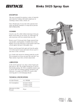
MACH 1AR AND MACH 1ARV HVLP
AUTOMATIC AIR SPRAY GUNS
(WITH RATCHET NEEDLE ADJUSTMENT)
6913-XXXX-X
MACH 1AR HVLP AUTOMATIC
AIR SPRAY GUN
Ideal for industrial coatings, the MACH 1AR HVLP “High
Volume, Low Pressure” Automatic Spray Gun
incorporates a stainless steel fluid inlet, fluid nozzle,
and fluid needle for spraying a wide variety of
conventional and waterborne coatings. It is also
pneumatically activated for application with
reciprocating, rotary, spindle machines, and in
stationary gun set-ups. The MACH 1AR Auto Gun
features a ratchet fluid needle valve adjustment where
repeatable fluid flows are required. Exceptionally
rugged in construction, this gun is built to stand up
under hard continuous use. However, like any other
fine precision instrument, it’s most efficient operation
depends on a knowledge of its construction, operation,
and maintenance.
Properly handled and cared for, it will produce
beautiful, uniform finishing results long after other
spray guns have worn out.
NOTE
IMPORTANT REGULATORY NOTE regarding the use of this product
appears on page 11.
CA PROP
65
PROP 65 WARNING
WARNING: This product contains chemicals known to the
State of California to cause cancer and birth defects or
other reproductive harm.
Servicing the spray gun while pressurized could result in
components or material exiting the spray gun at high
velocity, possibly resulting in bodily injury or damage to the
spray gun. Before removing any components from the spray
gun, shut off the air and material pressure.
!
WARNING
77-2672-R7.0 (8/2017) 1 / 16 www.carlisleft.com
EN
SERVICE MANUAL

Binks reserves the right to modify equipment specification without prior notice.
LOCK OUT / TAG-OUT
Failure to de-energize, disconnect, lock out and tag-out all power
sources before performing equipment maintenance could cause
serious injury or death.
OPERATOR TRAINING
All personnel must be trained before operating finishing
equipment.
EQUIPMENT MISUSE HAZARD
Equipment misuse can cause the equipment to rupture,
malfunction, or start unexpectedly and result in serious injury.
PROJECTILE HAZARD
You may be injured by venting liquids or gases that are released
under pressure, or flying debris.
PINCH POINT HAZARD
Moving parts can crush and cut. Pinch points are basically any
areas where there are moving parts.
INSPECT THE EQUIPMENT DAILY
Inspect the equipment for worn or broken parts on a daily basis.
Do not operate the equipment if you are uncertain about its
condition.
In this part sheet, the words WARNING, CAUTION and NOTE are used to
emphasize important safety information as follows:
Hazards or unsafe practices which
could result in minor personal injury,
product or property damage.
!
CAUTION
Hazards or unsafe practices which
could result in severe personal
injury, death or substantial property
damage.
!
WARNING
Important installation, operation or
maintenance information.
NOTE
Read the following warnings before using this equipment.
READ THE MANUAL
Before operating finishing equipment, read and understand all
safety, operation and maintenance information provided in the
operation manual.
WEAR SAFETY GLASSES
Failure to wear safety glasses with side shields could result in
serious eye injury or blindness.
NEVER MODIFY THE EQUIPMENT
Do not modify the equipment unless the manufacturer provides
written approval.
IT IS THE RESPONSIBILITY OF THE EMPLOYER TO PROVIDE THIS INFORMATION TO THE OPERATOR OF THE EQUIPMENT.
FOR FURTHER SAFETY INFORMATION REGARDING THIS EQUIPMENT, SEE THE GENERAL EQUIPMENT SAFETY BOOKLET (77-5300).
KNOW WHERE AND HOW TO SHUT OFF THE EQUIPMENT
IN CASE OF AN EMERGENCY
PRESSURE RELIEF PROCEDURE
Always follow the pressure relief procedure in the equipment
instruction manual.
NOISE HAZARD
You may be injured by loud noise. Hearing protection may be
required when using this equipment.
STATIC CHARGE
Fluid may develop a static charge that must be dissipated through
proper grounding of the equipment, objects to be sprayed and all
other electrically conductive objects in the dispensing area. Improper
grounding or sparks can cause a hazardous condition and result in
fire, explosion or electric shock and other serious injury.
PROP 65 WARNING
WARNING: This product contains chemicals known to the
State of California to cause cancer and birth defects or other
reproductive harm.
WEAR RESPIRATOR
Toxic fumes can cause serious injury or death if inhaled.
Wear a respirator as recommended by the fluid and solvent
manufacturer’s Safety Data Sheet.
TOXIC FLUID & FUMES
Hazardous fluid or toxic fumes can cause serious injury or death if
splashed in the eyes or on the skin, inhaled, injected or
swallowed. LEARN and KNOW the specific hazards or the fluids
you are using.
KEEP EQUIPMENT GUARDS IN PLACE
Do not operate the equipment if the safety devices have been
removed.
!
WARNING
AUTOMATIC EQUIPMENT
Automatic equipment may start suddenly without warning.
FIRE AND EXPLOSION HAZARD
Improper equipment grounding, poor ventilation, open flame or
sparks can cause a hazardous condition and result in fire or
explosion and serious injury.
MEDICAL ALERT
Any injury caused by high pressure liquid can be serious. If you
are injured or even suspect an injury:
• Go to an emergency room immediately.
• Tell the doctor you suspect an injection injury.
• Show the doctor this medical information or the medical alert
card provided with your airless spray equipment.
• Tell the doctor what kind of fluid you were spraying or
dispensing.
GET IMMEDIATE MEDICAL ATTENTION
To prevent contact with the fluid, please note the following:
• Never point the gun/valve at anyone or any part of the body.
• Never put hand or fingers over the spray tip.
• Never attempt to stop or deflect fluid leaks with your hand,
body, glove or rag.
• Always have the tip guard on the spray gun before spraying.
• Always ensure that the gun trigger safety operates before
spraying.
EN
77-2672-R7.0 (8/2017)2 / 16www.carlisleft.com

Cylinder
Air Inlet
1/4" NPS
Atomizing Air
Inlet 1/4" NPS
Air Supply
from Air
Compressor
Fluid Inlet
3/8" NPS
Side Port
Control Assembly
(Fan Pattern
Control)
Fluid Needle
Stroke Adjustment
Mounting
Lockscrew
Cylinder Air
Fluid
Inlet
Mounting Hole (1/2" Dia.)
Atomizing and
Fan Air Combined
Oil and Water
Extractor
Regulated Cylinder Air from Oil and Water Extractor
Regulated Fluid Inlet (From Pressure Tank or Fluid Pump)
Four Gun
Material Manifold
Four Gun
Air
Manifold
3-Way
Air Valve
or 3-Way
Solenoid Valve
For some applications, each gun may require individually regulated fluid and air inlet lines.
BINKS MACH 1AR HVLP AUTOMATIC SPRAY GUN
Typical Arrangement Diagram and Hook-Up for Combined Fan and Atomizing Air
Plastic Needle
Cover 54-4270
Combined
Fan and
Atomizing
Air
95AR
Automatic
Gun
EN
77-2672-R7.0 (8/2017) 3 / 16 www.carlisleft.com

Cylinder
Air Inlet
1/4" NPS
Fan Air Inlet
1/4" NPS
Atomizing
Air Inlet
1/4" NPS
Fluid
Inlet
3/8" NPS
Side Port
Control Assembly
(Fan Pattern
Control)
Mounting
Lockscrew
Mounting Hole (1/2" Dia.)
Atomizing
Air
Fluid
Inlet
Fan Air
Cylinder Air
Oil and Water Extractor
Regulated Cylinder Air from
Oil and Water Extractor
Regulated Fluid Inlet
Four Gun Material Manifold
Fan
Air
Atomizing Air
For some applications, each gun may require individually
regulated fluid and air inlet lines.
GENERAL NOTES:
1. Have at least 55-60 psi air pressure for cylinder’s
operating air.
2. To reduce overspray and obtain maximum
efficiency, always spray with lowest possible air
pressure that produces an acceptable spray
pattern. Fluid pressure should be less than air
pressure in most applications.
3. The air line from gun to 3-way valve should be
as short as possible for rapid operation.
4. All air used in the gun should be dirt and
moisture free. (This is accomplished by using an
oil and water extractor).
5. Shut off all fluid and air lines to gun if gun is to
stand idle for any length of time. (This is to
prevent “build-up” or accumulation of minute
leaks in the system from turning on the gun.)
BINKS MACH 1AR HVLP AUTOMATIC SPRAY GUN
Typical Arrangement Diagram and Hook-Up for Separate Fan and Atomizing Air
(See Page 5 for Internal Modifications to Gun)
3-Way
Solenoid
Four
Gun
Air
Manifold
EN
77-2672-R7.0 (8/2017)4 / 16www.carlisleft.com

TO CHANGE FROM COMBINED FAN AND ATOMIZING AIR
TO SEPARATE FAN AND ATOMIZING AIR
1. Unscrew ratchet housing assembly (28) and
remove material needle and attached parts (22,
23, 24, 25) (See assembly drawing, page 6).
Use of excessive pressure will cause the piston to exit
the gun body at high velocity, possibly resulting in
personal injury or damage to gun. When removing the
piston, point gun in a safe direction and do not use
excessive pressure.
!
WARNING
2. Remove piston assembly (18) by injecting low
pressure air cylinder air port (A).
3. With 5/32" hex key, remove plug (16) from hole
(B) on inside of cylinder.
4. Insert set screw (20-2141) into position as
shown in side cut-away. (Set screw is packaged
loose.)
5. Re-install plug (16).
6. Re-install piston (18), 2 springs (26, 27),
material needle (22), and ratchet housing
assembly (28).
(See assembly drawing, page 6).
7. Remove plug (47) from the fan air port (C).
8. Install fitting (36) into port (C). (Fitting is
packaged loose.)
Plug (47)
(remove)
Set Screw (20-2141)
Set Screw (16)
View A
Side Cut-Away Vie w A
A
C
B
B
EN
77-2672-R7.0 (8/2017) 5 / 16 www.carlisleft.com

1
2
3
4
5
6
7
8
9
10
11
12
13
14
15
16
17
18
19
20
21
22
23
24
25
26
27
28
29
30
31
32
33
34
35
36
36
37
38
39
45
46
47
48
49
50
51
52
53
54
40
41
42
43
44
Binks MACH 1AR HVLP AUTOMATIC SPRAY GUN
Typical Arrangement Diagram and Hook-Up for Combined Fan and Atomizing Air
55
EN
77-2672-R7.0 (8/2017)6 / 16www.carlisleft.com

ITEM PART
NO. NO. DESCRIPTION QTY.
ITEM PART
NO. NO. DESCRIPTION QTY.
1 54-3531 RETAINING RING ........................ 1
2
*
AIR NOZZLE ................................ 1
3
*
FLUID NOZZLE ............................ 1
4 54-3543 HEAD INSERT ............................. 1
5 54-3975 MACH 1AR GUN BODY ASS’Y. ....... 1
6 20-1359 SQ. BOLT 5/16-18 x 3/4 LG................ 1
7 54-3720 SIDE PORT CONTROL ASSEMBLY. . 1
8 54-3721 CONTROL SPINDLE ..................... 1
9 31-258 RETAINING PIN ........................... 1
10 31-256 STUFFING BOX ............................ 1
11 31-259 INNER WASHER .......................... 3
12 20-3620▲ O-RING ....................................... 1
13 31-241 CONTROL SPRING ....................... 1
14 54-4269 JAM NUT ..................................... 1
15 54-3987 PLUG .......................................... 1
16 54-3988 PLUG 1/16-27 NPT .......................... 2
17 20-5286▲ O-RING ....................................... 1
18 54-3706 PISTON ASSEMBLY ...................... 1
19 54-3729 SEAL ........................................... 1
20 54-3722 PISTON ....................................... 1
21 20-4511▲ O-RING ....................................... 2
22 47-478 NEEDLE (Stainless Steel) ................... 1
23 20-3515▲ O-RING (Needle Assembly) ................ 1
24 54-3713 NEEDLE BODY ............................. 1
25 54-3709 NEEDLE LOCKING NUT ................ 1
26 54-1697 SPRING Needle Return ..................... 1
26a 54-2143 HEAVY DUTY SPRING (Optional) ...... 1
27 54-1876 SPRING Piston Return ...................... 1
28 54-3582 RATCHET HOUSING ASSEMBLY. .... 1
29 54-3584 RATCHET HOUSING ..................... 1
30 20-2183 BALL ........................................... 2
31 54-1878 SPRING ....................................... 1
32 54-1870 INDICATOR ................................. 1
33 54-3583 SCREW ....................................... 1
34 54-1879 RATCHET .................................... 1
35 54-1984 CAP ............................................ 1
36 71-28 DOUBLE MALE NIPPLE
1/8 NPT x 1/4 NPS ........................... 2
37 54-3741 FLUID INLET Recirculating
(Optional) ..................................... 1
38 54-3533 FLUID INLET (Stainless Steel) ........... 1
39 54-4264▲
●
GLAND ADAPTER ......................... 1
40 54-4265▲
●
NEEDLE SEAL .............................. 1
41 54-4266▲
●
SEAL BACKUP .............................. 1
42 54-4267▲
●
SPRING ....................................... 1
43 54-4263▲
●
PACKING NUT ............................. 1
44 57-13 DOUBLE MALE NIPPLE
1/4 NPT x 1/4 NPS ........................... 1
45 54-3716 AIR VALVE GLAND ASSEMBLY.. ..... 1
46 20-3859▲ O-RING Air Valve Gland .................... 1
47 54-3986 PLUG 1/8-27 NPT ............................ 1
48 54-3918 WRENCH (Optional) ........................ 1
49 82-469 GUN BRUSH ................................ 1
50 54-3871 GUNNERS MATE .......................... 1
51 54-4541† FLUID INLET MACHINING ............ 1
52 20-2227▲† O-RING (2-006 BUNA-N) ................... 1
53 54-4531▲† O-RING PACKING SPACER ............ 1
54 54-4542† NUT ASSEMBLY ........................... 1
55 54-4540† FLUID INLET ASSEMBLY............... 1
54-4270 NEEDLE BOOT (Not Shown) ............. 1
54-3661 CLOTH GUN COVER (Not Shown) ..... 1
(Optional)
PARTS LIST
(When ordering, please specify Part No.)
*
See Air and Fluid Nozzle Chart.
▲ Part of Repair Kit 54-3980.
Part of Gun Body Assembly, (5).
Part of Piston Assembly (18). Also available separately.
● Part of Self-Adjusting Packing Kit (54-4261) without needle.
† Replaces Items 38-43 on vitreous setup.
3-13/16"
8-1/2" (approx.)
approx. wt. 1.5 lbs.
4"
2"
EN
77-2672-R7.0 (8/2017) 7 / 16 www.carlisleft.com

SETUP FOR SPRAYING
CONNECTING GUN TO MATERIAL HOSE
Gun should be connected by a suitable length of 3/8"
diameter material hose fitted with a connector with a
3/8" NPS(f) nut at gun end. 1/4" diameter hose is
recommended for use with low viscosity materials.
(Fluid hoses of different composition are available for
special fluids.)
CONNECTING GUN TO ATOMIZING AIR
Gun should be connected by a suitable length of 5/16"
or 3/8" diameter air hose fitted with a connector and a
1/4" NPS(f) nut at gun end.
CONNECTING GUN TO CYLINDER AIR
Gun should be connected by a suitable length of 3/16"
I.D. or 1/8" I.D. air hose of shortest length possible
with 1/4" NPS(f) connector.
OPERATING THE MACH 1AR HVLP AUTOMATIC SPRAY GUN
CONTROLLING THE MATERIAL FLOW
When fed from a pressure supply, an increase in the
material pressure will increase the rate of flow. Correct
fluid nozzle size ensures correct material flow rate. If
necessary, fluid flow can also be adjusted by adjusting
the amount of needle travel. This is done by adjusting
the ratchet housing cap (35) until the correct needle
travel is achieved.
ADJUSTING AIR AND FLUID TIMING
A 1/16" gap between the air piston assembly (18) and
needle body (24) should be maintained (see figure 1).
This will create needle motion that will allow adequate
air flow before the fluid starts flowing. The gap may be
adjusted by partially removing the material needle (22),
screwing it either in or out of the needle body (24) and
locking it back into the gun while being sure to check
the clearance between the air valve piston (18) and the
needle body (24).
ADJUSTING THE SPRAY PATTERN
The width of the spray pattern is controlled by the side
port control assembly (7). (See page 6). Turning this
control clockwise until it is closed will give a round
spray; turning it counterclockwise will widen the spray
into a fan shape. The fan spray can be turned
anywhere through 360° by positioning the air nozzle
(2) relative to the gun. To effect this: loosen retaining
ring (1); position nozzle (2) then retighten
retaining ring.
Indicator notch
Rear
View
Figure 1
1/16" clearance
20
22
23 24
25
RATCHET ADJUSTMENT
1. First, note the number on the indicator notch (see
REAR VIEW above).
2. Remove ratchet housing assembly (28) and 2 springs
(26 & 27). Make sure needle body (24) is set with a
1/16" clearance as shown in figure 1. (To set 1/16"
clearance, see “ADJUSTING AIR AND FLUID TIMING”
above).
3. Remove screw (33) from inside the center of the
ratchet housing (29) and pull off cap (35).
4. Reset cap back onto ratchet housing assembly (28)
aligning the zero on the cap to the indicator notch
as shown in the REAR VIEW above.
5. Tighten screw (33) and reassemble springs and
ratchet housing assembly to gun. The needle should
now be closed and in the zero position.
NOTE: All No’s. in parenthesis refer to Item No’s. in Assembly Drawing on Page 6.
EN
77-2672-R7.0 (8/2017)8 / 16www.carlisleft.com

NOZZLE AND NEEDLE SELECTIONS
HVLP Air Nozzles
HVLP AIR NOZZLES 95P, 97P,
95AS, 95AP, 97AP, 905P■
GUN NOZZLE NOZZLE
INLET AIR FLOW ATOMIZING
PSI SCFM PSI
20 11.0 3
30 15.7 5
38 17.5 7
45 19.6 9
50 22.5 10
HVLP AIR NOZZLE 100P■
GUN NOZZLE NOZZLE
INLET AIR FLOW ATOMIZING
PSI SCFM PSI
3.0 3.2 2
6.1 4.8 4
9.0 6.0 6
11.6 6.9 8
14.3 8.0 10
HVLP AIR NOZZLE 93P■
GUN NOZZLE NOZZLE
INLET AIR FLOW ATOMIZING
PSI SCFM PSI
8.0 5.5 3
11.5 7.0 5
14.5 8.0 7
17.0 9.5 9
18.0 10.0 10
HVLP AIR NOZZLE 90P■
GUN NOZZLE NOZZLE
INLET AIR FLOW ATOMIZING
PSI SCFM PSI
5 4.0 3
7 4.5 5
10 5.0 7
12 5.5 9
15 6.0 10
HVLP AIR NOZZLE 94P■
GUN NOZZLE NOZZLE
INLET AIR FLOW ATOMIZING
PSI SCFM PSI
14 7.0 3
21 9.0 5
27 11.0 7
30 12.0 9
33 13.0 10
FLUID NOZZLES
STANDARD NOZZLES
APPLICABLE COMPATIBLE
MATERIAL FLUID NOZZLE NO. AIR NOZZLES FLUID NEEDLE†
ULTRA LIGHT: Reduced Flow.
89 (.020" Dia.)
90P, 92P 47-478
89A (.025" Dia.)
VERY LIGHT: Reduced Flow. 90 (.030" Dia.) 93P, 94P 47-478
LIGHT: less than 15 to 20 seconds in a
91 (.040" Dia.)
95P, 97P
47-478
ZAHN 2 Cup, e.g., stains, varnishes, thin
lacquers, automotive refinishing materials.
92 (.046" Dia.)
95AP*
47-478
MEDIUM: 20 to 60 seconds in a ZAHN 2
47-478
Cup, e.g., general industrial coatings
97AP*
HEAVY: greater than 60 seconds in a
97 (.070" Dia.) 47-478
ZAHN 2 Cup.
100P
*“Blue Max” fine finish nozzles.
92P
=
For general industrial and automotive finish applications.
95P = Standard pressure nozzle for fine finish spraying.
95AP = Extra fine atomization nozzle for standard finish materials.
97P = Wide fan nozzle for fine finish of high solid coatings.
97AP = Extra fine atomization nozzle for high solids/metallics.
905P = Same as 95P but for use w/900 series fluid nozzle.
100P = Tulip Pattern shape for high quality atomization of low to medium
viscosity material.
■ NOTE: Regulator pressures are based on 25' of 5/16" diameter hose in good condition without Quick-Disconnects or other resrictive
fittings. Use the air nozzle test gauge accessory to confirm the atomizing/regulator pressure relationship for your actual air supply
set-up. These recommendations are for “typical” or “average” fluids, and are intended to serve as a starting point. Adjust as
necessary for your specific application.
94 (.055" Dia.)
95 (.059" Dia.)
96 (.063" Dia.)
HVLP AIR NOZZLE 92P■
GUN NOZZLE NOZZLE
INLET AIR FLOW ATOMIZING
PSI SCFM PSI
6.0 4.5 3
8.5 6.0 5
11.0 6.8 7
13.5 7.5 9
15.0 8.0 10
EN
77-2672-R7.0 (8/2017) 9 / 16 www.carlisleft.com

SPRAY GUN MAINTENANCE
LUBRICATION
Monthly: Remove piston assembly (18) and lubricate the
air cylinder chamber and needle valve spring with a
coating of Gunners Mate. Also, lubricate side port
control assembly (7) with oil.
Never use lubricants containing silicone since these
lubricants can cause finish defects. Binks Gunners Mate
(54-3871) is recommended.
!
CAUTION
REMOVAL OF PISTON
To remove the piston, first unscrew the ratchet housing
assembly (28), remove 2 springs (26 & 27) and pull out
the material needle and attached ports (22, 23, 24, 25).
Remove the piston by applying a few pounds of air
pressure to the cylinder air inlet. This air pressure will
cause the piston to pop out.
Use of excessive pressure will cause the piston to exit the
gun body at high velocity, possibly resulting in personal
injury or damage to gun. When removing the piston, point
gun in a safe direction and do not use excessive pressure.
!
WARNING
TO REPLACE NEEDLE SEAL AND GLAND
ADAPTER IN FLUID INLET
Remove ratchet housing assembly (28), springs (26 &
27) and material needle and attached parts consisting
of (22, 23, 24, 25).
Proceed to the front of the gun and remove retaining
ring (1), air nozzle (2) and fluid nozzle (3). Then, using
wrench (48), unscrew head insert (4) and remove fluid
inlet (37 or 38).
Unscrew packing nut (43) and remove spring (42) and
seal backup (41). Using a No. 10 x 1-1/4" coarse thread
wood screw (Binks Part No. 20-6536) or small sheet
metal screw, remove the needle seal (40) and gland
adapter (39).
Replace gland adapter (39) and needle seal (40).
Re-insert seal backup (41), spring (42) and screw on
packing nut (43) a couple of turns so it fits loosely by
hand. Reassemble fluid inlet (38) to gun body (5) with
head insert (4). Tighten head insert using wrench (48).
Reassemble fluid nozzle (3), air nozzle (2) and retaining
ring (1). Re-insert material needle and attached parts
(22, 23, 24, 25), springs (26 & 27) and screw on ratchet
housing assembly (28). Finally, tighten packing nut (43)
until it bottoms out on fluid inlet (37 or 38).
NOZZLE AND NEEDLE SELECTIONS
HVLP Air Nozzles
SPECIAL PURPOSE NOZZLES
APPLICABLE COMPATIBLE
TYPICAL APPLICATION FLUID NOZZLE NO. AIR NOZZLES FLUID NEEDLE
VERY HEAVY MATERIALS:
Block FIller, Texture Coatings,
Fire Retardants, Road Marking
Paint, Bitumastics, Adhesives,
Cellular Plastisols, Underbody
and Vitreous Coatings,
Special Applications
FEATHERING
For applications requiring
more gradual valve opening
for fluid flow control
with trigger
94VT (.052")
▲
1.3 mm 94P, 97P, 100P 54-3966
901VT (.066")
▲
1.6 mm 54-3967
903 (.079") 2.0 mm 47-478†
905 (.089") 2.3 mm 47-478†
905VT (.088")
▲
2.3 mm 905P 54-3968
906 (.100") 2.5 mm 47-478†
909 (.111") 2.8 mm 47-478†
909VT (.112")
▲
2.9 mm 54-3969
90F (.030") 0.8 mm 54-4032
91F (.040") 1.0 mm 54-4033
92F (.046") 1.2 mm
94P, 97P
54-4034
94F (.055") 1.4 mm
95AP, 97AP
54-4036
97F (.070") 1.7 mm
100P
54-4039
† Stainless steel, standard. Optional nylon tipped stainless steel (47-472).
▲
Carbide Tip – used on MACH 1AV gun.
EN
77-2672-R7.0 (8/2017)10 / 16www.carlisleft.com

SPRAY GUN CLEANING INSTRUCTIONS
In certain states it is now against the law to spray sol-
vents containing Volatile Organic Compounds (VOC)
into the atmosphere when cleaning a spray gun.
In order to comply with these new air quality laws,
Binks recommends one of the two following methods to
clean your spray finishing equipment:
1. Use an enclosed clean-up station or enclosure which
will condense and collect VOC vapors to prevent
their atmospheric release.
2. Use a washer unit. Your gun washer should com-
pletely enclose the spray gun, filter, nozzles and
other parts during wash, rinse and drain cycles to
prevent the release of VOC vapors into the atmo-
sphere.
To further protect the environment, avoid storing sol-
vents or solvent-soaked wipes, such as those used for
surface preparation and clean-up, in open or absorbent
containers.
To clean the gun, flush the fluid lines with solvent and
blow air through the air liens to make sure all the air
passages are dry.
Never completely submerge the gun in solvent as this will
dissolve the lubricating oil and dry out the seals.
!
CAUTION
TROUBLESHOOTING
FAULTY SPRAY
A faulty spray may be caused by improper cleaning,
dried materials around the fluid nozzle tip or in the
air nozzle. Soak these parts in thinners that will
soften the dried material and remove with a brush
or cloth.
Never use metal instruments to clean the air or fluid
nozzles, these parts are carefully machined and any
damage to them will cause faulty spray.
!
CAUTION
If either the air nozzle (2) or fluid nozzle (3) are
damaged, these parts must be replaced before per-
fect spray can be obtained.
FAULTY SPRAY
If the spray flutters, it is caused by one of the fol-
lowing faults:
1. Insufficient material available. Check supply and
replenish if necessary.
2. Loosen fluid nozzle (3). Tighten but without
using undue force (100-120 in. lbs. torque).
3. Leakage at gland adapter (39) and needle seal
(40). Tighten packing nut (43) if loose, and
replace gland adapter and needle seal if neces-
sary.
4. Fluid connection insufficiently tight or dirt on
cone faces of connection. Correct as necessary.
5. Leaking cylinder air and/or inadequate pressure.
6. Inadequate fluid pressure.
IMPORTANT REGULATORY NOTE
Some Regulatory Agencies prohibit the operation of HVLP spray guns above 10 psi nozzle atomizing pressure.
Users subject to this type of regulation should not exceed the gun inlet pressure indicated on the air cap and/or
in these instructions. See Air Pressure Recommendations, Pages 9 and 10 and General Spray Instructions, Page 8.
It is recommended that the nozzle test gauge shown above, be used to confirm actual nozzle operating pressure.
It may also be a requirement of some Regulatory Agencies that users have this air nozzle test gauge assembly
available on site to verify that the gun is being operated within the limits of applicable rules.
EN
77-2672-R7.0 (8/2017) 11 / 16 www.carlisleft.com

AIR NOZZLE TEST GAUGE ASSEMBLY
54-3935 for 95P, 97P, 95AP, and 97AP Nozzles.
54-3908 for 900 Series Nozzles.
54-4078 for Siphon Series Nozzles.
54-4345 for 90P Air Nozzle.
54-4356 for 93P Air Nozzle.
54-3902 for 91P and 92P Air Nozzles.
54-4066 for 94P Air Nozzle.
Part No.
59-299
Gauge Only
(Replacement)
CAUTION
Do not exceed 70 psi gun inlet pressure. Use air nozzle
test gauge assembly to determine and verify exact
nozzle operating air pressure.
!
ACCESSORIES (Optional)
MOUNTING BRACKETS
Use for automatic guns. Adjustable to any position.
18" bracket arm. One inch diameter bracket clamp hole
for attachment to facility hardware.
54-380 Steel Bracket for automatic guns.
Shipping. wt. 5 lbs. Part Sheet 1185
1/2" Dia. Gun Mounting
1" Diameter
EN
77-2672-R7.0 (8/2017)12 / 16www.carlisleft.com

NOTES
EN
77-2672-R7.0 (8/2017) 13 / 16 www.carlisleft.com

NOTES
EN
77-2672-R7.0 (8/2017)14 / 16www.carlisleft.com

NOTES
EN
77-2672-R7.0 (8/2017) 15 / 16 www.carlisleft.com

EN
77-2672-R7.0 (8/2017)16 / 16www.carlisleft.com
WARRANTY POLICY
Binks products are covered by Carlisle Fluid Technologies one year materials and workmanship
limited warranty. The use of any parts or accessories, from a source other than
Carlisle Fluid Technologies, will void all warranties. For specic warranty information please contact
the closest Carlisle Fluid Technologies location listed below.
Binks is part of Carlisle Fluid Technologies, a global leader in innovative nishing technologies.
For technical assistance or to locate an authorized distributor, contact one of our international sales
and customer support locations.
USA/Canada
Tel: 1-888-992-4657
Fax: 1-888-246-5732
United Kingdom
Tel: +44 (0)1202 571 111
Fax: +44 (0)1202 573 488
China
Tel: +8621-3373 0108
Fax: +8621-3373 0308
Mexico
Tel: +52 55 5321 2300
Fax: +52 55 5310 4790
Japan
Tel: +81 45 785 6421
Fax: +81 45 785 6517
Brazil
Tel: +55 11 5641 2776
Fax: +55 11 5641 1256
Germany
Tel: +49 (0) 6074 403 1
Fax: +49 (0) 6074 403 281
Australia
Tel: +61 (0) 2 8525 7555
Fax: +61 (0) 2 8525 7575
Carlisle Fluid Technologies reserves the right to modify equipment specications without prior notice.
DeVilbiss
®
, Ransburg
®
, ms
®
, BGK
®
, and Binks
®
are registered trademarks of Carlisle Fluid Technologies, Inc.
©2017 Carlisle Fluid Technologies, Inc.
All rights reserved.
For the latest information about our products, visit www.carlisleft.com.
/