Page is loading ...

www.TrailFX.com
Page 1 of 9 Rev R01;092021
READ INSTRUCTIONS CAREFULLY BEFORE STARTING INSTALLATION.
REMOVE CONTENTS FROM BOX. VERIFY ALL PARTS ARE PRESENT.
DO NOT OVER TORQUE. STANDARD OPERATING LOAD FOR TIGHTENING BODY
MOUNT NUTS & BOLTS IS 8 FOOT POUND FOR M6 AND 65 FOOT POUND FOR M12
ASSISTANCE IS RECOMMENDED.
PARTS LIST:
Qty
Part Description
Qty
Part Description
1
LD-1 Rear Bumper
4
12mm Plastic Retainers
2
Sensor Front Mounting Brackets
4
12-1.75mm x 40mm Hex Bolts
1
Driver/left Sensor Rear Mounting Bracket
8
12mm x 37mm x 3mm Flat Washers
1
Passenger/right Sensor Rear Mounting Bracket
4
12mm Nylon Lock Nuts
2
Plastic Sensor Covers
2
6mm x 20mm Combo Bolts
2
Flat Block-off Covers
8
6-1.0mm x 20mm Button Head Bolts
2
Plastic Plugs for License Plate
4
6-1.0mm x 20mm Hex Bolts
4
Plastic Sensor Hole Plugs
16
6mm x 18mm x 1.6mm Flat Washers
4
15.5mm x 25mm x 2mm Sensor Foam Seals
12
6mm Lock Washers
4
20mm x 10mm Foam Spacers
12
6mm Hex Nuts
4
Sensor Retaining Caps
8
4mm Self Tapping Screws
2
Wire Harness Extensions
1
4mm Wrench
1
Sensor Cover Kit
10
Plastic Wire Ties
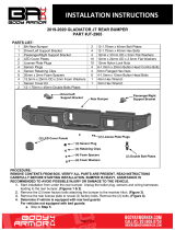
Front LD Bumper
Part No.
RLDB009TI
Fits: 2019-2021 SILVERADO 1500/ 2020-Current SILVERADO 25-3500
POWDER COATED BLACK – 3 YEARS
1- (866) 638 - 4870
support@trailfx.com
60-180 min
DRILLING NOT
REQUIRED
CUTTING NOT
REQUIRED

www.TrailFX.com
Page 2 of 9 Rev R01;092021
PROCEDURE:
REMOVE CONTENTS FROM BOX. VERIFY ALL PARTS ARE PRESENT. READ INSTRUCTIONS
CAREFULLY BEFORE STARTING INSTALLATION. BUMPER IS HEAVY, ASSISTANCE IS HIGHLY
RECOMMENDED TO AVOID POSSIBLE INJURY OR DAMAGE TO THE VEHICLE.
1. Remove the license plate and the (2) factory bolts behind the license plate, (Figures 1 & 2).
2. Unplug all wiring harnesses leading to the bumper including tire pressure monitoring system (TPMS)
and remote antenna, (Figures 2 & 3). Unplug the trailer plug, (Figure 4).
3. Place blocks or jack stands under the bumper to support it during mounting bolt removal. Assistance is
highly recommended to remove the bumper. Starting on the passenger/right side, remove the factory
bolt attaching the side of the bumper to the bumper support bracket, (Figure 5). Remove the (2) factory
flange nuts attaching the bumper to the frame, (Figure 6). Repeat this Step to remove the factory
hardware on the driver/left side. With assistance, pull bumper straight out from vehicle.
4. Move the OE rear bumper to clean and stable surface. Unplug and remove the sensors, (if equipped),
trailer plug, license lights, remote antenna with TPMS assembly bracket & the spare tire access lock
from the back of the bumper, (Figures 7—9). Remove wire harness from bumper.
5. Determine if the vehicle is equipped with parking sensors, cross traffic sensors and remote antenna:
Models without bumper parking sensors:
a. Select the included (4) Plastic Plugs.
b. Push plugs into sensor mounting holes, (Figure 10).
Models with bumper mounted parking sensors:
a. Remove the silicone seal from the end of the sensor. Slide the included Foam Washer over front of
sensor, (Figure 11).
b. Push the sensor into the back of the sensor mount. Place (1) Foam Spacer to the end of the sensor,
(Figure 12).
c. Push the Retaining Cap into the sensor mount, (Figure 12).
d. Repeat the above steps for each parking sensor.
Models with Tire Pressure Monitoring System (TPMS):
a. Select the factory remote antenna with TPMS assembly, (Figure 13).
b. Push the (3) clips on the TPMS assembly into the slots in the mounting tabs on the Bumper, (Figure
14).
Models without cross traffic sensors:
a. Select (1) Steel Block Off Plate. Attach the Plate to the back of the driver/left end of the Bumper with
(4) 6mm Button Head Bolts, (4) 6mm Flat Washers, (4) 6mm Lock Washers and (4) 6mm Hex Nuts,
(Figure 15). Repeat to install the remaining Plate on the passenger/right side of the Bumper.
Models with cross traffic alert sensors (CTA):
a. Select (1) Plastic Cover. Insert (4) 6mm Button Head Bolts through the Cover and Bumper.
b. Select (1) Front Sensor Bracket, (Figure 16). Attach the Bracket to the 6mm Bolts with (2) 6mm Flat
Washers, (2) 6mm Lock Washers and (2) 6mm Hex Nuts, (Figure 17). NOTE: Front CTA Brackets
can be installed on either left or right side of the Bumper.
c. Select the driver/left Rear Sensor Bracket. Repeat previous Step to install the Rear Sensor Bracket,
(Figure 17). IMPORTANT: Rear Sensor Brackets look similar but are unique and slightly offset.
d. Attach the Sensor to the Brackets with the included (2) 6mm x 20mm Hex Bolts, (4) 6mm Flat
Washers, (2) 6mm Lock Washers and (2) 6mm Hex Nuts, (Figures 18 & 19). IMPORTANT: Do not
overtighten hardware are damage to Plastic Cover and/or sensor may result.
e. Repeat previous Steps to attach the passenger/right Plastic Cover, Brackets and sensor.
6. Select the driver/left license plate light. Attach the license light to the mounting tab on the back of the
bumper with (1) 6mm Combo Bolt, (Figure 20). Repeat Step to install the passenger side factory license
plate light.
7. Snap the trailer plug & spare tire access lock into the openings in the Rear Bumper, (Figure 21). Insert
the (2) Plastic Plugs to attach the license plate to the Bumper, (Figure 21).
8. Plug the sensors, license lights & remote antenna with TPMS assembly back into the bumper wire
harness. Use the included (2) Wire Harness Extensions to reach the outer sensors. NOTE: Run the wire
harness over the light mounting tabs on the back of the Bumper to avoid any interference with the
exhaust. Use the included Wire Ties to secure the Harness to the Bumper.
9. LED light installation at ends of bumper (not included).
a. Insert light into opening and up to mounting slots. Check for clearance between front and back of
light. If necessary, remove the screen from the back of the opening for additional clearance or
access to light, (Figure 22).
b. Follow the light manufacturer’s instructions to attach (1) light to the center slot or (2) lights to the
inner and outer slots in the top of the light opening.
c. Repeat the above steps for passenger/right side light installation.
d. Follow light manufacturer’s instructions to properly wire the light to the electrical system.

www.TrailFX.com
Page 3 of 9 Rev R01;092021
10. Remove the bumper support brackets from the outside of the frame, (Figure 23).
11. Insert (2) 12mm Hex Bolts and (2) 12mm Flat Washers up and into the back of the mounting plate on
the driver/left side of the Bumper, (Figure 24). IMPORTANT: For 1500 models, us the outer slots in the
mounting plates, (Figure 25A). For 25-3500 models, use the inner slots in the mounting plates, (Figure
25B). Thread the (2) 12mm Plastic Retainers onto the Bolt Plate to hold it in position. Repeat to install
(2) 12mm Hex Bolts and (2) 12mm Flat Washers on the passenger/right side of the Bumper.
12. Temporarily support the weight of the Bumper. WARNING: To avoid possible injury or damage to the
vehicle, do not proceed until the Bumper is fully and safely supported.
13. With assistance, position the Bumper Assembly up to the frame. Attach the Bumper to the frame with (4)
12mm Flat Washers and (4) 12mm Nylon Lock Nuts, (Figure 26). Do not tighten hardware.
14. Level and adjust the bumper and fully tighten all hardware. Slowly open tailgate and check for
clearance. Adjust as necessary.
15. Plug the bumper wire harness & trailer plug into the vehicle harness.
16. Do periodic inspections to the installation to make sure that all hardware is secure and tight.
To protect your investment, Do not use any type of polish or wax that may contain abrasives that could damage the
finish. Mild soap may be used to clean the Bumper assembly.
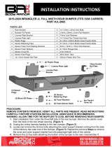
(Fig 3) Unplug all wire harnesses
leading to the Bumper
(Fig 4) Unplug the trailer plug (arrow)
(Fig 1) Remove the license
plate from the rear bumper
(Fig 2) Remove the (2) factory bolts from
behind the license plate. Release the wiring
harnesses leading to the sensor and
antenna if equipped (arrow)
Rear
Rear

www.TrailFX.com
Page 4 of 9 Rev R01;092021
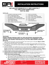
(Fig 5) Remove the bolts attaching the
outer bumper supports to the bottom of the
bumper (arrow)
(Fig 6) Remove the (2) flange nuts per
side attaching the bumper to the frame
(Fig 8) Remove the sensors, remote
antenna with TPMS assembly & spare tire
access tube from the back of the bumper.
Also remove wire harness.
Rear
(Fig 7) Remove the license plate lights,
the trailer plug and wiring harness
(Fig 9) Remove the cross traffic
sensors if equipped (arrow)
WARNING! Before removing hardware,
fully support the weight of the bumper
with blocks or stands to prevent injury
or damage to the vehicle.

www.TrailFX.com
Page 5 of 9 Rev R01;092021
Driver/left side installation pictured
(Fig 11) Models with parking sensors,
remove the silicone seal from sensor. Slide
Foam Seal over end of sensor (arrow)
Rear
Sensor
Seal
Retaining
Cap
(Fig 12) Insert sensor assembly into the
sensor sleeve. Secure with Retaining Clip.
(Fig 13) Remote antenna with TPMS assembly
(Fig 14) Attach remote antenna assembly
(Fig 13), to slots in mounting tabs
Mounting tabs for remote
antenna assembly
(Fig 10) Models without parking sensors,
insert Plastic Plugs into sensor mounts
Foam
Spacer
Rear

www.TrailFX.com
Page 6 of 9 Rev R01;092021
Driver/left side installation pictured
(Fig 15) Models without cross traffic alert
sensors (CTA), attach Block Off Plates to
Bumper
(4) 6mm x 20mm Button Head Bolts
(4) 6mm Flat Washers
(4) 6mm Lock Washers
(4) 6mm Hex Nuts
Driver/left Rear Bracket
Passenger/right
Rear Bracket
Front Brackets
(fit left or right)
Rear
Rear
(Fig 16) Select driver/left CTA Brackets
(Fig 17) Attach CTA Brackets to inside
of Bumper and Outer Plastic Cover
(Fig 18) Slide CTA sensor into Brackets
(4) 6mm x 20mm Button Head Bolts
(4) 6mm Flat Washers
(4) 6mm Lock Washers
(4) 6mm Hex Nuts

www.TrailFX.com
Page 7 of 9 Rev R01;092021
Driver/left side installation pictured
(Fig 20) Attach license plate lights to Bumper
(2) 6mm x 20mm Hex Bolts
(4) 6mm Flat Washers
(2) 6mm Lock Washers
(2) 6mm Hex Nuts
(Fig 19) Attach sensor to Brackets
Rear
6mm x 20mm
Combo Bolt
(Fig 22) Remove screens for light
clearance before installing Bumper
Rear
(2) Plastic Plugs
Trailer Plug
Tire access
(Fig 21) Insert Plastic Plugs for license plate

www.TrailFX.com
Page 8 of 9 Rev R01;092021
Driver/left side installation pictured
WARNING! Fully support the weight of
the bumper with blocks or stands to
prevent injury or damage to the vehicle.
Rear
(Fig 23) Remove the outer bumper supports
from both sides of the frame (arrow)
(2) 12mm Flat Washers
(2) 12mm Nylon Lock Nuts
(Fig 26) Attach driver/left side of Bumper
to mounts on end of frame
Rear
(Fig 24) Attach (2) 12mm Hex Bolts to the
Bumper. For 1500 models, use the outer slots.
For 2500-3500 models, use the inner slots.
(2) Plastic Retainers
(2) 12mm Hex Bolts
(2) 12mm Flat Washers
(Fig 25A) Example of 1500 models
(Fig 25B) Example of 25-3500 models
Rear
Rear
Rear

www.TrailFX.com
Page 9 of 9 Rev R01;092021
FAQ’s
1. Hardware and mounting brackets are not aligning properly
Ensure that hardware is being used on the correct side of the vehicle. In some cases, the hardware may appear same for driver or
passenger side but may alter the alignment of mounting location. Check mounting brackets for both sides.
2. Bumper is not aligning with vehicle Bumper
Brackets may be interchanged or reversed (Driver / Passenger Side). Check Brackets for each side as well ensure the proper hardware
has been used for each side.
3. Products are thumping / rattling after installation.
Ensure that all required mounting brackets / hardware’s are installed & tighten correctly. Suggest using white lithium / regular grease
between metal to metal contact.
4. Missing / Excess Hardware.
Recheck hardware count as per the part list.
5. Product not installing properly.
Ensure the Year / Make / Model as well as cab and bed dimensions are correct for the application. Review all steps for installation to
ensure they were followed correctly.
6. Who should be contacted for questions regarding product / installation assistance?
www.trailfx.com / support@trailfx.com 1-(866) 638-4870
Check out these other TrailFX Products! www.trailfx.com
PRODUCT CARE
Periodically check the product to ensure all fasteners are tight and components are intact.
Regular waxing is recommended to protect the finish of the product.
Use ONLY Non-Abrasive automotive wax. Use of any soap, polish or wax that contains an abrasive is detrimental and can scratch the
finish leading to corrosion.
Mild soap may be used to clean the Black finish product.
Keystone Automotive Operations Inc. (KAO) warrants this product to be free of defects in material and workmanship at the time of purchase by the
original retail consumer. KAO disclaims any other warranties, express or implied, including the warranty of fitness for a particular purpose or an
intended use. If the product is found to be defective, KAO may replace or repair the product at our option, when the product is returned prepaid,
with proof of purchase. Alteration to, improper installation, or misuse of this product voids the warranty. KAO’s liability is limited to repair or
replacement of products found to be defective, and specifically excludes liability for any incidental or consequential loss or damage.
/