Page is loading ...

INSTALLATION INSTRUCTIONS
Page 1 of 5
2019-2020 GLADIATOR JT BUMPER STEP (FITS JL-2965 BUMPER)
PART #JT-5100
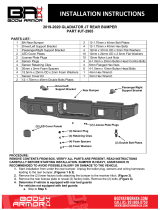
PARTS LIST:
1
Driver/Left Bed Guard
2
12mm Nylon Lock Nuts
1
Passenger/Right Bed Guard
2
10mm Double Nut Plates
1
Driver/Left Mounting Bracket
8
10mm x 40mm Hex Bolts
1
Passenger/Right Mounting Bracket
6
10mm x 30mm Hex Bolts
1
Driver/Left Support Bracket
12
10mm x 27mm OD x 2.5mm Flat Washers
1
Passenger/Right Support Bracket
8
10mm x 24mm OD x 2.2mm Flat Washers
2
14mm x 30mm OD x 65mm Spacer Tubes
8
10mm Lock Washers
2
12mm x 110mm Hex Bolts
6
10mm Nylon Lock Nuts
4
12mm x 37mm OD x 3mm Flat Washers
PROCEDURE:
REMOVE CONTENTS FROM BOX. VERIFY ALL PARTS ARE PRESENT. READ INSTRUCTIONS
CAREFULLY BEFORE STARTING INSTALLATION. BUMPER IS HEAVY, ASSISTANCE IS
RECOMMENDED TO AVOID POSSIBLE INJURY OR DAMAGE TO THE VEHICLE. CUTTING MAY BE
REQUIRED.
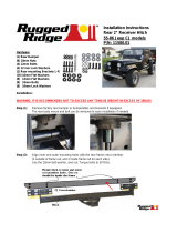
1. Start installation from under the rear bumper. Determine if the vehicle is equipped with factory bed
guards:
Models not equipped with bed guards
a. Remove the steel support bracket from the inner edge of the bumper, (Figures 1 & 2).
b. Cut the plastic pin at the top of the bumper to remove the plastic support bracket, (Figure 3).
Models equipped with bed guards
Passenger/Right
Mounting Bracket
Driver/Left
Mounting Bracket
Rear
Passenger/Right
Bed Guard
Driver/Left
Bed Guard
Driver/Left
Support Bracket
Passenger/Right
Support Bracket

INSTALLATION INSTRUCTIONS
Page 2 of 5
a. Remove the lower bolt attaching the bed guard to the hitch, (Figure 4).
b. Remove the bolts attaching the bed guard to the rear bumper, (Figure 5).
c. Remove the upper bolts attaching the bed guard to the side of the frame, (Figures 6 & 7).
IMPORTANT: The bed guard is heavy; assistance is recommended to hold the bed guards
during hardware removal to prevent injury or damage.
2. Select the Driver/left Support Bracket. Attach the Bracket to the back of the bumper with (2) 10mm x
30mm Hex Bolts, (2) 10mm Lock Washers, (2) 10mm x 24mm Flat Washers and (1) 10mm Double Nut
Plate, (Figure 8). Do not tighten hardware.
3. Attach the (2) upper holes in the Mounting Bracket to the frame with (2) 10mm x 40mm Hex Bolts, (2)
10mm Lock Washers and (2) 10mm x 27mm Lock Washers, (Figure 9). Do not tighten hardware.
4. Attach the lower hole in the Mounting Bracket to the side of the frame with (1) 12mm Hex Bolt, (2)
12mm Flat Washers, (1) 14mm Spacer Tube and (1) 12mm Nylon Lock Nut, (Figure 9). NOTE: The
Spacer Tube is required for models not equipped with a receiver hitch. Do not tighten hardware.
5. For models not equipped with bed guards
a. Hold the Bed Guard up to the mounting Bracket.
b. Place the bumper onto the vehicle to verify location before cutting. Mark the location of the Bed
Guards onto the plastic factory bumper, (Figure 10). NOTE: Use a hacksaw or sharp knife to
carefully cut the plastic bumper. Check the fit and trim as necessary.
c. Trim the bumper so the Bed Guard will fit
6. Attach the Bed Guard to the Mounting Bracket with (2) 10mm x 40mm Hex Bolts, (4) 10mm x 27mm
Flat Washers and (2) 10mm Nylon Lock Nuts, (Figure 11). Do not tighten hardware.
7. Attach the Bed Guard to the Support Bracket with (1) 10mm x 30mm Hex Bolt, (2) 10mm x 24mm Flat
Washers and (1) 10mm Nylon Lock Nut, (Figure 12). Do not tighten hardware.
8. Level and adjust the Bed Guard and tighten all hardware.
9. Repeat Steps 1—8 to attach the Passenger/Right Bed Guard.
10. Do periodic inspections to the installation to make sure that all hardware is secure and tight.
To protect your investment, Do not use any type of polish or wax that may contain abrasives that could damage the
finish. Mild soap may be used to clean the Bumper assembly.
Driver/Left Side Installation Pictured
(Fig 1) Remove the steel support bracket
from the inner edge of the bumper
(Passenger/Right side shown)
(Fig 2) Steel support bracket removed
(Passenger/Right side shown)

INSTALLATION INSTRUCTIONS
Page 3 of 5
Driver/Left Side Installation Pictured
(Fig 5) Remove the hardware attaching
the bumper to the bed guards
Rear
(Fig 4) Remove the lower bolt attaching the
bed guard (if equipped) to the receiver hitch
(Fig 6) Remove the (2) upper bolts attaching the
bed guard (if equipped) to the receiver hitch
(Fig 3) Cut the plastic pin at the top of the
bumper to remove the plastic support
bracket (Passenger/Right side shown)

INSTALLATION INSTRUCTIONS
Page 4 of 5
Driver/Left Side Installation Pictured
(Fig 7) Bed Guard mounting location
(Passenger/Right side shown)
(Fig 8) Attach the Driver/Left Support
Bracket to the back of the bumper
(2) 10mm x 30mm Hex Bolts
(2) 10mm Lock Washers
(2) 10mm x 24mm Flat Washers
10mm Double Nut Plate
12mm x 110mm Hex Bolt
(2) 12mm Flat Washers
14mm Spacer Tube
12mm Nylon Lock Nut
(2) 10mm x 40mm Hex Bolts
(2) 10mm Lock Washers
(2) 10mm x 27mm Flat Washers
(Fig 9) Attach the Drive/Left Bed Guard
assembly to the frame (NOTE: The
Spacer Tube is used when the model
is not equipped with a receiver hitch)

INSTALLATION INSTRUCTIONS
Page 5 of 5
Driver/Left Side Installation Pictured
(Fig 11) Attach the Drive/Left Bed
Guard to the Mounting Bracket
(Fig 10) Mark the cut line and cut the
bottom edge of the factory bumper
(Passenger/Right side shown)
IMPORTANT: Line up the Bed
Guard to the mounting
location. Only cut the plastic
bumper enough to allow the
Bed Guards to mount properly
(2) 10mm x 40mm Hex Bolts
(4) 10mm x 27mm Flat Washers
(2) 10mm Nylon Lock Nuts
(Fig 12) Attach the Drive/Left Bed
Guard to the Support Bracket
10mm x 30mm Hex Bolt
(2) 10mm x 24mm Flat Washers
10mm Nylon Lock Nut
/