Page is loading ...

OPERATING INSTRUCTIONS
AFS60 EtherNet/IP
AFM60 EtherNet/IP
Absolute Encoder

2
OPERATING INSTRUCTIONS | AFS60/AFM60 ETHERNET/IP 8014213/YFU7/2015-08-03 | SICK
STEGMANN Subject to change without notice
Described product
AFS60/AFM60 EtherNet/IP
Manufacturer
SICK STEGMANN GmbH
Dürrheimer Str. 36
78166 Donaueschingen
Germany
Legal information
This work is protected by copyright. Any rights derived from the copyright shall be
reserved for SICK STEGMANN GmbH. Reproduction of this document or parts of this
document is only permissible within the limits of the legal determination of Copyright
Law. Any modification, expurgation or translation of this document is prohibited without
the express written permission of SICK STEGMANN GmbH.
The trademarks stated in this document are the property of their respective owner.
© SICK STEGMANN GmbH. All rights reserved.
Original document
This document is an original document of SICK STEGMANN GmbH.

CONTENTS
OPERATING INSTRUCTIONS | AFS60/AFM60 ETHERNET/IP
3
8014213/YFU7/2015-08-03 | SICK
STEGMANN Subject to change without notice
Contents
1 About this document ................................................................................ 6
1.1 Function of this document.......................................................................... 6
1.2 Target group................................................................................................ 6
1.3 Information depth....................................................................................... 6
1.4 Scope.......................................................................................................... 7
1.5 Abbreviations used ..................................................................................... 7
1.6 Symbols used.............................................................................................. 8
2 On safety..................................................................................................... 9
2.1 Authorised personnel.................................................................................. 9
2.2 Correct use ................................................................................................. 9
2.3 General safety notes and protective measures ........................................ 10
2.4 Environmental protection ......................................................................... 10
3 Product description.................................................................................11
3.1 Special features........................................................................................ 11
3.2 Operating principle of the encoder ........................................................... 12
3.2.1 Scaleable resolution................................................................ 12
3.2.2 Preset function ........................................................................ 12
3.2.3 Round axis functionality .......................................................... 13
3.3 Integration in EtherNet/IP......................................................................... 14
3.3.1 EtherNet/IP architecture ......................................................... 14
3.3.2 EtherNet/IP communication.................................................... 15
3.4 CIP object model....................................................................................... 17
3.4.1 Supported classes................................................................... 18
3.4.2 Identity Object.......................................................................... 19
3.4.3 Assembly Object ...................................................................... 22
3.4.4 Position Sensor Object ............................................................ 28
3.5 Integration and configuration options....................................................... 36
3.5.1 Integration in EtherNet/IP ....................................................... 36
3.5.2 Configuration........................................................................... 36
3.6 Configurable functions.............................................................................. 37
3.6.1 Saving configuration and resetting.......................................... 37
3.6.2 IP address................................................................................ 40
3.6.3 Slave Sign of Life..................................................................... 40
3.6.4 Code sequence........................................................................ 40
3.6.5 Scaling..................................................................................... 40
3.6.6 Steps per revolution ................................................................ 40
3.6.7 Total resolution/measuring range........................................... 41
3.6.8 Preset function ........................................................................ 41
3.6.9 Velocity measuring unit ........................................................... 42
3.6.10 Round axis functionality .......................................................... 42
3.7 Controls and status indicators.................................................................. 43

CONTENTS
4
OPERATING INSTRUCTIONS | AFS60/AFM60 ETHERNET/IP 8014213/YFU7/2015-08-03 | SICK
STEGMANN Subject to change without notice
4 Commissioning........................................................................................44
4.1 Electrical installation................................................................................. 44
4.1.1 Connections of the AFS60/AFM60 EtherNet/IP...................... 44
4.2 Settings on the hardware.......................................................................... 45
4.2.1 Setting the IP address ............................................................. 46
4.2.2 Triggering a preset value using the preset button ................... 47
5 Configuration with the aid of a PLC......................................................48
5.1 Default delivery status.............................................................................. 48
5.2 IP address of the encoder......................................................................... 48
5.2.1 Without DHCP server ............................................................... 48
5.2.2 IP address assignment via DHCP ............................................ 48
5.2.3 Freezing the IP address assigned............................................ 50
5.2.4 Checking the integration in EtherNet/IP via
RSLinx-Classic.......................................................................... 50
5.3 Creating a project in the controller software............................................. 50
5.4 Integration of the encoder as a generic module....................................... 53
5.4.1 Module settings....................................................................... 54
5.4.2 Download the configuration to the control system.................. 55
5.4.3 Checking the communication.................................................. 56
5.5 Integration and configuration with the aid of an EDS file ......................... 56
5.5.1 Prerequisites ........................................................................... 56
5.5.2 Establishing communication ................................................... 56
5.5.3 Configuration........................................................................... 59
5.6 Installation of the ladder routine .............................................................. 59
5.6.1 Importing the ladder routine.................................................... 61
5.6.2 Integrating in the MainRoutine as a SubRoutine..................... 66
5.6.3 Using the SubRoutine.............................................................. 67
5.6.4 Reading and changing the parameters of the encoder ........... 68
5.7 Function block .......................................................................................... 71
5.7.1 Prerequisites ........................................................................... 71
5.7.2 Importing and connecting........................................................ 71
5.8 Program examples.................................................................................... 71
5.8.1 Reading temperature .............................................................. 72
5.8.2 Setting preset value................................................................. 79
6 Configuration with the aid of the integrated web server ..................87
6.1 Home ........................................................................................................ 88
6.1.1 Device...................................................................................... 88
6.1.2 Position.................................................................................... 88
6.1.3 Velocity .................................................................................... 88
6.1.4 Temperature............................................................................ 88
6.1.5 Timer ....................................................................................... 89

CONTENTS
OPERATING INSTRUCTIONS | AFS60/AFM60 ETHERNET/IP
5
8014213/YFU7/2015-08-03 | SICK
STEGMANN Subject to change without notice
6.2 Parameterization ...................................................................................... 89
6.2.1 Overview.................................................................................. 90
6.2.2 Units ........................................................................................ 91
6.2.3 Triggering preset...................................................................... 91
6.2.4 Scaling..................................................................................... 92
6.2.5 Round axis functionality .......................................................... 93
6.2.6 Changing preset value............................................................. 93
6.2.7 Limits....................................................................................... 94
6.2.8 Reset ....................................................................................... 94
6.3 Diagnostics ............................................................................................... 95
6.3.1 Status...................................................................................... 95
6.3.2 Velocity .................................................................................... 96
6.3.3 Temperature............................................................................ 96
6.3.4 Time......................................................................................... 96
6.3.5 Cycles ...................................................................................... 96
6.3.6 Heartbeat ................................................................................ 96
6.4 Tools ......................................................................................................... 97
6.4.1 EDS.......................................................................................... 97
6.4.2 Ladder routine......................................................................... 97
6.4.3 Update..................................................................................... 97
6.4.4 Address switches..................................................................... 98
6.4.5 Fault header information......................................................... 98
6.5 Test notes ................................................................................................. 99
7 Fault diagnosis...................................................................................... 100
7.1 In the event of faults or errors ................................................................ 100
7.2 SICK STEGMANN support .......................................................................100
7.3 Diagnostics ............................................................................................. 100
7.3.1 Error and status indications on the LEDs .............................. 100
7.3.2 Self-test via EtherNet/IP........................................................102
7.3.3 Warnings, alarms and errors via EtherNet/IP........................ 102
7.3.4 Error messages from the Allen-Bradley control system.........105
8 Annex ..................................................................................................... 107
8.1 EU declaration of conformity................................................................... 107
9 List of figures ........................................................................................ 108
10 List of tables.......................................................................................... 112

1 ABOUT THIS DOCUMENT
6
OPERATING INSTRUCTIONS | AFS60/AFM60 ETHERNET/IP 8014213/YFU7/2015-08-03 | SICK
STEGMANN Subject to change without notice
1 About this document
Please read this chapter carefully before working with this documentation and the
AFS60/AFM60 EtherNet/IP Absolute Encoder.
1.1 Function of this document
These operating instructions are designed to address the technical personnel of the
machine manufacturer or the machine operator in regards to correct configuration,
electrical installation, commissioning, operation and maintenance of the
AFS60/AFM60 EtherNet/IP Absolute Encoder.
1.2 Target group
The operating instructions are addressed at the planners, developers and operators of
systems in which one or more AFS60/AFM60 EtherNet/IP Absolute Encoders are to be
integrated. They also address people who initialize the use of the
AFS60/AFM60 EtherNet/IP or who are in charge of servicing and maintaining the
device.
These instructions are written for trained persons who are responsible for the instal-
lation, mounting and operation of the AFS60/AFM60 EtherNet/IP in an industrial
environment.
1.3 Information depth
These operating instructions contain information on the AFS60/AFM60 EtherNet/IP
Absolute Encoder on the following subjects:
product features
electrical installation
commissioning and configuration
fault diagnosis and troubleshooting
conformity
These operating instructions do not contain any information on the mounting of the
AFS60/AFM60 EtherNet/IP. You will find this information in the mounting instructions
included with the device.
They also do not contain any information on technical specifications, dimensional
drawings, ordering information or accessories. You will find this information in the data
sheet for the AFS60/AFM60 EtherNet/IP.
Planning and using measurement systems such as the AFS60/AFM60 EtherNet/IP also
requires specific technical skills beyond the information in the operating instructions
and mounting instructions. The information required to acquire these specific skills is
not contained in this document.
When operating the AFS60/AFM60 EtherNet/IP, the national, local and statutory rules
and regulations must be observed.
Further information
www.odva.org

ABOUT THIS DOCUMENT 1
OPERATING INSTRUCTIONS | AFS60/AFM60 ETHERNET/IP
7
8014213/YFU7/2015-08-03 | SICK
STEGMANN Subject to change without notice
1.4 Scope
NOTE
These operating instructions apply to the AFS60/AFM60 EtherNet/IP Absolute Encoder
with the following type codes:
Singleturn encoder = AFS60A-xxIx262144
Multiturn encoder = AFM60A-xxIx018x12
1.5 Abbreviations used
Common Industrial Protocol
Counts per Measuring Range
Customized Number of Revolutions, Divisor = divisor of the customized number of
revolutions
Customized Number of Revolutions, Nominator = dominator of the customized number
of revolutions
Counts Per Revolution
Dynamic Host Control Protocol
Device Level Ring
EtherNet/IP adapter developers kit = development environment for EtherNet/IP
devices
Electronic Data Sheet
Electrically Erasable Programmable Read-only Memory
Field Programmable Gate Array = electronic component that can be programmed to
provide an application-specific circuit
Input and Output Data (from the point of view of the master)
Industrial Protocol
Internet Protocol
Media Access Control
Open DeviceNet Vendor Association
Programmable Logic Controller
Transmission Control Protocol
User Datagram Protocol = connectionless network protocol
CIP
CMR
CNR_D
CNR_N
CPR
DHCP
DLR
EADK
EDS
EEPROM
FPGA
I/O
IP in EtherNet/IP
IP in TCP/IP
MAC
ODVA
PLC
TCP
UDP

1 ABOUT THIS DOCUMENT
8
OPERATING INSTRUCTIONS | AFS60/AFM60 ETHERNET/IP 8014213/YFU7/2015-08-03 | SICK
STEGMANN Subject to change without notice
1.6 Symbols used
NOTE
Refer to notes for special features of the device.
LED symbols describe the state of a diagnostics LED. Examples:
O The LED is illuminated constantly.
Ö The LED is flashing.
o The LED is off.
Instructions for taking action are shown by an arrow. Read carefully and follow the
instructions for action.
WARNING
Warning!
A warning indicates an actual or potential risk or health hazard. They are designed to
help you to prevent accidents.
Read carefully and follow the warning notices.
O, Ö, o
► Take action …

ON SAFETY 2
OPERATING INSTRUCTIONS | AFS60/AFM60 ETHERNET/IP
9
8014213/YFU7/2015-08-03 | SICK
STEGMANN Subject to change without notice
2 On safety
This chapter deals with your own safety and the safety of the equipment operators.
b Please read this chapter carefully before working with the
AFS60/AFM60 EtherNet/IP or with the machine or system in which the
AFS60/AFM60 EtherNet/IP is used.
2.1 Authorised personnel
The AFS60/AFM60 EtherNet/IP Absolute Encoder must only be installed, commis-
sioned and serviced by authorized personnel.
NOTE
Repairs to the AFS60/AFM60 EtherNet/IP
are only allowed to be undertaken by trained
and authorized service personnel from SICK STEGMANN GmbH.
The following qualifications are necessary for the various tasks:
Activity Qualification
Mounting
Basic technical training
Knowledge of the current safety regulations in the
workplace
Electrical installation and
replacement
Practical electrical training
Knowledge of current electrical safety regulations
Knowledge on the use and operation of devices in the
related application (e.g. industrial robots, storage and
conveyor technology)
Commissioning, operation
and configuration
Knowledge on the current safety regulations and the use
and operation of devices in the related application
Knowledge of automation systems (e.g. Rockwell
ControlLogix Controller)
Knowledge of EtherNet/IP
Knowledge of the usage of automation software (e.g.
Rockwell RSLogix)
Table 1: Authorised personnel
2.2 Correct use
The AFS60/AFM60 EtherNet/IP Absolute Encoder is a measuring device that is manu-
factured in accordance with recognized industrial regulations and meets the quality
requirements as per ISO 9001:2008 as well as those of an environment management
system as per ISO 14001:2009.
An encoder is a device for mounting that cannot be used independent of its foreseen
function. For this reason an encoder is not equipped with immediate safe devices.
Considerations for the safety of personnel and systems must be provided by the con-
structor of the system as per statutory regulations.
Due to its design, the AFS60/AFM60 EtherNet/IP can only be operated within an
EtherNet/IP network. It is necessary to comply with the EtherNet/IP specifications and
guidelines for setting up an EtherNet/IP network.
In case of any other usage or modifications to the AFS60/AFM60 EtherNet/IP, e.g.
opening the housing during mounting and electrical installation, or in case of modifica-
tions to the SICK software, any claims against SICK STEGMANN GmbH under warranty
will be rendered void.

2 ON SAFETY
10
OPERATING INSTRUCTIONS | AFS60/AFM60 ETHERNET/IP 8014213/YFU7/2015-08-03 | SICK
STEGMANN Subject to change without notice
2.3 General safety notes and protective measures
WARNING
Please observe the following procedures in order to ensure the correct and safe use
of the AFS60/AFM60 EtherNet/IP!
The encoder is to be installed and maintained by trained and qualified personnel with
knowledge of electronics, precision mechanics and control system programming. It is
necessary to comply with the related standards covering the technical safety stipula-
tions.
The safety regulations are to be met by all persons who are installing, operating or
maintaining the devices:
The operating instructions must always be available and must always be followed.
Unqualified personnel are not allowed to be present in the vicinity of the system
during installation and maintenance.
The system is to be installed in accordance with all applicable safety regulations
and the mounting instructions.
All work safety regulations of the applicable countries are to be followed during
installation.
Failure to follow all applicable health and safety regulations may result in injury or
damage to the system.
The current and voltage sources in the encoder are designed in accordance with
all applicable technical regulations.
2.4 Environmental protection
Please note the following information on disposal.
Assembly Material Disposal
Packaging Cardboard Waste paper
Shaft Stainless steel Scrap metal
Flange Aluminium Scrap metal
Housing Aluminium die cast Scrap metal
Electronic assemblies Various Electronic waste
Table 2: Disposal of the assemblies

PRODUCT DESCRIPTION 3
OPERATING INSTRUCTIONS | AFS60/AFM60 ETHERNET/IP
11
8014213/YFU7/2015-08-03 | SICK
STEGMANN Subject to change without notice
3 Product description
This chapter provides information on the special features and properties of the
AFS60/AFM60 EtherNet/IP. Absolute EncoderIt describes the construction and the
operating principle of the device.
b Please read this chapter before mounting, installing and commissioning the
device.
NOTE
SICK uses standard IP technology in its products. The focus is on the availability of the
products and services. SICK always assumes that the integrity and confidentiality of
data and the rights related to the usage of the aforementioned products will be ad-
dressed by the customer. In any case suitable security measures, e.g. network separa-
tion, firewalls, anti-virus protection, patch management etc. are always to be implemen-
ted by the customer to suit the situation.
3.1 Special features
Properties
Singleturn encoder
Multiturn encoder
Absolute Encoder in 60 mm design
C C
Robust nickel coded disk for harsh environments
C C
High precision and reliability
C C
Large ball bearing spacing of 30 mm
C C
High level of resistance to vibration
C C
Optimal rotational accuracy
C C
Compact design
C C
Face mount flange, servo flange and blind hollow
shaft
C C
18 bit singleturn resolution
(1 to 262,144 steps)
C C
30 bit total resolution
C
12 bit multiturn resolution
(1 to 4,096 revolutions)
C
Round axis functionality
C
EtherNet/IP interface (according to IEC 61784-1)
C C
Supports the encoder profile 22h defined in the CIP
(Common Industrial Protocol)
C C
Device Level Ring (DLR)
C C
Table 3: Special features of the encoder variants

3 PRODUCT DESCRIPTION
12
OPERATING INSTRUCTIONS | AFS60/AFM60 ETHERNET/IP 8014213/YFU7/2015-08-03 | SICK
STEGMANN Subject to change without notice
3.2 Operating principle of the encoder
The AFS60/AFM60 EtherNet/IP acquires the position and velocity of rotating axes and
outputs the position in the form of a unique digital numeric value. Optical acquisition of
the rotary position value is from an internal coded disk.
The AFS60 EtherNet/IP is a singleturn encoder
Singleturn encoders are used if the absolute position of the shaft for one revolution is
required.
The AFM60 EtherNet/IP is a multiturn encoder
Multiturn encoders are used if more than one shaft revolution must be acquired
absolutely.
3.2.1 Scaleable resolution
The steps per revolution and the total resolution can be scaled and adapted to the
related application.
The steps per revolution can be scaled from 1 … 262,144 as an integer. The total
resolution of the AFM60 EtherNet/IP must be 2ⁿ times the steps per revolution. This
restriction is not relevant if the round axis functionality is activated.
3.2.2 Preset function
The position value for an encoder can be set with the aid of a preset value. I.e. the
encoder can be set to any position within the measuring range. In this way, e.g., the
encoder’s zero position can be adjusted to the machine’s zero point.
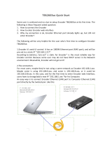
Figure 1: Setting a preset value
1 = Setting a preset value
2 = On switching back on
On switching off the encoder, the offset, the delta between the real position value and
the value defined by the preset, is saved. On switching back on the new preset value is
formed from the new real position value and the offset. Even if the position of encoder
changes while it is switched off, this procedure ensures the correct position value is
still output.
2
1
Actual position
value
Po
sition value
after preset
Offset
Position value after
switching back on
Offset

PRODUCT DESCRIPTION 3
OPERATING INSTRUCTIONS | AFS60/AFM60 ETHERNET/IP
13
8014213/YFU7/2015-08-03 | SICK
STEGMANN Subject to change without notice
3.2.3 Round axis functionality
The encoder supports the function for round axes. During this process, the steps per
revolution are set as a fraction (see section 3.6.10 on page 42). As a result, the total
resolution does not have to be configured to 2ⁿ times the steps per revolution and can
also be a decimal number (e.g. 12.5).
NOTE
The output position value is adjusted with the zero point correction, the code sequence
set and the gearbox parameters entered.
Example with transmission ratio
A rotary table for a filling system is to be controlled. The steps per revolution are pre-
defined by the number of filling stations. There are nine filling stations. For the precise
measurement of the distance between two filling stations, 1000 steps are required.
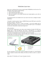
Figure 2: Example position measurement on a rotary table with transmission ratio
The number of revolutions is pre-defined by the transmission ratio = 12.5 of the rotary
table gearing.
The total resolution is then 9 × 1000 = 9000 steps, to be realized in 12.5 revolutions
of the encoder. This ratio cannot be realized via the steps per revolution and the total
resolution, as the total resolution is not 2ⁿ times the steps per revolution.
The application problem can be solved using the round axis functionality. Here the
steps per revolution are ignored. The total resolution as well as the nominator and
divisor for the number of revolutions are configured.
9000 steps are configured as the total resolution.
For the nominator for the number of revolutions 125 is configured, 10 as the divisor
(
125
/10 = 12.5).
After 12.5 revolutions (that is after one complete revolution of the rotary table) the
encoder reaches the total resolution of 9000.
125
10
Rotary table with nine filling stations
Encoder

3 PRODUCT DESCRIPTION
14
OPERATING INSTRUCTIONS | AFS60/AFM60 ETHERNET/IP 8014213/YFU7/2015-08-03 | SICK
STEGMANN Subject to change without notice
Example without transmission ratio
Figure 3: Example position measurement on a rotary table without transmission ratio
The encoder is mounted directly on the rotary table. The transmission ratio is 1:1.
The rotary table has 9 filling stations. The encoder must be configured such that it
starts to count with 0 at one filling station and counts to 999 on moving to the next
filling station position.
1000 steps are configured as the total resolution.
For the nominator for the number of revolutions 1 is configured, 9 as the divisor
(
1
/9 revolutions = 1000).
After
1
/9 revolutions of the encoder shaft there are 1000 steps, then the encoder starts
to count at 0 again.
3.3 Integration in EtherNet/IP
3.3.1 EtherNet/IP architecture
EtherNet/IP and therefore also the AFS60/AFM60 EtherNet/IP use Ethernet for the
transmission technology.
The network components are generally integrated into a star or line topology.
Figure 4: Example of an EtherNet/IP network in a star topology.
1000 steps
Rotary table with nine filling stations
Encoder
Encoder
Encoder
Switch
PLC
HMI

PRODUCT DESCRIPTION 3
OPERATING INSTRUCTIONS | AFS60/AFM60 ETHERNET/IP
15
8014213/YFU7/2015-08-03 | SICK
STEGMANN Subject to change without notice
The system can also be integrated in a Device Level Ring (DLR) in order to achieve a
higher reliability and less wiring effort.
Figure 5: Example of an EtherNet/IP network in a Device Level Ring
The AFS60/AFM60 EtherNet/IP supports Device Level Ring.
3.3.2 EtherNet/IP communication
MAC address
Each AFS60/AFM60 EtherNet/IP has a factory-assigned worldwide unique MAC
address for device identification. It is used for the identification of the Ethernet node.
This 6 byte device identification can not be changed and comprises the following
components:
3 bytes manufacturer ID
3 bytes device ID
TCP/IP and UDP/IP
EtherNet/IP uses TCP/IP or UDP/IP for the communication.
For identification the IP address is required. A fixed address is assigned to the encoder
using the address switches or the address is obtained from a DHCP server.
If the IP address is configured fix, only the least significant byte can be configured.
192.168.1.xxx is preset permanently.
Additionally the subnet mask (default = 255.255.255.0) and if required a gateway
must be configured in the network.
For real-time communication between the controller and the encoder in EtherNet/IP
Implicit messaging is used. With implicit messaging, a connection is established bet-
ween two devices within the CIP to transfer, e.g., I/O data such as position, velocity etc.
from the encoder to the controller (see also section 3.4.4 “Position Sensor Object” on
page 28). Implicit messaging uses UDP/IP via port 2222. As a result a fast data rate is
used.
Explicit messaging is used in EtherNet/IP for communication that does not need to
take place in real time. Explicit messaging uses TCP/IP, it is used e.g. to transfer para-
meters from the controller to the encoder (see also section 3.4.3 “Assembly Object” on
page 22).
Encoder
Encode
r
PLC
HMI

3 PRODUCT DESCRIPTION
16
OPERATING INSTRUCTIONS | AFS60/AFM60 ETHERNET/IP 8014213/YFU7/2015-08-03 | SICK
STEGMANN Subject to change without notice
Common Industrial Protocol (CIP)
EtherNet/IP uses the CIP on the process layer. Similarly as e.g. FTP is used for the
transfer of files, this protocol is used for process control.
Figure 6: CIP and other services
The AFS60/AFM60 EtherNet/IP meets the requirements of the EtherNet/IP protocol
according to IEC 61784-1 and those of the encoder profile 22h.
The encoder is an I/O adapter in the EtherNet/IP. It receives and sends explicit mes-
sages and implicit messages either cyclic or on request (polled).
EtherNet/IP communication
EtherNet/IP is based on the standard Ethernet FRAME. This contains the Ethernet
header, the Ethernet data and the Ethernet trailer. The MAC addresses of the receiver
(destination address) and of the source (source address) are contained in the Ethernet
header.
Figure 7: Ethernet FRAME
Process layer
Communication layers
Physical layer
Explicit Messaging
Implicit Messaging
Header
Transmission sequence
Data Field
Trailer
46 … 1500 Byte

PRODUCT DESCRIPTION 3
OPERATING INSTRUCTIONS | AFS60/AFM60 ETHERNET/IP
17
8014213/YFU7/2015-08-03 | SICK
STEGMANN Subject to change without notice
The Ethernet data field consists of several nested protocols:
The IP datagram is transported in the user data of the Ethernet data field.
The TCP segment or the UDP datagram are transported in the user data of the IP
datagram.
The CIP protocol is transported in the user data of the TCP segment or of the UDP
datagram.
Figure 8: Ethernet data field
3.4 CIP object model
EtherNet/IP uses a so-called object model for network communication wherein all
functions and data of a device are defined.
The most important terms are as follows:
A class contains related objects of a device, organized in instances.
An instance consists of different attributes that describe the properties of this instance.
Different instances of a class have the same services and the same attributes. They
can, however, have different attribute values.
The attributes represent the data a device provides over EtherNet/IP. These include the
current values of, for example, a configuration or an input. Typical attributes are confi-
guration or status information.
Services are used to access classes or the attributes of a class or to generate specific
events. These services execute defined actions such as the reading of attributes.
Class Instance Attribute Value
Code 23h 1h 0Ah 3FFFFFFFh
Designation
Position Sensor
Object
Class has one
instance
Current position
value
Example
Table 4: Example CIP object model
Class
Instance
Attribute
Service
IP header
CIP header
IP datagram
TCP segment or UDP datagram
CIP protocol
TCP/UDP
header
CIP data

3 PRODUCT DESCRIPTION
18
OPERATING INSTRUCTIONS | AFS60/AFM60 ETHERNET/IP 8014213/YFU7/2015-08-03 | SICK
STEGMANN Subject to change without notice
3.4.1 Supported classes
The AFS60/AFM60 EtherNet/IP supports the following classes of the 22h encoder
profile:
Figure 9: Supported classes
Class code Class Description Access Instances
01h Identity Object
Includes all device specific data (e.g.
ID, device type, device status etc.)
Get 1
02h
Message
Router Object
Includes all supported class codes of
the encoder and the maximum num-
ber of connections
Get 1
04h
Assembly
Object
Assembles the data of several ob-
jects to one single object. Supplies
(for example) the position value of
the encoder
Get 7
06h
Connection
Manager
Object
Includes connection specific attri-
butes for triggering, transport,
connection type etc.
Get 1
23h
Position
Sensor Object
Includes all attributes for the pro-
gramming of the encoder parame-
ters such as the scaling
Set/Get
1
F4h Port Object
Includes the available ports, port
name and node address
Get 1
F5h
TCP/IP
Interface
Object
Includes the attributes for TCP/IP
such as IP address, subnet mask
and gateway or acquisition of the
IP address via DHCP or hardware
switches
Set/Get
1
01h Identity
F4h
06h Connection Manager
04h Assembly
23h Position Sensor
F5h
F6h
Network
02h
Message
Router
48h QoS
47h DLR

PRODUCT DESCRIPTION 3
OPERATING INSTRUCTIONS | AFS60/AFM60 ETHERNET/IP
19
8014213/YFU7/2015-08-03 | SICK
STEGMANN Subject to change without notice
Class code Class Description Access Instances
F6h
Ethernet link
object
Includes connection specific
attributes such as transmission
speed, interface status and the MAC
address
Get 3
47h
Device Level
Ring (DLR)
Object
Includes status attributes and
configuration attributes of the DLR
protocol
Get 1
48h
Quality of
Service (QoS)
Object
Contains mechanisms for processing
data streams with different priorities
Get 1
Table 5: Supported classes
3.4.2 Identity Object
The device information and device parameters are opened via the instances.
Figure 10: Connections for the Identity Object
Service code Service Description
01h Get_Attribute_All Returns the values of all attributes
0Eh Get_Attribute_Single Returns the values of one attribute
Table 6: Class services of the Identity Object
01h Identity
F4h
06h Connection Manager
04h Assembly
23h Position Sensor
F5h
F6h
Network
0
2h
Message
Router
48h QoS
47h DLR

3 PRODUCT DESCRIPTION
20
OPERATING INSTRUCTIONS | AFS60/AFM60 ETHERNET/IP 8014213/YFU7/2015-08-03 | SICK
STEGMANN Subject to change without notice
Attribute ID Access Description Data type Default value
1 Get Object revision index UINT 0001h
2 Get
Highest instance number
within this class
UINT 0001h
3 Get
Number of object instances in
this class
UINT 0001h
4 Get Optional attribute list STRUCT –
6 Get
Highest existing class attribute
ID
UINT 0007h
7 Get
Highest implemented instance
attribute
UINT 0075h
Table 7: Class attributes of the Identity Object
NOTE
Class attribute 5 is not implemented.
Service code Service Description
01h Get_Attribute_All Returns the values of all attributes
0Eh Get_Attribute_Single Returns the values of one attribute
05h Reset Resets the device:
0 = The device is re-initialized (power on).
1 = The device is re-initialized (power on) and reset
to the factory settings.
Table 8: Instance Services of the Identity Object
Attribute
ID
Access Name Description Data type Default value
01h Get Vendor ID Manufacturer ID
0328h = SICK
UINT 0328h
02h Get
Device
Type
Device profile
22h = Encoder
UINT 0022h
03h Get
Product
Code
Vendor specific product code
03h = Singleturn
04h = Multiturn
UINT
04h Get Revision
Contains the firmware revi-
sion number in the format
XX.XX
STRUCT
Get
Major
Revision
First part of the revision
number, e.g. 01
(depending on the release)
UINT 01h
Get
Minor
Revision
Last part of the revision
number, e.g. 02
(depending on the release)
UINT 02h
05h Get Status Device status flags WORD See Table 10
/