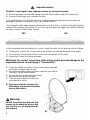
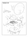
Teleco Telesat 65 - 85 is an advanced satellite TV reception system designed to provide users with an exceptional viewing experience on the go. With its compact and portable design, the Telesat 65 - 85 is perfect for caravans, motorhomes, and boats, allowing you to enjoy your favorite TV channels and programs even when you're away from home. The system's high-gain dish and powerful LNB ensure a strong and stable signal, even in remote areas or under challenging weather conditions.
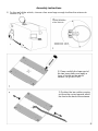
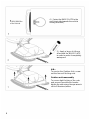
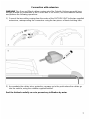
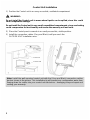
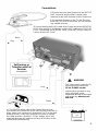
Setting up the Telesat 65 - 85 is a breeze, thanks to its user-friendly design and clear instructions.
Teleco Telesat 65 - 85 is an advanced satellite TV reception system designed to provide users with an exceptional viewing experience on the go. With its compact and portable design, the Telesat 65 - 85 is perfect for caravans, motorhomes, and boats, allowing you to enjoy your favorite TV channels and programs even when you're away from home. The system's high-gain dish and powerful LNB ensure a strong and stable signal, even in remote areas or under challenging weather conditions.
Setting up the Telesat 65 - 85 is a breeze, thanks to its user-friendly design and clear instructions.


-
 1
1
-
 2
2
-
 3
3
-
 4
4
-
 5
5
-
 6
6
-
 7
7
-
 8
8
-
 9
9
-
 10
10
-
 11
11
-
 12
12
-
 13
13
-
 14
14
-
 15
15
-
 16
16
-
 17
17
-
 18
18
-
 19
19
-
 20
20
-
 21
21
-
 22
22
-
 23
23
-
 24
24
-
 25
25
-
 26
26
-
 27
27
-
 28
28


Teleco Telesat 65 - 85 is an advanced satellite TV reception system designed to provide users with an exceptional viewing experience on the go. With its compact and portable design, the Telesat 65 - 85 is perfect for caravans, motorhomes, and boats, allowing you to enjoy your favorite TV channels and programs even when you're away from home. The system's high-gain dish and powerful LNB ensure a strong and stable signal, even in remote areas or under challenging weather conditions.
Setting up the Telesat 65 - 85 is a breeze, thanks to its user-friendly design and clear instructions.
Ask a question and I''ll find the answer in the document
Finding information in a document is now easier with AI
Related papers
-
Teleco Telesat pannello verticale User manual
-
-
-
-
Teleco Flatsat Easy BT User manual
-
Teleco Flatsat Light (digital) User manual
-
-
-
-
Other documents
-
 Mecatronic ASR 680 DF Installation and Use Manual
-
 Playcraft Sport Bank Shot 40" Pool Table Assembly Manual
-
Displays2go IMU60DC Assembly Instructions
-
Winegard TRAV'LER RP-SK41 User manual
-
Home Decorators Collection 7633810340 Operating instructions
-
Home Decorators Collection 7634310340 Operating instructions
-
 MotoSAT MD1000.2 User manual
-
Trust 17362 Datasheet
-
 CEL-MAR ADA-13110 User manual
-
idh by St. Simons 13200-008 Installation guide


