Page is loading ...

MB900-R
Socket LGA775 Pentium
®
4
Intel
®
945G Chipset
Industrial Motherboard
USER’S MANUAL
Version 1.0

Acknowledgments
Award is a registered trademark of Award Software International,
Inc.
PS/2 is a trademark of International Business Machines
Corporation.
Intel and Pentium 4 are registered trademarks of Intel Corporation.
Microsoft Windows is a registered trademark of Microsoft
Corporation.
Winbond is a registered trademark of Winbond Electronics
Corporation.
All other product names or trademarks are properties of their
respective owners.

MB900-R User’s Manual iii
Table of Contents
Introduction
....................................................... 1
Checklist ..............................................................................1
MB900-R Specifications .....................................................2
Board Dimensions ................................ ............................... 3
Installations
....................................................... 4
Installing the CPU ............................................................... 5
ATX Power Installation .......................................................6
Installing the Memory .........................................................6
Setting the Jumpers .............................................................7
Connectors on MB900-R...................................................11
Watchdog Timer Configuration ........................................20
BIOS Setup
....................................................... 25
Drivers Installation
...................................... 47
Intel 945G Chipset Software Installation Utility ...............48
Intel 945G Chipset Graphics Driver ..................................50
Realtek Codec Audio Driver Installation ..........................51
Marvell 88E8052 LAN Drivers Installation ......................52
Intel PRO LAN Drivers Installation ................................ ............53
Appendix
........................................................... 55
A. I/O Port Address Map ...................................................55
B. Interrupt Request Lines (IRQ) ......................................56

iv MB900-R User’s Manual
This page is intentionally left blank.

INTRODUCTION
MB900-R User’s Manual 1
Introduction
Checklist
Your MB900-R Pentium
®
4 motherboard package should include the
items listed below:
The MB900-R motherboard
This User’s manual
1 Back I/O shield
1 IDE cable
1 Floppy cable
1 SATA cable
1 Serial-Port cable
1 CD containing the following:
Chipset Drivers
Flash Memory Utility

INSTALLATIONS
2 MB900-R User’s Manual
MB900-R Specifications
Form Factor
Micro-ATX / 244mm x 244mm
CPU Type
Intel Pentium D (dual core) / Pentium 4 / Celeron D
CPU Voltage
0.8375V~1.6V (VRD 10.1)
System Speed
3.8GHz
CPU FSB
533/800/1066MHz
Green /APM
APM1.2
CPU Socket
Socket 775
Cache
256K/1M/2M Level 2 (CPU integrated)
Chipset
Intel 945G Chipset
GMCH: 945G, 1202-pin FCBGA
ICH: ICH7 652-pin mBGA; FWH
BIOS
Award BIOS Support ACPI Function
Memory
2x DDRII 533/667 DIMM Modules (w/o ECC), Max. 2GB
(Dual Channels)
VGA
945G built-in, support CRT
LAN
1. ICH7 LAN controller (10/100Mb) + PHY 82562ET
2. Marvel 88E8052 PCI-Exp Gigabit LAN controller x1
USB
ICH7 built-in USB 2.0 host controller, supports 8 ports
SATA II
ICH7 built-in Serial ATA II controller (300MB/s), 2 ports
Parallel IDE
ICH7 built-in one channel Ultra DMA 33/66/100, IDE1
40-pin, 2.5mm; Compact Flash Socket x1 on IDE1
Audio
ICH7 Built-in Audio controller + AC 97 Codec ALC880 8
Channel (Line-out, Line-in & Mic.), D-Sub connector
LPC I/O
Winbond W83627EHG: Parallel x1, FDC 1.44MB, COM1
(RS232), COM2 (RS232/422/485), Hardware monitor (3
thermal inputs, 4 voltage monitor inputs, VID0 -4 & 3 Fan
headers). Not use IrDA
2
nd
LPC I/O
Fintek F81216, supports COM3, 4 (RS232)
Expansion Slots
PCI Express x16 slot x1
PCI Express x1 slot x1
PCI slot x2
Edge Connectors
PS/2 KB/Mouse, LPT, VGA, COM1, Dual triple DIN for
high definition audio, RJ45, USB x4
On Board Headers
/ Connectors
USB x 4, SATA x2, IDE1, FDD, COM2/3/4, IrDA, audio
(line out / Mic)
Power Connector
ATX 12V (24 pin + 8 pin)
System Voltage
+5V, +3.3V, +12V, -12V & 5VSB (2A)
Other
Modem Wakeup & LAN Wakeup
Watchdog Timer
Yes (256 segments: 0, 1, 2…, 255 s ec/min)
Digital I/O
4 In / 4 Out
BIOS Function
-
Power on after power fail
-
Boot from USBCDROM/USBZIP/USBHDD/USB/HDD
& PXE boot
-
Supports PC health monitoring for CPU, power supply,
Aux temperatures and voltages. Supports CPU
overheating protection
Remarks:
MB900-R supports both Pentium® D dual core CPU and
Pentium® 4 single core CPU. It also supports EMT64 processors.

INTRODUCTION
MB900-R User’s Manual 3
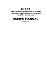
Board Dimensions

INSTALLATIONS
4 MB900-R User’s Manual
Installations
This section provides information o n how to use the jumpers and
connectors on the MB900 -R in order to set up a workable system. The
topics covered are:
Installing the CPU ................................................................ ........ 5
ATX Power Installation ............................................................... 6
Installing the Memory ................................ ................................ .. 6
Setting the Jumpers ................................ ................................ ...... 7
Connectors on MB900 -R ................................ ........................... 11
Watchdog Timer Configuration ................................ ................. 20

INSTALLATIONS
MB900-R User’s Manual 5
Installing the CPU
The MB900-R motherboard supports a n LGA 775 processor socket for
Intel® Pentium® 4 processors.
The LGA 775 processor socket comes with a lever to secure the
processor. Refer to the pictures below, from left to right, on how to place
the processor into the CPU socket.
Please note that the cover o f the
LGA775 socket must always be installed during transport to avoid
damage to the socket.

INSTALLATIONS
6 MB900-R User’s Manual
ATX Power Installation
The system power is provided to the motherboard with the ATX1 and
ATX_12V power connectors. ATX1 is a 24-pin power connector and
ATX_12V is a 8-pin 12V power connector.
The 24-pin power connector can to be connected to a standard 20-pin
ATX power connector in a standard ATX power supply (Min. 400watt).
Note: The power supply 5VSB voltage must be at least 2A .
Installing the Memory
The MB900-R motherboard supports two DDR2 memory sockets for a
maximum total memory of 2GB in DDR memory type. It supports DDR2
533/667.
Basically, the system memory interface has the following features:
Supports two 64-bit wide DDR data channels
Available bandwidth up to 5.3GB/s (DDR2 667) for single -channel
mode and 10.7GB/s (DDR2 667) in dual -channel mode.
Supports 256Mb, 512Mb, 1Gb DDR2 technologies.
Supports only x8, x16, DDR2 devices with four banks
Supports only unbuffere d DIMMs
Supports opportunistic refresh
Up to 32 simultaneously open pages (four per row, four rows
maximum)

INSTALLATIONS
MB900-R User’s Manual 7
Setting the Jumpers
Jumpers are used on MB900 -R to select various settings and features
according to your needs and applications. Contact your su pplier if you
have doubts about the best configuration for your needs. The following
lists the connectors on MB900 -R and their respective functions.
Jumper Locations on MB900 -R ................................ ......................8
JP1, JP2, JP3: RS232/422/485 (COM2) Selection ..........................9
JP4: IDE DMA Mode Setting .........................................................9
JP6: Clear CMOS Contents .............................................................9
JP7: CF Socket Master / Slave Selection .......................................10

INSTALLATIONS
8 MB900-R User’s Manual
Jumper Locations on MB900 -R
JP1, JP2, JP3: RS232/422/485 (COM2) Selection ................................ 9
JP4: IDE DMA Mode Setting ................................ ................................ 9
JP6: Clear CMOS Contents ................................ ................................... 9
JP7: CF Socket Master / Sla ve Selection ................................ ............. 10

INSTALLATIONS
MB900-R User’s Manual 9
JP1, JP2, JP3: RS232/422/485 (COM2) Selection
COM1 is fixed for RS-232 use only.
COM2 is selectable for RS232, RS -422 and RS-485. COM3 and COM4
are fixed for RS-232 use only. The following table describes th e jumper
settings for COM2 selection.
COM2
Function
RS-232
RS-422
RS-485
Jumper
Setting
(pin closed)
JP1:
1-2
JP2:
3-5 & 4-6
JP3:
3-5 & 4-6
JP1:
3-4
JP2:
1-3 & 2-4
JP3:
1-3 & 2-4
JP1:
5-6
JP2:
1-3 & 2-4
JP3:
1-3 & 2-4
JP4: IDE DMA Mode Setting
JP4
Setting
Function
Pin 1-2
Short/Closed
UDMA66 (default)
Pin 2-3
Short/Closed
Forced UDMA33
JP6: Clear CMOS Contents
Use JP6, a 3-pin header, to clear the CMOS contents. Note that the
ATX-power connector should be disconnected from the motherboard
before clearing CMOS.
JP6
Setting
Function
Pin 1-2
Short/Closed
Normal
Pin 2-3
Short/Closed
Clear CMOS

INSTALLATIONS
10 MB900-R User’s Manual
JP7: CF Socket Master / Slave Selection
JP7
CF Mode
Slave
Master

INSTALLATIONS
MB900-R User’s Manual 11
[
Connectors on MB900 -R
The connectors on MB900 -R allows you to connect external devices such
as keyboard, floppy disk drives, hard disk drives, printers, etc. The
following table lists the connectors o n MB900-R and their respective
functions.
ATX1: 24-pin ATX Power Connector .................................................13
ATX2: ATX 12V Power Connector .....................................................13
MB900-R Edge Connectors ................................ ................................ .13
CN1: PS/2 Keyboard and PS/2 Mouse Connectors .............................. 14
CN2, J2, J7, J8: COM1/2/3/4 Serial Ports ............................................14
CN3: Parallel Port Connector ................................ ............................... 15
CN4: VGA CRT Connector ................................................................ .15
CN5: Audio Connector................................ ................................ .........16
CN6: 10/100 RJ-45 and USB0/1 Connector ................................ .........16
CN7: GbE RJ-45 and USB2/3 Connector ................................ ............16
CN11, CN10: SATA0/1 Connector ......................................................16
J1: Digital I/O Connector (4 in, 4 out) ................................ ..................17
J3: Audio Front Header ................................ ................................ ........17
J5: USB4/USB5 Connector ................................................................ ..17
J6: USB6/USB7 Connector ................................................................ ..17
J9: Wake On LAN Connecto r .............................................................. 18
J10: System Function Connector ................................ ..........................18
J11: IrDA Connector ................................................................ ............18
FAN1: CPU Fan Power Connector ......................................................18
FAN2, FAN3, FAN4: Fan Power Connectors ......................................19
IDE1: Primary IDE Connectors ................................ ............................ 19
PCIE_1: x16 PCI Express Slot ................................ ............................. 19
PCIE_2: x1 PCI Express Slot ............................................................... 19
PCI1, PCI5: PCI Slots ..........................................................................19
CN12: CF Socket................................................................ ..................19
J12: SMBus ................................................................ ..........................19

INSTALLATIONS
12 MB900-R User’s Manual
Connector Locations on MB900 -R
ATX1: 24-pin ATX Power Connector ................................................................ ............................................ 13
ATX2: ATX 12V Power Connector ................................................................ ............................................... 13
MB900-R Edge Connectors ................................ ........................................................................................... 13
CN1: PS/2 Keyboard and PS/2 Mouse Connectors ................................................................ ......................... 14
CN2, J2, J7, J8: COM1/2/3/4 Serial Ports ................................................................................................ ...... 14
CN3: Parallel Port Connector ................................ ......................................................................................... 15
CN4: VGA CRT Connector ................................................................ ........................................................... 15
CN5: Audio Connector ................................ ................................................................................................ .. 16
CN6: 10/100 RJ-45 and USB0/1 Connector ................................ ................................ ................................... 16
CN7: GbE RJ-45 and USB2/3 Connector ................................ ....................................................................... 16
CN11, CN10: SATA0/1 Connector ................................ ................................................................................ 16
J1: Digital I/O Connector (4 in, 4 out) ................................ ............................................................................ 17
J3: Audio Front Header ................................ ................................ .................................................................. 17
J5: USB4/USB5 Connector ................................................................................................ ............................ 17
J6: USB6/USB7 Connector ................................................................ ............................................................ 17
J9: Wake On LAN Connector ................................ ................................ ........................................................ 18
J10: System Function Connector ................................................................................................ .................... 18
J11: IrDA Connector ................................................................ ...................................................................... 18
FAN1: CPU Fan Power Connector ................................................................ ............................................... 18
FAN2, FAN3, FAN4: Fan Power Connectors ................................................................................................ 19
IDE1: Primary IDE Connectors ................................ ...................................................................................... 19
PCIE_1: x16 PCI Express Slot ................................................................ ................................ ....................... 19
PCIE_2: x1 PCI Express Slot ................................ ......................................................................................... 19
PCI1, PCI5: PCI Slots ................................................................ .................................................................... 19
CN12: CF Socket ................................................................................................ ........................................... 19
J12: SMBus ................................................................ ................................................................................... 19

INSTALLATIONS
MB900-R User’s Manual 13
ATX1: 24-pin ATX Power Connector
Signal Name
Pin #
Pin #
Signal Name
3.3V
13
1
3.3V
-12V
14
2
3.3V
Ground
15
3
Ground
PS-ON
16
4
+5V
Ground
17
5
Ground
Ground
18
6
+5V
Ground
19
7
Ground
-5V
20
8
Power good
+5V
21
9
5VSB
+5V
22
10
+12V
+5V
23
11
+12V
Ground
24
12
+3.3V
ATX2: ATX 12V Power Connector
Signal Name
Pin #
Pin #
Signal Name
+12V
5
1
Ground
+12V
6
2
Ground
+12V
7
3
Ground
+12V
8
4
Ground
MB900-R Edge Connectors

INSTALLATIONS
14 MB900-R User’s Manual
CN1: PS/2 Keyboard and PS/2 Mouse Connectors
Keyboard
Signal
Pin #
Mouse
Signal
Keyboard data
1
Mouse data
N.C.
2
N.C.
GND
3
GND
5V
4
5V
Keyboard clock
5
Mouse clock
Mouse (top)
Keyboard (bottom)
N.C.
6
N.C.
CN2, J2, J7, J8: COM1/2/3/4 Serial Ports
CN2 (COM1) is a DB-9 connector, while J2, J7 and J8 are a COM
pin-header connectors.
COM1 COM2
Signal Name
Pin #
Pin #
Signal Name
DCD, Data carrier detect
1
6
DSR, Data set ready
RXD, Receive data
2
7
RTS, Request to send
TXD, Transmit data
3
8
CTS, Clear to send
DTR, Data terminal ready
4
9
RI, Ring indicator
GND, ground
5
10
Not Used
COM2 is jumper selectable for RS -232, RS-422 and RS-485.
Pin #
Signal Name
RS-232
R2-422
RS-485
1
DCD
TX-
DATA-
2
RX
TX+
DATA+
3
TX
RX+
NC
4
DTR
RX-
NC
5
Ground
Ground
Ground
6
DSR
RTS-
NC
7
RTS
RTS+
NC
8
CTS
CTS+
NC
9
RI
CTS-
NC
10
NC
NC
NC

INSTALLATIONS
MB900-R User’s Manual 15
CN3: Parallel Port Connector
CN3 is a DB-25 external connector situated on top of the VGA and serial
ports.
CN4 Parallel Port
Signal Name
Pin #
Pin #
Signal Name
Line printer strobe
1
14
AutoFeed
PD0, parallel data 0
2
15
Error
PD1, parallel data 1
3
16
Initialize
PD2, parallel data 2
4
17
Select
PD3, parallel data 3
5
18
Ground
PD4, parallel data 4
6
19
Ground
PD5, parallel data 5
7
20
Ground
PD6, parallel data 6
8
21
Ground
PD7, parallel data 7
9
22
Ground
ACK, acknowledge
10
23
Ground
Busy
11
24
Ground
Paper empty
12
25
Ground
Select
13
N/A
N/A
CN4: VGA CRT Connector
CN4 is a DB-15 VGA connector located beside the COM1 port. The
following table shows the pin -out assignments of this connector.
Signal Name
Pin #
Pin #
Signal Name
Red
1
2
Green
Blue
3
4
N.C.
GND
5
6
GND
GND
7
8
GND
VCC
9
10
GND
N.C.
11
12
DDCDATA
HSYNC
13
14
VSYNC
DDCCLK
15

INSTALLATIONS
16 MB900-R User’s Manual
CN5: Audio Connector
CN6: 10/100 RJ-45 and USB0/1 Connector
CN7: GbE RJ-45 and USB2/3 Connector
CN11, CN10: SATA0/1 Connector
Pin #
Signal Name
1
Ground
2
TX+
3
TX-
4
Ground
5
RX-
6
RX+
7
Ground
/