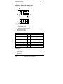
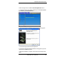
GLOBAL AMICI Computer Hardware 2807700 User manual
- Category
- Motherboards
- Type
- User manual

User’s Manual
2807700
Version 1.0

Copyrights
This manual is copyrighted and all rights are reserved. It does not
allow any non authorization in copied, photocopied, translated or
reproduced to any electronic or machine readable form in whole or in part
without prior written consent from the manufacturer.
In general, the manufacturer will not be liable for any direct, indirect,
special, incidental or consequential damages arising from the use of
inability to use the product or documentation, even if advised of the
possibility of such damages. The manufacturer keeps the rights in the
subject to change the contents of this manual without prior notices in order
to improve the function design, performance, quality and reliability. The
author assumes no responsibility for any errors or omissions, which
may appear in this manual, nor does it make a commitment to update the
information contained herein.
Trademarks
Intel is a registered trademark of Intel Corporation.
Award is a registered trademark of Award Software, Inc.
All other trademarks, products and or product's name mentioned
herein are mentioned for identification purposes only, and may be
trademarks and/or registered trademarks of their respective companies or
owners.
ii 2807700 User’s Manual

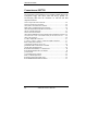
Table of Contents
Introduction.......................................................1
Checklist..............................................................................1
Product Description.............................................................2
Specifications......................................................................3
Boar d Dimensions............... ......... ............... ...................... ..4
Installations. ........................ ..............................5
Installing the CPU...............................................................6
ATX Power Installation ......................................................6
Installing the Memory .........................................................7
Setting the Jumpers .............................................................8
Connectors on 2807700.......................................................12
BIOS Setup.......................................................23
Drivers Installation......................................45
Intel Q965 Chipset Software Installation Utility...............46
Intel Q965 Chipset Gr aphics Driver..................................48
Realtek Codec Audio Driver Installation .......................... 50
Intel LAN Drivers Installation ..........................................51
Appendix...........................................................55
A. I/O Port Address Map................................................... 55
B. Interrupt Request Lines (IRQ) ......................................56
C. Watchdog T imer Confi guration....................................57
Contact Information ..................................62
2807700 User’s Manual iii

This page is intentionally left blank.
iv 2807700 User’s Manual

INTRODUCTION
Introduction
Checklist
Your 2807700 Core 2 Duo motherboard package should include the
items listed below:
•
The 2807700 motherboard
•
This User’s manual
•
1 x I/O shield
•
1 x IDE cable
•
1 x SATA cable
•
1 CD containing the following:
•
Chipset Drivers
•
Flash Memory Utility
2807700 User’s Manual 1

INSTALLATIONS
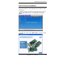
Product Description
The 2807700 Mini-ITX motherboard is designed for either the
Intel
®
Core
™
2 Duo or Intel
®
Pentium
®
D processors of up to
1066MHz FSB. It is based on the Intel’s Q965 Express chipset
and it comes with two single-channel DDR2 memory slots and
4GB memory capacity for faster system responsiveness and
support of 64-bit computing. The new Global American, Inc
motherboards are aimed for high performance PCs in the digital,
communications and industrial sector.
On board is one PCI Express x16 slot that offers up to 3.5X the
bandwidth over traditional PCI architecture to support the latest
high-performance graphics cards. Dual independent display
comes to life with the onboard Intel
®
Q965 integrated graphics for
CRT and an optional SDVO card supporting either an LVDS or
DVI display interface. LAN functionality is supported with a 10/100
Ethernet controller or with two Gigabit Ethernet controllers.
2807700 is expandable for 8x2 pins pin header for adaptor card
ID394 that support 2 or 4 serial ports, or ID395 that support TPM
1.2 for security function. Other useful features on the board
include four SATA II ports, six USB 2.0 interface, watchdog timer,
digital I/O and two serial ports. Board dimensions are 170mm by
170mm. (Note: CPU power consumption – under 95watt
recommended.)
2807700 FEATURES
• Intel
®
Q965 Express Chipset Based
• Support LGA775 Intel
®
Core
™
2 Duo Processors
• Support FSB 1066/800/533MHz
• Support up to 4GB DDRII 800/667/533 memory
• 1 x PCI Express(x16)
• Support one 10/100 or two Gigabit LAN on board
• 4 x SATA II, 1 x IDE, 6 x USB 2.0, 2 x COM,
• 7.1Ch.HD Audio
2 2807700 User’s Manual

INTRODUCTION
Specifications
Processor
Supports Intel Core 2 Du o proces sor (Conroe core) in LG A775 socket
FSB
533/800/1066 MHz
Chipset
Intel Q9 65 Chipset con sisting of:
•
Intel Q965 Graphic Memory Cont roller Hub (GM CH)
•
Intel ICH8 I/O Controller Hub
BIOS
•
Award BIOS: SPI interface only, supports ACPI, SM BIOS
Memory
•
Two 240-pin DDRII 533/ 667/800 DIM M sockets (2x single ch)
•
Supports max. 4 GB system memory
Video
Int el Q9 65 integrated graphic subsystem (GMA3000), dual ind epende nt
display avai labl e t hrough on-board V GA a nd P CI-e x 16 expa nsion
adapter (DVI or LVDS) or VGA card
LAN
LAN1: d ual Footprint sup port option:
•
Intel 82566DC Nineveh 10/100/1000 LAN
•
Int el 8256 2V Ekron- N 10/100
LAN 2: Marv ell 88E80 53 PCI-express Gigabit LAN controller x1
USB
Intel ICH8 built-in USB 2.0 host controller, supports 6 ports:
•
4 ports in the rear I/O region
•
2 ports with on-b oard headers
SATA II
Intel ICH8 built-in SATA II controller (3.0Gb/sec) w/ 4 ports
IDE
JMicron JMB368 (PCI-e to PATA) x1 for 1 PATA channel
Audio
Intel ICH8 built-in high definition a udio w/ Re altek ALC 888 Codec
LPC I/O
Winbond W83627EHF: COM1 (RS232), COM2 (RS232/422/485) &
Hardware monitor
Edge
Connectors
On Board
Headers /
Connectors
•
Mini-DIN for PS/2 KB & MS, DB9 connector for COM1, DB15
connector for VGA, RJ45 + dual USB stack connector x2 for
LAN1~2 and US B1 ~4, Trip le (3x1) audio phone jack stack conn ector
•
S ATA (7-pi n shrou ded vertical) con nector x4, US B 5-6, C OM2
(RS232/422/485), Digital I/O, 7.1 channel audio, I DE, CPU fan &
s yste m fan head ers
Expansion
PCI-express (x16) sl ot x1
8x2 pins pin-header x1 for adaptor card:
- ID394 (2 or 4 serial ports - Fintek F81216)
- ID 395 (TPM1.2 – Winbond WPCT200/ATMEL AT97SC3203
co-layout)
RTC
ICH8 built-in RT C with on-board lithium bat ter y
Watchdog
Tim er
Yes (256 seg ments, 0, 1, 2…255 sec/min)
Digit al IO
4 in and 4 Out
Other
LAN Wa keup
Power
Connector
System
Voltage
24 pins ATX main power + 4 pins 12V
CPU Power: 95W max.
+5V, +3.3V, +12V, -12V & 5VSB
Bo ard Siz e
170 x 170mm
2807700 User’s Manual 3

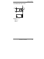
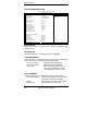
INSTALLATIONS
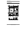
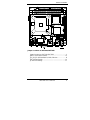
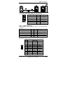
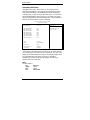
Board Dimensions
4 2807700 User’s Manual

INSTALLATIONS
Installations
This section provides information on how to use the jumpers and
connectors on the 2807700 in order to set up a workable system.
The topics covered are:
Installing the CPU ........................................................................ 6
ATX Power Installation ............................................................... 6
Installing the Memory .................................................................. 7
Setting the Jumpers ...................................................................... 8
Connectors on 2807700 .............................................................. 12
2807700 User’s Manual 5

INSTALLATIONS
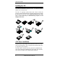
Installing the CPU
The 2807700 motherboard supports an LGA 775 processor socket for
Intel® Core 2 Duo processors.
The LGA 775 processor socket comes with a lever to secure the
processor. Refer to the pictures below, from left to right, on how to place
the processor into the CPU socket. Please note that the cover of the
LGA775 socket must always be installed during transport to avoid
damage to the socket.
ATX Power Installation
The system power is provided to the motherboard with the ATX1 and
ATX2 power connectors. ATX1 is a 24-pin power connector and ATX2
is a 4-pin 12V power connector.
The 24-pin power connector can to be connected to a standard 20-pin
ATX power connector in a standard ATX power supply (Min. 400watt).
Note: The power supply 5VSB voltage must be at least 2A.
6 2807700 User’s Manual

INSTALLATIONS
Installing the Memory
The 2807700 motherboard supports four DDR2 memory sockets for
a maximum total memory of 4GB in DDR memory type. It
supports DDR2 533/667/800.
Basically, the system memory interface has the following features:
Supports two 64-bit wide DDR data channels
Available bandwidth up to 6.4GB/s (DDR2 800) for single-channel
mode.
Supports 256Mb, 512Mb, 1Gb DDR2 technologies.
Supports only x8, x16, DDR2 devices with four banks
Supports only unbuffered DIMMs
Supports opportunistic refresh
Up to 32 simultaneously open pages (four per row, four rows
maximum)
2807700 User’s Manual 7

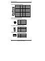
INSTALLATIONS
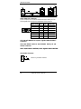
Setting the Jumpers
Jumpers are used on the motherboard are used to select various settings
and features according to your needs and applications. Contact your
supplier if you have doubts about the best configuration for your needs.
The following lists the connectors and their respective functions.
Jumper Locations on 2807700A/2807700B.................................... 9
JBAT1: Clear CMOS Contents..................................................... 10
JP1, JP2, JP3: RS232/422/485 (COM2) Selection ....................... 10
JP6: Processor Setting................................................................... 10
J6: Power ON Setting ................................................................... 11
8 2807700 User’s Manual

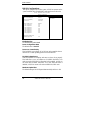
INSTALLATIONS
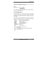
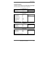
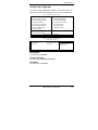
Jumper Locations on 2807700A/2807700B
Jumper Locations on 2807700A/2807700B ................................... 9
JBAT1: Clear CMOS Contents .................................................... 10
JP1, JP2, JP3: RS232/422/485 (COM2) Selection ....................... 10
JP6: Processor Setting .................................................................. 10
J6: Power ON Setting ................................................................... 11
2807700 User’s Manual 9

INSTALLATIONS
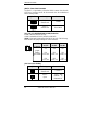
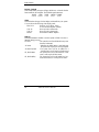
JBAT1: Clear CMOS Contents
Use JBAT1, a 3-pin header, to clear the CMOS contents. Note that the
ATX-power connector should be disconnected from the motherboard
before clearing CMOS.
JBAT1 Setting Function
Pin 1-2
Short/Closed
Normal
Pin 2-3
Short/Closed
Clear CMOS
JP1, JP2, JP3: RS232/422/485 (COM2) Selection
COM1 is fixed for RS-232 use only.
COM2 is selectable for RS232, RS-422 and RS-485.
ID394: COM3 and COM4 are fixed for RS-232 use only. The following
table describes the jumper settings for COM2 selection.
COM2
Function
RS-232 RS-422 RS-485
Jumper
Setting
(pin closed)
JP3:
1-2
JP1:
3-5 & 4-6
JP2:
3-5 & 4-6
JP3:
3-4
JP1:
1-3 & 2-4
JP2:
1-3 & 2-4
JP3:
5-6
JP1:
1-3 & 2-4
JP2:
1-3 & 2-4
JP6: Processor Setting
JP6 Setting Processor Used
Pin 1-2
Short/Closed
Celeron D
Pin 1-2
Open
Core 2 Duo,
Pentium D,
Pentium 4 HT
10 2807700 User’s Manual

INSTALLATIONS
J6: Power ON Setting
J6 Setting Function
Pin 1-2
Short/Closed
Power on by system
button
Pin 2-3
Short/Closed
Power on by power
supply AC on
2807700 User’s Manual 11

INSTALLATIONS
Connectors on 2807700
The connectors on 2807700 allows you to connect external devices such
as keyboard, floppy disk drives, hard disk drives, printers, etc.
The following table lists the connectors on 2807700 and their
respective functions.
ATX1: 24-pin ATX Power Connector..............................................................14
ATX2: ATX 12V Power Connector .................................................................14
CPU_FAN1: CPU Fan Power Connector ........................................................14
PWR_FAN1: SYSTEM Fan Power Connectors...............................................14
CN2: PS/2 Keyboard and PS/2 Mouse Connectors ..........................................15
CN1 J3: COM1/2 Serial Ports ..........................................................................15
VGA1: VGA CRT Connector ..........................................................................16
CN3: Marvell 88E8053 PCI-express Gigabit LAN and USB6/7 Connector ...16
CN6: Intel 8256 2V 1 0/100 or Intel 8256 6DC GbE RJ-45 and USB 4/5 Conne ctor
. ........16
CN4: Audio Connector .....................................................................................16
F_USB1: USB0/USB1 Connector ....................................................................17
S_ATA1, S_ATA2, S_ATA3, S_ATA4: SATA HDD Connectors ..................17
IDE1: Primary IDE Connectors........................................................................17
J2: Digital I/O Connector (4 in, 4 out)..............................................................18
J4: External Audio Connector for 7.1 channel .................................................18
JP4: For LPC I/F Adaptor Card ........................................................................18
ID394 with Fintek F81216, 2 or 4 Serial Ports .................................................18
ID395 Winbond WPCT200 x1 for TPM1.2 .....................................................18
J5: Power LED .................................................................................................18
J7: System Function Connector ........................................................................19
PCIE_1: x16 PCI Express Slot .........................................................................19
ID394 LPC Serial Ports Adaptor Card .............................................................20
ID395 WINBOND WPCT200 for TPM1.2 ......................................................21
12 2807700 User’s Manual

INSTALLATIONS
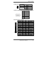
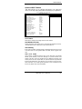
Connector Locations on 2807700A/2807700B
ATX1: 24-pin ATX Power Connector................................................................................................... 14
ATX2: ATX 12V Power Connector ...................................................................................................... 14
CPU_FAN1: CPU Fan Power Connector ............................................................................................. 14
PWR_FAN1: SYSTEM Fan Power Connectors ................................................................................... 14
CN2: PS/2 Keyboard and PS/2 Mouse Connectors ............................................................................... 15
CN1 J3: COM1/2 Serial Ports................................................................................................................ 15
VGA1: VGA CRT Connector ................................................................................................................ 16
CN3: Marvell 88E8053 PCI-express Gigabit LAN and USB6/7 Connector ........................................ 16
CN6: Intel 82562V 10/100 or Intel 82566DC GbE RJ-45 and USB4/5 Connector................................................. 16
CN4: Audio Connector .......................................................................................................................... 16
F_USB1: USB0/USB1 Connector ......................................................................................................... 17
S_ATA1, S_ATA2, S_ATA3, S_ATA4: SATA HDD Connectors ...................................................... 17
IDE1: Primary IDE Connectors ............................................................................................................. 17
J2: Digital I/O Connector (4 in, 4 out)................................................................................................... 18
J4: External Audio Connector for 7.1 channel ...................................................................................... 18
JP4: For LPC I/F Adaptor Card ............................................................................................................. 18
J5: Power LED ....................................................................................................................................... 18
J7: System Function Connector ............................................................................................................. 19
PCIE_1: x16 PCI Express Slot .............................................................................................................. 19
2807700 User’s Manual 13

INSTALLATIONS
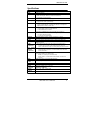
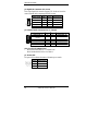
ATX1: 24-pin ATX Power Connector
Signal Name Pin # Pin # Signal Name
3.3V 13 1 3.3V
-12V 14 2 3.3V
Ground 15 3 Ground
PS-ON 16 4 +5V
Ground 17 5 Ground
Ground 18 6 +5V
Ground 19 7 Ground
-5V 20 8 Power good
+5V 21 9 5VSB
+5V 22 10 +12V
+5V 23 11 +12V
Ground 24 12 +3.3V
ATX2: ATX 12V Power Connector
This connector supplies the CPU operation voltage
Pin # Signal Name
1 Ground
2 Ground
3 +12V
4 +12V
CPU_FAN1: CPU Fan Power Connector
Pin # Signal Name
1 Control
2 Sense
3 +12V
4 Ground
PWR_FAN1: SYSTEM Fan Power Connectors
Pin # Signal Name
1 Sense
2 +12V
3 Rotation detection
14 2807700 User’s Manual

INSTALLATIONS
CN2: PS/2 Keyboard and PS/2 Mouse Connectors
Keyboard Signal Pin # Mouse Signal
Keyboard data 1 Mouse data
N.C. 2 N.C.
GND 3 GND
5V 4 5V
Mouse (top)
Keyboard (bottom)
Keyboard clock 5 Mouse clock
N.C. 6 N.C.
CN1 J3: COM1/2 Serial Ports
CN1 (COM1) is a DB-9 connector, while J3 are COM pin-header
connectors.
Signal Name Pin # Pin # Signal Name
DCD, Data carrier detect 1 6 DSR, Data set ready
RXD, Receive data 2 7 RTS, Request to send
TXD, Transmit data 3 8 CTS, Clear to send
DTR, Data terminal ready 4 9 RI, Ring indicator
GND, ground 5 10 Not Used
J3: COM2 is jumper selectable for RS-232, RS-422 and RS-485.
Pin # Signal Name
RS-232 R2-422 RS-485
1 DCD TX- DATA-
2 RX TX+ DATA+
3 TX RX+ NC
4 DTR RX- NC
5 Ground Ground Ground
6 DSR RTS- NC
7 RTS RTS+ NC
8 CTS CTS+ NC
9 RI CTS- NC
10 NC NC NC
2807700 User’s Manual 15

INSTALLATIONS
VGA1: VGA CRT Connector
VGA1 is a DB-15 VGA connector located beside the COM1 port. The
following table shows the pin-out assignments of this connector.
Signal Name Pin # Pin # Signal Name
Red 1 2 Green
Blue 3 4 N.C.
GND 5 6 GND
GND 7 8 GND
VCC 9 10 GND
N.C. 11 12 DDCDATA
HSYNC 13 14 VSYNC
DDCCLK 15
CN3: Marvell 88E8053 PCI-express Gigabit LAN and USB6/7
Connector
CN6: Intel 82562V 10/100 or Intel 82566DC GbE RJ-45 and
USB4/5 Connector
Note: 10/100 LAN for 2807700A; DUAL Gigabit LAN for 2807700F
CN4: Audio Connector
CN4 is a 3-jack audio connector
16 2807700 User’s Manual
Page is loading ...
Page is loading ...
Page is loading ...
Page is loading ...
Page is loading ...
Page is loading ...
Page is loading ...
Page is loading ...
Page is loading ...
Page is loading ...
Page is loading ...
Page is loading ...
Page is loading ...
Page is loading ...
Page is loading ...
Page is loading ...
Page is loading ...
Page is loading ...
Page is loading ...
Page is loading ...
Page is loading ...
Page is loading ...
Page is loading ...
Page is loading ...
Page is loading ...
Page is loading ...
Page is loading ...
Page is loading ...
Page is loading ...
Page is loading ...
Page is loading ...
Page is loading ...
Page is loading ...
Page is loading ...
Page is loading ...
Page is loading ...
Page is loading ...
Page is loading ...
Page is loading ...
Page is loading ...
Page is loading ...
Page is loading ...
Page is loading ...
Page is loading ...
Page is loading ...
Page is loading ...
-
 1
1
-
 2
2
-
 3
3
-
 4
4
-
 5
5
-
 6
6
-
 7
7
-
 8
8
-
 9
9
-
 10
10
-
 11
11
-
 12
12
-
 13
13
-
 14
14
-
 15
15
-
 16
16
-
 17
17
-
 18
18
-
 19
19
-
 20
20
-
 21
21
-
 22
22
-
 23
23
-
 24
24
-
 25
25
-
 26
26
-
 27
27
-
 28
28
-
 29
29
-
 30
30
-
 31
31
-
 32
32
-
 33
33
-
 34
34
-
 35
35
-
 36
36
-
 37
37
-
 38
38
-
 39
39
-
 40
40
-
 41
41
-
 42
42
-
 43
43
-
 44
44
-
 45
45
-
 46
46
-
 47
47
-
 48
48
-
 49
49
-
 50
50
-
 51
51
-
 52
52
-
 53
53
-
 54
54
-
 55
55
-
 56
56
-
 57
57
-
 58
58
-
 59
59
-
 60
60
-
 61
61
-
 62
62
-
 63
63
-
 64
64
-
 65
65
-
 66
66


GLOBAL AMICI Computer Hardware 2807700 User manual
- Category
- Motherboards
- Type
- User manual
Ask a question and I''ll find the answer in the document
Finding information in a document is now easier with AI
Other documents
-
Panasonic AGLA672E Operating instructions
-
Intel MB900-R User manual
-
 IBASE Technology SI-96 Series User manual
-
 IBASE Technology MB898F User manual
-
-
-
-
 Acrosser Technology AR-B1991 User manual
-
BCM BC945G User manual
-
American Megatrends MB980 User manual


