Page is loading ...

HSIM-A6DP
User’s Guide
HSIM-A6DP
RR
APIM 1 APIM 2


HSIM-A6DP User’s Guide i
NOTICE
Cabletron Systems reserves the right to make changes in specifications and other information
contained in this document without prior notice. The reader should in all cases consult Cabletron
Systems to determine whether any such changes have been made.
The hardware, firmware, or software described in this manual is subject to change without notice.
IN NO EVENT SHALL CABLETRON SYSTEMS BE LIABLE FOR ANY INCIDENTAL,
INDIRECT, SPECIAL, OR CONSEQUENTIAL DAMAGES WHATSOEVER (INCLUDING BUT
NOT LIMITED TO LOST PROFITS) ARISING OUT OF OR RELATED TO THIS MANUAL OR
THE INFORMATION CONTAINED IN IT, EVEN IF CABLETRON SYSTEMS HAS BEEN
ADVISED OF, KNOWN, OR SHOULD HAVE KNOWN, THE POSSIBILITY OF SUCH
DAMAGES.
Copyright 1997 by Cabletron Systems, Inc., P.O. Box 5005, Rochester, NH 03866-5005
All Rights Reserved
Printed in the United States of America
Order Number: 9032077-03 November 1997
Cabletron Systems
,
LANVIEW
,
and S
ECURE
F
AST
are registered trademarks;
HSIM
and
APIM
are trademarks of Cabletron Systems, Inc.
All other product names mentioned in this manual may be trademarks or registered trademarks of
their respective companies.
FCC NOTICE
This device complies with Part 15 of the FCC rules. Operation is subject to the following two
conditions: (1) this device may not cause harmful interference, and (2) this device must accept any
interference received, including interference that may cause undesired operation.
NOTE:
This equipment has been tested and found to comply with the limits for a Class A digital
device, pursuant to Part 15 of the FCC rules. These limits are designed to provide reasonable
protection against harmful interference when the equipment is operated in a commercial environment.
This equipment uses, generates, and can radiate radio frequency energy and if not installed in
accordance with the operator’s manual, may cause harmful interference to radio communications.
Operation of this equipment in a residential area is likely to cause interference in which case the user
will be required to correct the interference at his own expense.
WARNING:
Changes or modifications made to this device which are not expressly approved by the
party responsible for compliance could void the user’s authority to operate the equipment.
Only qualified personnel should perform installation
procedures.
Printed on Recycled Paper

Notice
ii HSIM-A6DP User’s Guide
DOC NOTICE
This digital apparatus does not exceed the Class A limits for radio noise emissions from digital
apparatus set out in the Radio Interference Regulations of the Canadian Department of
Communications.
Le présent appareil numérique n’émet pas de bruits radioélectriques dépassant les limites applicables
aux appareils numériques de la class A prescrites dans le Règlement sur le brouillage radioélectrique
édicté par le ministère des Communications du Canada.
VCCI NOTICE
This is a Class A product based on the standard of the Voluntary Control Council for Interference by
Information Technology Equipment (VCCI). If this equipment is used in a domestic environment,
radio disturbance may arise. When such trouble occurs, the user may be required to take corrective
actions.
CABLETRON SYSTEMS, INC. PROGRAM LICENSE AGREEMENT
IMPORTANT:
Before utilizing this product, carefully read this License Agreement.
This document is an agreement between you, the end user, and Cabletron Systems, Inc. (“Cabletron”)
that sets forth your rights and obligations with respect to the Cabletron software program (the
“Program”) contained in this package. The Program may be contained in firmware, chips or other
media. BY UTILIZING THE ENCLOSED PRODUCT, YOU ARE AGREEING TO BECOME
BOUND BY THE TERMS OF THIS AGREEMENT, WHICH INCLUDES THE LICENSE AND
THE LIMITATION OF WARRANTY AND DISCLAIMER OF LIABILITY. IF YOU DO NOT
AGREE TO THE TERMS OF THIS AGREEMENT, PROMPTLY RETURN THE UNUSED
PRODUCT TO THE PLACE OF PURCHASE FOR A FULL REFUND.

Notice
HSIM-A6DP User’s Guide iii
CABLETRON SOFTWARE PROGRAM LICENSE
1. LICENSE
. You have the right to use only the one (1) copy of the Program provided in this
package subject to the terms and conditions of this License Agreement.
You may not copy, reproduce or transmit any part of the Program except as permitted by the
Copyright Act of the United States or as authorized in writing by Cabletron.
2. OTHER RESTRICTIONS. You may not reverse engineer, decompile, or disassemble the
Program.
3. APPLICABLE LAW. This License Agreement shall be interpreted and governed under the laws
and in the state and federal courts of New Hampshire. You accept the personal jurisdiction and
venue of the New Hampshire courts.
EXCLUSION OF WARRANTY AND DISCLAIMER OF LIABILITY
1. EXCLUSION OF
WARRANTY. Except as may be specifically provided by Cabletron in
writing, Cabletron makes no warranty, expressed or implied, concerning the Program (including
its documentation and media).
CABLETRON DISCLAIMS ALL WARRANTIES, OTHER THAN THOSE SUPPLIED TO
YOU BY CABLETRON IN WRITING, EITHER EXPRESSED OR IMPLIED, INCLUDING
BUT NOT LIMITED TO IMPLIED WARRANTIES OF MERCHANTABILITY AND
FITNESS FOR A PARTICULAR PURPOSE, WITH RESPECT TO THE PROGRAM, THE
ACCOMPANYING WRITTEN MATERIALS, AND ANY ACCOMPANYING HARDWARE.
2. NO LIABILITY FOR CONSEQUENTIAL DAMAGES. IN NO EVENT SHALL
CABLETRON OR ITS SUPPLIERS BE LIABLE FOR ANY DAMAGES WHATSOEVER
(INCLUDING, WITHOUT LIMITATION, DAMAGES FOR LOSS OF BUSINESS,
PROFITS, BUSINESS INTERRUPTION, LOSS OF BUSINESS INFORMATION, SPECIAL,
INCIDENTAL, CONSEQUENTIAL, OR RELIANCE DAMAGES, OR OTHER LOSS)
ARISING OUT OF THE USE OR INABILITY TO USE THIS CABLETRON PRODUCT,
EVEN IF CABLETRON HAS BEEN ADVISED OF THE POSSIBILITY OF SUCH
DAMAGES. BECAUSE SOME STATES DO NOT ALLOW THE EXCLUSION OR
LIMITATION OF LIABILITY FOR CONSEQUENTIAL OR INCIDENTAL DAMAGES, OR
ON THE DURATION OR LIMITATION OF IMPLIED WARRANTIES, IN SOME
INSTANCES THE ABOVE LIMITATIONS AND EXCLUSIONS MAY NOT APPLY TO
YOU.
UNITED STATES GOVERNMENT RESTRICTED RIGHTS
The enclosed product (a) was developed solely at private expense; (b) contains “restricted computer
software” submitted with restricted rights in accordance with Section 52227-19 (a) through (d) of the
Commercial Computer Software - Restricted Rights Clause and its successors, and (c) in all respects
is proprietary data belonging to Cabletron and/or its suppliers.
For Department of Defense units, the product is licensed with “Restricted Rights” as defined in the
DoD Supplement to the Federal Acquisition Regulations, Section 52.227-7013 (c) (1) (ii) and its
successors, and use, duplication, disclosure by the Government is subject to restrictions as set forth in
subparagraph (c) (1) (ii) of the Rights in Technical Data and Computer Software clause at
252.227-7013. Cabletron Systems, Inc., 35 Industrial Way, Rochester, New Hampshire 03867-0505.

Notice
iv HSIM-A6DP User’s Guide
SAFETY INFORMATION
CLASS 1 LASER TRANSCEIVERS
THE FE-100F3 FAST ETHERNET INTERFACE MODULE, FPIM-05 AND
FPIM-07 FDDI PORT INTERFACE MODULES, AND APIM-29 ATM
PORT INTERFACE MODULE USE CLASS 1 LASER TRANSCEIVERS.
READ THE FOLLOWING SAFETY INFORMATION BEFORE
INSTALLING OR OPERATING THESE MODULES.
The Class 1 laser transceivers use an optical feedback loop to maintain Class 1 operation limits. This
control loop eliminates the need for maintenance checks or adjustments. The output is factory set, and
does not allow any user adjustment. Class 1 laser transceivers comply with the following safety
standards:
• 21 CFR 1040.10 and 1040.11 U.S. Department of Health and Human Services (FDA).
• IEC Publication 825 (International Electrotechnical Commission).
• CENELEC EN 60825 (European Committee for Electrotechnical Standardization).
When operating within their performance limitations, laser transceiver output meets the Class 1
accessible emission limit of all three standards. Class 1 levels of laser radiation are not considered
hazardous.
SAFETY INFORMATION
CLASS 1 LASER TRANSCEIVERS
LASER RADIATION AND CONNECTORS
When the connector is in place, all laser radiation remains within the fiber. The maximum amount of
radiant power exiting the fiber (under normal conditions) is -12.6 dBm or 55 x 10
-6
watts.
Removing the optical connector from the transceiver allows laser radiation to emit directly from the
optical port. The maximum radiance from the optical port (under worst case conditions) is
0.8 W cm
-2
or 8 x 10
3
W m
2
sr-1.
Do not use optical instruments to view the laser output. The use of optical instruments to view
laser output increases eye hazard. When viewing the output optical port, power must be
removed from the network adapter.

Notice
HSIM-A6DP User’s Guide v
DECLARATION OF CONFORMITY
Application of Council Directive(s):
89/336/EEC
73/23/EEC
Manufacturer’s Name:
Cabletron Systems, Inc.
Manufacturer’s Address:
35 Industrial Way
PO Box 5005
Rochester, NH 03867
European Representative Name:
Mr. J. Solari
European Representative Address:
Cabletron Systems Limited
Nexus House, Newbury Business Park
London Road, Newbury
Berkshire RG13 2PZ, England
Conformance to Directive(s)/Product Standards:
EC Directive 89/336/EEC
EC Directive 73/23/EEC
EN 55022
EN 50082-1
EN 60950
Equipment Type/Environment:
Networking Equipment, for use in a
Commercial or Light
Industrial
Environment.
We the undersigned, hereby declare, under our sole responsibility, that the equipment packaged
with this notice conforms to the above directives.
Manufacturer Legal Representative in Europe
Mr. Ronald Fotino Mr. J. Solari
___________________________________ ___________________________________
Full Name Full Name
Principal Compliance Engineer Managing Director - E.M.E.A.
___________________________________ ___________________________________
Title Title
Rochester, NH, USA Newbury, Berkshire, England
___________________________________ ___________________________________
Location Location

Notice
vi HSIM-A6DP User’s Guide

HSIM-A6DP User’s Guide vii
CONTENTS
CHAPTER 1 INTRODUCTION
1.1 Using This Manual.......................................................................1-2
1.2 Document Conventions...............................................................1-2
1.3 Overview......................................................................................1-3
1.4 Features ......................................................................................1-3
1.5 Specifications ..............................................................................1-4
1.6 Related Manuals..........................................................................1-4
1.7 Getting Help.................................................................................1-5
CHAPTER 2 INSTALLATION
2.1 Unpacking the HSIM....................................................................2-1
2.2 Installing APIMs...........................................................................2-2
2.3 Installing an HSIM .......................................................................2-4
2.3.1 Installing an HSIM in an Interface Module......................2-4
2.3.2 Installing an HSIM in a Standalone Hub.........................2-7
CHAPTER 3 LOCAL MANAGEMENT
3.1 Local Management Keyboard Conventions.................................3-2
3.2 Navigating Local Management Screens......................................3-3
3.2.1 Selecting Local Management Menu Screen Items .........3-3
3.2.2 Exiting Local Management Screens ...............................3-3
3.3 Accessing Local Management.....................................................3-5
3.4 The HSIM-A6DP ATM Screen.....................................................3-6
3.5 The ATM Connections Screen ....................................................3-7
3.5.1 ATM Connections Screen Fields ....................................3-8
3.6 The ATM Connection Setup Screen............................................3-9
3.6.1 ATM Connection Setup Screen Fields..........................3-10
3.7 The Add/Delete Entry Screen....................................................3-12
3.7.1 Add/Delete Entry Screen Fields....................................3-12
3.7.2 Adding an Entry (PVC) .................................................3-13
3.7.3 Modifying an Entry (PVC) .............................................3-14
3.7.4 Deleting an Entry (PVC) ...............................................3-14

Contents
viii HSIM-A6DP User’s Guide
3.8 The ATM Redundancy Configuration Screen ............................3-15
3.8.1 ATM Redundancy Configuration Screen Fields............3-16
3.8.2 Setting the Redundancy Status.....................................3-18
3.8.3 Setting the Primary Port................................................3-18
3.8.4 Setting the Active Port...................................................3-18
3.8.5 Setting the Activation of Redundant Port Field..............3-19
3.8.6 Setting the Revert to Primary Port Field........................3-19
3.8.7 Setting the Periodic Test Status Field...........................3-20
3.8.8 Setting the Periodic Test Time......................................3-20
3.8.9 Using the TEST PORTS NOW Command....................3-21
3.8.10 Using the RESET TO FACTORY DEFAULTS
Command......................................................................3-21
3.9 The ATM LEC Screen................................................................3-22
3.9.1 ATM LEC Screen Fields................................................3-23
3.10 The ATM LEC Table Screen......................................................3-24
3.10.1 ATM LEC Table Screen Fields......................................3-25
3.11 The LEC Administration Screen.................................................3-27
3.11.1 LEC Administration Screen Fields.................................3-28
3.11.2 Changing the LEC Status (MODIFY MODE Only)........3-30
3.11.3 Configuring the LEC Automatically
(CREATE MODE Only).................................................3-30
3.11.4 Configuring the LEC Manually
(CREATE MODE Only).................................................3-31
3.11.5 Modifying an Existing LEC ............................................3-32
3.11.6 Deleting an Existing LEC...............................................3-33
3.12 The ELAN Properties Screen.....................................................3-34
3.12.1 ELAN Properties Screen Fields.....................................3-34
3.13 The LEC ARP Cache Screen.....................................................3-37
3.13.1 LEC ARP CACHE Screen Fields ..................................3-38
3.14 The LEC ARP Cache Search Screen ........................................3-40
3.14.1 LEC ARP Cache Search Screen Fields........................3-41
3.14.2 Performing a Search .....................................................3-41
3.15 The Signalling Screen................................................................3-44
3.15.1 Signaling Screen Fields.................................................3-45
3.15.2 Changing the ILMI Status..............................................3-46
3.15.3 Disabling the ILMI Status ..............................................3-47
3.15.4 Changing the UNI Status...............................................3-48
3.15.5 Restarting UNI...............................................................3-48
3.15.6 Restarting the ILMI........................................................3-48
3.15.7 Setting the UNI Version.................................................3-49
3.16 The Discovery ELAN Setup Screen...........................................3-50
3.16.1 ATM Discovery ELAN Setup Screen Fields..................3-51
3.16.2 Assigning the HSIM-A6DP to a discovery ELAN...........3-52
3.17 Using the Bandwidth Allocation Mode Feature..........................3-54

Contents
HSIM-A6DP User’s Guide ix
3.18 Enabling the Bandwidth Allocation Mode Feature.....................3-54
3.19 Creating PVCs with the Bandwidth Allocation Mode Enabled...3-57
3.19.1 ATM Connection Setup Screen Fields..........................3-58
3.20 The Add/Delete Entry Screen....................................................3-60
3.20.1 Add/Delete Entry Screen Fields....................................3-60
3.20.2 Adding an Entry (PVC) .................................................3-62
3.20.3 Modifying an Entry (PVC) .............................................3-63
3.20.4 Deleting an Entry (PVC) ...............................................3-64
CHAPTER 4 LANVIEW LEDs
4.1 HSIM-A6DP LEDs.......................................................................4-1
APPENDIX A APIM SPECIFICATIONS
A.1 APIM-11 Specifications ...............................................................A-1
A.2 APIM-21 Specifications ...............................................................A-2
A.3 APIM-29 Specifications ...............................................................A-3
A.4 APIM-29LR Specifications...........................................................A-4
A.5 APIM-22 Specifications ...............................................................A-5
A.6 APIM-67 Specifications ...............................................................A-6

Contents
x HSIM-A6DP User’s Guide

HSIM-A6DP User’s Guide 1-1
CHAPTER 1
INTRODUCTION
Welcome to the Cabletron Systems
HSIM-A6DP User’s Guide
. This
manual provides the following information:
•
Describes HSIM-A6DP features
•
Explains how to install the HSIM-A6DP in a Cabletron Systems
interface module or standalone hub
•
Outlines specifications for the Cabletron Systems Asynchronous
Transfer Mode (ATM) High Speed Interface Module (HSIM)
The HSIM-A6DP provides additional connectivity/functionality to
various Cabletron Systems interface modules and standalone hubs. You
should have a general working knowledge of ATM networks prior to
installing the HSIM-A6DP.
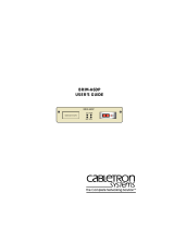
Figure 1-1 The HSIM-A6DP
HSIM-A6DP
RR
APIM 1 APIM 2
20770

Chapter 1:
Introduction
1-2 HSIM-A6DP User’s Guide
1.1 USING THIS MANUAL
Read through this manual completely to familiarize yourself with its
content and to gain an understanding of the features and capabilities of
the HSIM-A6DP. The following list provides an overview of each section
of this manual:
Chapter 1,
Introduction
, outlines the contents of this manual, describes
HSIM-A6DP features and concludes with a list of related manuals.
Chapter 2,
Installation
, describes how to install ATM Port Interface
Modules (APIMs) into the HSIM-A6DP. This chapter also explains how
to install an HSIM-A6DP into an interface module or a standalone hub.
Chapter 3,
Local Management
, describes how to use the HSIM-A6DP
Local Management screens to configure the HSIM-A6DP for connection
to an ATM network.
Chapter 4,
LANVIEW LEDs
, describes how to use the HSIM-A6DP
LEDs to monitor HSIM performance and status.
Appendix A,
APIM Specifications
, describes specifications and features
for each of the APIMs available for the HSIM-A6DP.
1.2 DOCUMENT CONVENTIONS
The following conventions are used throughout this document:
NOTE
Note
symbol. Calls the reader’s attention to any item of
information that may be of special importance.
!
CAUTION
Caution
symbol. Contains information essential to avoid
damage to the equipment.
Electrical Hazard Warning
symbol. Warns against an action
that could result in personal injury or death due to an electrical
hazard.

Overview
HSIM-A6DP User’s Guide 1-3
1.3 OVERVIEW
The HSIM-A6DP extends the functionality of your Cabletron Systems
interface module or standalone hub to include remote uplink capability. It
allows remote connectivity using ATM technology.
Two APIMs can be installed in the HSIM-A6DP, to provide redundant
ATM links from the HSIM to a switched ATM network. Cabletron
Systems provides a variety of APIMs that let you select the configuration
of your choice. If port redundancy is not a requirement, then only one
APIM needs to be installed.
The HSIM-A6DP supports two types of Virtual Channels: Permanent
Virtual Channels (PVCs), and Switched Virtual Channels (SVCs), which
are compliant with the ATM Forum’s User-Network-Interface (UNI) for
SVC signaling specification.
1.4 FEATURES
ATM Port Interface Modules (APIMs)
The HSIM-A6DP supports two Cabletron Systems APIMs for ATM
connectivity and redundancy. You can easily install APIMs into the
HSIM-A6DP for the interface of your choice. The two APIMs installed
may be of any combination of physical layer cable type and bandwidth.
For example the APIM installed in slot 1 could support Twisted Pair cable
and provide 155 Mbps of bandwidth, while the APIM installed in slot 2
could support Coaxial cable and provide 45 Mbps of bandwidth.
Appendix A,
APIM Specifications
, details all of the APIMs available for
the HSIM-A6DP.
MIB Support
For additional information on how to extract and compile individual
MIBs, refer to the Release Notes, or contact Cabletron Systems Technical
Support (refer to Section 1.7,
Getting Help
).
LANVIEW Diagnostic LEDs
Cabletron Systems provides a visual diagnostic and monitoring system
called LANVIEW. The HSIM-A6DP LANVIEW LEDs help you to
quickly identify transmit/receive and link status.

Chapter 1:
Introduction
1-4 HSIM-A6DP User’s Guide
1.5 SPECIFICATIONS
This section describes environment specifications and safety requirements
for the HSIM-A6DP. Cabletron Systems reserves the right to change these
specifications at any time without notice.
Environment
Operating Temperature: 5
°
C to 40
°
C (41
°
F to 104
°
F)
Storage Temperature: -30
°
C to 73
°
C (-22
°
F to 164
°
F)
Operating Relative Humidity: 5% to 90% (non-condensing)
Regulatory Compliance
Safety: UL 1950, CSA C22.2 No. 950,
EN 60950, IEC 950, and 73/23/EEC
Electromagnetic
Compatibility (EMC): FCC Part 15, VCCI V-3, EN 55022,
CSA C108.8, EN 50082-1, 89/336/EEC,
AS/NZS 3548
1.6 RELATED MANUALS
Use the following manuals to supplement the procedures and other
technical data provided in this manual.
Cabletron Systems
ATM Technology Guide
Cabletron Systems
Cabling Guide
The manuals referenced above can be obtained on the World Wide Web in
Adobe Acrobat Portable Document Format (PDF) at the following site:
http://www.cabletron.com/
NOTE
The documentation for the interface module or standalone hub
in which the HSIM-A6DP will be installed will also assist you in
the installation and setup of the HSIM-A6DP.

Getting Help
HSIM-A6DP User’s Guide 1-5
1.7 GETTING HELP
If you need additional support related to this device, or if you have any
questions, comments, or suggestions concerning this manual, contact the
Cabletron Systems Global Call Center:
Before calling the Cabletron Systems Global Call Center, have the
following information ready:
•
Your Cabletron Systems service contract number
•
A description of the failure
•
A description of any action(s) already taken to resolve the problem
(e.g., changing mode switches, rebooting the unit, etc.)
•
The serial and revision numbers of all involved Cabletron Systems
products in the network
•
A description of your network environment (layout, cable type, etc.)
•
Network load and frame size at the time of trouble (if known)
•
The device history (i.e., have you returned the device before, is this a
recurring problem, etc.)
•
Any previous Return Material Authorization (RMA) numbers
Phone (603) 332-9400
Internet mail suppor[email protected]
FTP ctron.com (134.141.197.25)
Login
anonymous
Password
your email address
BBS (603) 335-3358
Modem setting 8N1: 8 data bits, No parity, 1 stop bit
For additional information about Cabletron Systems or our products,
visit our World Wide Web site:
http://www.cabletron.com/
For technical support, select
Service and Support
.

Chapter 1:
Introduction
1-6 HSIM-A6DP User’s Guide

HSIM-A6DP User’s Guide 2-1
CHAPTER 2
INSTALLATION
This chapter contains instructions for the following tasks:
• Unpacking the HSIM (Section 2.1)
• Installing APIMs (Section 2.2)
• Installing an HSIM (Section 2.3)
To install the HSIM and APIMs, you need the following tools:
• Antistatic wrist strap (provided with the 6C105 chassis or standalone
hub)
• Phillips screwdriver
2.1 UNPACKING THE HSIM
Unpack the HSIM as follows:
1. Remove the shipping box material covering the HSIM.
2. Carefully remove the module from the shipping box. Leave the
module in its non-conductive bag until you are ready to install the
module.
3. Attach the antistatic wrist strap (refer to the instructions on the
antistatic wrist strap package).
4. After removing the module from its non-conductive bag, visually
inspect the device. If you notice any signs of damage, contact
Cabletron Systems Global Call Center immediately. Refer to
Section 1.7.
!
CAUTION
The HSIM-A6DP and the host module or hub are sensitive to
static discharges. Use an antistatic wrist strap and observe all
static precautions during this procedure. Failure to do so could
result in damage to the HSIM-A6DP, the host module, or hub.

Chapter 2: Installation
2-2 HSIM-A6DP User’s Guide
2.2 INSTALLING APIMs
To install an APIM into the HSIM-A6DP, refer to Figure 2-1 and
Figure 2-2 and perform the following steps:
1. Attach the antistatic wrist strap (refer to the instructions on the
antistatic wrist strap package).
2. Remove and save the three faceplate screws attaching the faceplate to
the HSIM. Remove the HSIM faceplate.
3. Remove and save the three screws from the HSIM standoffs. Remove
the APIM coverplate.
4. Insert the APIM connector into the HSIM connector pins.
Figure 2-1 Removing the APIM Coverplate
Only qualified personnel should install or service this unit.
207733
APIM
Coverplate
Standoff Screws
HSIM Standoffs
/