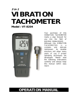
p
oc
k
et typ
e
PHOTO/CONTAC
T
TACHOMETER
Model : DT-2230
Y
our purchase of this
PHOTO/CONTACT
T
ACHOMETER marks a
step forward for you into
the field of precision
measurement. Although
this TACHOMETER is a
complex and delicate
instrument, its durable
structure will allow many
years of use if proper
operating techniques are
developed. Please read
the following instructions
carefully and always keep
this manual within easy
reach.
OPERATION MANUAL

TABLE OF CONTENTS
1 FEATURES................................................................ 1
2 SPECIFICATIONS......................................................
.
2
3 FRONT PANEL DESCRIPTION..................................... 4
3-1 Display..............................................................
.
4
3-2 Power Button..................................................... 4
3-3 Function Button.................................................
.
4
3-4 Memory Button..................................................
.
4
3-5 Surface Speed Wheel.........................................
.
4
3-6 RPM Adapter ( Contact Tach. )............................ 4
3-7 Photo Tach. detect sensor..................................
.
4
3-8 Laser Light Beam...............................................
.
4
3-9 Battery Cover/Compartment...............................
.
4
3-10 Reflecting Mark.................................................
.
4
3-11 Monitor indicator............................................... 4
3-12 RS-232 Output Terminal....................................
.
4
4 MEASURING PROCEDURES....................................... 5
4-1 Change the function............................................ 5
4-2 Photo RPM measurement..................................... 6
4-3 Contact RPM measurement.................................. 6
4-4 Surface Speed Measurement................................ 7
5 OPERATION PROCEDURE FOR MEMORY RECALL........ 7
6 BATTERY REPLACEMENT........................................... 8
7. RS232 PC SERIAL INTERFACE...................................
.
8
8 PATENT....................................................................10

1. FEATURES
* Compact and pocket tachometer.
* The best Tachometer in the world. 2 in 1, one
instrument combine Photo tachometer and Contact
Tachometer.
* Photo tachometer uses Laser light detecting source,
long measuring range up to 1.5 meters, it is useful in
the RPM measurement application where the machine
would be a risk to the operator or close access is
difficult or not possible.
* Wide measuring range from 0.5 to 100,000 RPM, 0.1
RPM resolution for the measured value < 1000 RPM.
* Microprocessor based circuit, crystal time base, high
precision with 0.1% accuracy.
* High visible LCD display gives RPM reading exactly
with no guessing or errors & saves battery energy.
* Memory with recall function, the last value, max., value,
min. value will be stored into the memory automatically.
* The use of durable, long lasting components, including
a strong, light weight ABS plastic housing, assures
almost maintenance free performance for many years.
* RS232 PC serial interface.
* The tachometer have patent patented, refer page 10.
1

2. SPECIFICATIONS
Measurement
Photo Tachometer :
& Range 5 to 99,999 RPM.
Contact Tachometer :
0.5 to 19,999 RPM.
Surface Speed :
m/min. - 0.05 to 1,999.9 m/min.
ft/min. - 0.2 to 6,560 ft/min.
in/min. - 2.0 to 78,740 in/min.
Resolution
RPM
0.1 RPM ( < 1,000 RPM ).
1 RPM ( 1,000 RPM ).≧
m/min.
0.01 m/min. ( < 100 m/min. ).
0.1 m/min. ( 100 m/min. ).≧
ft/min.
0.1 ft/min. ( < 1,000 ft/min. ).
1 ft/min. ( 1,000 ft/min. ).≧
in/min.
0.1 in/min. ( < 1,000 in/min. ).
1 in/min. ( 1,000 in/min. ).≧
Display LCD, size 32 mm x 28 mm.
5 digits with display unit.
Accuracy ± ( 0.1% + 1 digit ).
@ reading
Photo 5 to 150 cm typically.
Tachometer * Spec. of detecting distance are that
detecting under the size of reflecting tape is
distance 10 mm square & the measuring RPM
value is 1,800 RPM. The max. & min.
detecting distance may change
under different environment,
different reflecting tape or the
measuring RPM beyond 1800 RPM.
2

Time base Quartz crystal.
Circuit Exclusive one-chip of microcomputer
LSI circuit.
Photo Tach. * Less than 1 mW.
Laser light * Class 2 laser diode.
source Red Wave length is 645 nm
approximately.
Operating 0 to 50 ( 32 to 122 ).℃℉
Temperature
Operating Less than 80% R.H.
Humidity
Memory Memorize Last/Max./Min. value
with recall.
Data Output RS232 PC serial interface.
Battery 4 x 1.5V AAA ( UM4 ) batteries.
Power
Photo tachometer :
Consumption Approx. DC 20 mA.
Contact tachometer :
Approx. DC 9.5 mA.
Size 165 x 50 x 33 mm.
( 6.5 x 2.0 x 1.3 inch ).
Weight 182 g ( 0.4 LB ).
* Weight is cluded the batteries.
Accessories Reflecting tape marks
Included ( 600 mm )................................
.
1 PC.
Operation manual.......................1 PC.
Spare RPM cone rubber..............
.
1 PC.
Spare RPM funnel rubber............
.
1 PC.
Optional * Carrying case, CA-52A
Accessory * RS232 cable, UPCB-02.
* Data Acquisition software,
SW-U801-WIN.
3

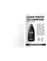
3. FRONT PANEL DESCRIPTION
Fig. 1
3-1 Display
3-2 Power Button
3-3 Function Button
3-4 Memory Button
3-5 Surface Speed Wheel
3-6 RPM Adapter ( Contact Tach. )
3-7 Photo Tach. detect sensor
3-8 Laser Light Beam
3-9 Battery Cover/Compartment
3-10 Reflecting Mark
3-11 Monitor indicator
3-12 RS-232 Output Terminal
4

4. MEASURING PROCEDURE
4-1 Change the function
1)Press the " Power Button " ( 3-2, Fig. 1 ) continuously
and not release the finger from the button.
2)Press " Function Button " ( 3-3, Fig. 1 ) momentarily in
sequence, the function will change to
a.Contact RPM measurement, display shows
" RPM " symbol.
b.Surface speed ( m/min. ) measurement,
display shows " m/min " symbol.
c. Surface speed ( ft/min. ) measurement,
display shows " ft/min " symbol.
d.Surface speed ( in/min. ) measurement,
display shows " in/min " symbol.
e.Photo RPM measurement, display shows "
RPM " symbol, at the same the " Laser
Light Beam " ( 3-8, Fig. 1 ) will be generated.
Note :
* After the function be selected, release the
buttons, the function will saved into the meter
even turn off the meter.
* Turn on the meter again, the existing select
function will present .
5

4-2 Photo RPM measurement
1)Select ( default ) the function to " Photo RPM ", refer
chapter 4-1, page 5.
2)Apply a " Reflecting Mark " ( 3-10, Fig. 1 ) to the
object being measured. Press the " Power Button "
( 3-2, Fig. 1 ) continuously and align the " Laser Light
Beam " ( 3-8, Fig. 1 ) with the applied target. Verify
that the " Monitor Indicator " ( 3-11, Fig. 1 ) lights
when the target pass through the light beam.
Measuring consideration :
If the measured RPM values is very low ( for
example less than 50 RPM ), recommend to attach
more " Reflecting Marks " average to the object. It
will get the real RPM with high resolution, precisely
& fast sampling time when divided the reading
values by the no. of the " Marks ".
4-3 Contact RPM measurement
1)Select ( default ) the function to " Contact RPM ", refer
chapter 4-1, page 5.
2)Press the " Power Button " ( 3-2, Fig. 1 ) & lightly
pressing the " RPM Adapter " ( 3-6, Fig. 1 ) against the
center hole on the hole of the measured rotating axis.
Release the " Measuring Button " when the reading
stabilizes ( approx. 2 sec. ).
6

4-4 Surface Speed Measurement
1)Select ( default ) the function to surface speed " m/min "
" ft/min " or " in/min " refer chapter 4-1, page 5.
2)Press the " Power Button " ( 3-2, Fig. 1 ) and simply
attaching the " Surface Speed Wheel " ( 3-5, Fig. 1 ) to
the detector. Release the " Power Button " when the
reading stabilizes ( approx. 2 sec. ).
5. OPERATION PROCEDURE FOR
MEMORY RECALL
1)The readout of " last value ", " max. value " & " min.
value " can be obtained immediately & memorized
into the circuit automatically after turning off the
"Measuring Button".
2)When have finished the measuring procedures ( after
release the measuring button ), the memorized values
can be displayed on the LCD display whenever :
a.First push the " Memory Button " ( 3-4, Fig. 1 ) -
To display the last value ( " LA " and " the last value "
will be displayed alternately ).
b.Second, push the " Memory Button " again -
To display the maximum value ( " UP " and " the
max. value " will be displayed alternately).
c. Third, push the " Memory Button " again -
To display the minimum value ( " dn " and " the min.
value " will be displayed alternately ).
7

6. BATTERY REPLACEMENT
*Replace the batteries when the LCD displays the low
battery icon " LO ", using 4 fresh 1.5 V ( UM4,
AAA ) batteries.
*To change the batteries, open the " Battery Cover "
( 3-9, Fig. 1 ).
*Make sure the " Battery cover " ( 3-9, Fig 1 ) is secured
after changing the batteries.
7. RS232 PC SERIAL INTERFACE
The instrument has RS232 PC serial interface via a 3.5
mm terminal ( 3-12, Fig. 1 ).
The data output is a 16 digit stream which can be
utilized for user's specific application.
A RS232 lead with the following connection will be
required to link the instrument with the PC serial port.
8

Meter PC
(3.5 mm jack plug) (9W 'D" Connector)
Center Pin..........................Pin 4
Ground/shield.....................Pin 2
2.2 K
resister
Pin 5
The 16 digits data stream will be displayed in the
following format :
D15 D14 D13 D12 D11 D10 D9 D8 D7 D6 D5 D4 D3 D2 D1 D0
Each digit indicates the following status :
D15 Start Word = 02
D14 4
D13 1
D12 & Annunciator for Display
D11 RPM = 27 ft/min = 11 m/min = 60
in/min = 28
D10 Polarity
0 = Positive 1 = Negative
D9 Decimal Point(DP), position from right to the
left
0 = No DP, 1= 1 DP, 2 = 2 DP, 3 = 3 DP
D8 to D1 Display reading, D8 = MSD, D1 = LSD
For example :
If the display reading is 1234, then D8 to
D1 is : 00001234
D0 End Word = 0D
9

RS232 setting
Baud rate 9600
Parity No parity
Data bit no. 8 Data bits
Stop bit 1 Stop bit
8. PATENT
This photo/contact combination tachometer had
the patent in the following countries :
USA - 4,823,080,
GERMANY - G9015492.4 G8708922.0
TAIWAN - 45478,
10
0511-DT2230
/