Page is loading ...

701 S. RIDGE AVENUE
TROY, OHIO 45374-0001
937 332-3000
www.hobartcorp.com
FORM 34622 Rev. B (Sep. 2003)
HO210 SERIES RACK OVENS
WITH ELECTRONIC OVEN CONTROL
MODEL
HO210E1 (ELECTRIC) ML-132180
HO210E2 (ELECTRIC) ML-132181
HO210G1 (GAS) ML-132182
HO210G2 (GAS) ML-132183

IMPORTANT FOR YOUR SAFETY
THIS MANUAL HAS BEEN PREPARED FOR PERSONNEL QUALIFIED TO INSTALL GAS
EQUIPMENT, WHO SHOULD PERFORM THE INITIAL FIELD START-UP AND
ADJUSTMENTS OF THE EQUIPMENT COVERED BY THIS MANUAL.
POST IN A PROMINENT LOCATION THE INSTRUCTIONS TO BE FOLLOWED IN THE
EVENT THE SMELL OF GAS IS DETECTED. THIS INFORMATION CAN BE OBTAINED
FROM THE LOCAL GAS SUPPLIER.
IMPORTANT
IN THE EVENT A GAS ODOR IS DETECTED, SHUT DOWN
UNITS AT MAIN SHUTOFF VALVE AND CONTACT THE LOCAL
GAS COMPANY OR GAS SUPPLIER FOR SERVICE.
FOR YOUR SAFETY
DO NOT STORE OR USE GASOLINE OR OTHER FLAMMABLE
VAPORS OR LIQUIDS IN THE VICINITY OF THIS OR ANY
OTHER APPLIANCE.
WARNING: IMPROPER INSTALLATION, ADJUSTMENT,
ALTERATION, SERVICE OR MAINTENANCE CAN CAUSE
PROPERTY DAMAGE, INJURY OR DEATH. READ THE
INSTALLATION, OPERATING AND MAINTENANCE
INSTRUCTIONS THOROUGHLY BEFORE INSTALLING OR
SERVICING THIS EQUIPMENT.
IN THE EVENT OF A POWER FAILURE, DO NOT ATTEMPT TO
OPERATE THIS DEVICE.
KEEP AREA AROUND OVEN CLEAR OF COMBUSTIBLES. DO
NOT OBSTRUCT COMBUSTION AND VENTILATION OPENINGS
ON THE OVEN.
– 2 –
© HOBART CORPORATION, 2001

– 3 –
MODEL HO210G1

– 4 –
TABLE OF CONTENTS
GENERAL .............................................................................................................................................5
INSTALLATION ....................................................................................................................................5
OPERATION.........................................................................................................................................6
Controls ...........................................................................................................................................6
Control Guide ..................................................................................................................................7
Oven Preheat ..................................................................................................................................8
Basic Operation ..............................................................................................................................9
Programming the Quick Set Menu .............................................................................................. 10
Temperature and Timer Control Settings ................................................................................... 12
Shutdown ...................................................................................................................................... 13
Cleaning ........................................................................................................................................ 13
MAINTENANCE................................................................................................................................. 14
General ......................................................................................................................................... 14
Preventive Maintenance .............................................................................................................. 14
Service and Parts Information..................................................................................................... 14
TROUBLESHOOTING ...................................................................................................................... 14
OWNER PREVENTIVE MAINTENANCE PROCEDURE .............................................................. 15
Introduction ................................................................................................................................... 15
Preventive Maintenance Procedure ........................................................................................... 15

– 5 –
OPERATION AND CARE OF
MODELS HO210G1/HO210G2 GAS RACK OVENS
and HO210E1/HO210E2 ELECTRIC RACK OVENS
KEEP THIS MANUAL FOR FUTURE USE
GENERAL
Models HO210G1/HO210G2 (gas) and HO210E1/HO210E2 (electric) Rack Ovens accommodate
roll-in racks. They are equipped with an electronic oven control for baking and/or steaming applications.
A mechanism in the ceiling rotates the rack during baking.
Model HO210G1 is rated at 175,000 Btu/hr (natural gas). Model HO210G2 is rated at 290,000 Btu/hr
(natural gas) and 250,000 Btu/hr (propane gas). Model HO210E1 is rated at 39 kW (electric) and model
HO210E2 is rated at 52 kW (electric).
Hobart Rack Ovens are produced with quality workmanship and material. Proper installation, usage
and maintenance of your rack oven will result in many years of satisfactory performance.
It is suggested that you thoroughly read this manual and carefully follow the instructions provided.
INSTALLATION
HO210 series ovens must be installed, started and tested or moved only by authorized Hobart Bakery
Systems trained service technicians.

– 6 –
OPERATION
WARNING: THE RACK OVEN AND ITS PARTS ARE HOT. USE CARE WHEN OPERATING,
SERVICING OR CLEANING THE OVEN.
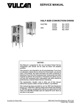
CONTROLS
PL-53621
SET
TEMP.
OVEN
TEMP.
Actual Temperature In Oven
Max.Temp. 525 F / 274 C
HEAT ON
OO
TIMER
STEAM
DELAY
(AIRFLOW)
ON
Seconds
ON
Minutes
Minutes Set
Remaining
Heat is disabled
during this delay
ON
QUICK
SET
Number 0-84
TEMP.
CLEAR
or SET
TIMER
CLEAR
or SET
STEAM
CLEAR
or SET
DELAY
CLEAR
or SET
QUICK
SET
START
STOP
RESUME
CLEAR
or SET
1
23
4
5
8
6
7
90
OPEN (LIT)
VENT POWER PULSE
AIRFLOW
CLOSED (OFF) OFF OFF
ON AUTO
Control Hints
• The vent feature helps control humidity.
• The steam option requires 20 to 30 minutes
to recover prior to each use.
• For delicate baked goods, use the PULSE
AIRFLOW option.
• When first initiated, the vent stays open for
90 seconds, closes for 115 seconds and
reopens for 5 seconds. After the first venting
is complete, the vent will open for 5 seconds
every 115 seconds throughout the baking
cycle.

– 7 –
CONTROL GUIDE
YEK NOITCA YALPSID
.PMET .erutarepmetderisedehttesotsserP
.dapyekrebmunehtgnisueulavehtretnE
tesehtsyalpsidwodniw.PMETTES
eblliwthgilNOTAEHehT.erutarepmet
.gnitaeherpsinevoehtelihwdetanimulli
tesehtdehcaersahnevoehtnehW
oglliwthgilNOTAEHeht,erutarepmet
ehtsyalpsidwodniw.PMETNEVOehT.ffo
.erutarepmetnevolautca
REMIT ehttesotsserPREMITemitehtretnE.
.dapyekrebmunehtgnisu
tessetunimsyalpsidwodniwREMITehT
tnerrucehtrofgniniamersetunimdna
nehwknilblliwthgilNOehT.elcycgnikab
ehtREMIT.evitcasi
SMAET ehttesotsserPMAETSehtretnE.noitpo
ehtnognimaetsrofemitfotnuoma
ehT.TRATSsserpneht,dapyekrebmun
.TRATSgnisserpretfaknilblliwthgilNO
tnuomaehtsyalpsidwodniwMAETSehT
maetsehtroftes)sdnocesni(emitfo
maetsnehwknilblliwthgilNOehT.elcyc
.evitcasimetsys
YALED ehttesotsserPYALEDehtretnE.noitpo
rebmunehtnosetunimforebmunderised
thgilNOehT.TRATSsserpneht,dapyek
.TRATSgnisserpretfaknilblliw
tnuomaehtsyalpsidwodniwYALEDehT
ehttaht)setunimni(emitfoYALEDnoitpo
yaleD.elcycgnikabehtgnirudetarepolliw
ehtfogninnigebehttawolfriaseziminim
ehtelihwdelbasidsitaeH.elcycgnikab
YALEDthgilNOehT.detavitcasinoitpo
si)WOLFRIA(YALEDnehwknilblliw
.evitca
TESKCIUQ ehtretnE.sgnittesderotsllacerotsserP
.dapyekrebmunehtnorebmunteSkciuQ
ehTTESKCIUQehtsyalpsidwodniw
.margorpteSkciuQtnerruc
TNEV stnevyldiparsihT.tnevehtnepootsserP
gnitnevehtsnigebdnarebmahcekabeht
ynatadetavitcaebnactnevehT.elcyc
.elcycgnikabehtgnirudemit
TNEVsielcyctnevehtnehwtilsithgil
.delbane
REWOP nevoehtnrutothctiwselggotehtpilF
.FFOroNOrewopniam
.nosinevoehtnehwtilerasyalpsidniaM
WOLFRIAESLUP nurotnafnevoehtwollaotsserP
rofffo,setunim2rofno(yltnettimretni
,elcycgnikabehttuohguorht)etunim1
.ekabeltneganignitluser
WOLFRIAESLUPehtnehwtilsithgil
.delbanesielcycwolfriaeslup

– 8 –
PL-53621
SET
TEMP.
OVEN
TEMP.
Actual Temperature In Oven
Max.Temp. 525 F / 274 C
HEAT ON
OO
TIMER
STEAM
DELAY
(AIRFLOW)
ON
Seconds
ON
Minutes
Minutes Set
Remaining
Heat is disabled
during this delay
ON
QUICK
SET
Number 0-84
TEMP.
CLEAR
or SET
TIMER
CLEAR
or SET
STEAM
CLEAR
or SET
DELAY
CLEAR
or SET
QUICK
SET
START
STOP
RESUME
CLEAR
or SET
1
23
4
5
8
6
7
90
OPEN (LIT)
VENT POWER PULSE
AIRFLOW
CLOSED (OFF) OFF OFF
ON AUTO
OVEN PREHEAT
For the best results, the oven must be preheated
before baking begins.
1. Turn the power switch to the ON position.
2. Press TEMP. and enter the desired baking
temperature on the number keypad.
3. Confirm that the doors are closed. This
enables the rack carrier to lift and rotate.
4. Allow 20 minutes after the oven has reached
the set temperature for the steam system to
charge. The actual oven temperature is
displayed in the OVEN TEMP. window.
5. The oven is now ready for baking operations.

– 9 –
BASIC OPERATION
WARNING: THE OVEN AND ITS PARTS ARE HOT. TO PREVENT BURNS, USE HOT PADS OR
PROTECTIVE MITTS WHEN LOADING OR UNLOADING THE OVEN.
1. Preheat the oven.
2. Confirm that the door is closed. This enables the rack carrier to lift and rotate.
3. Manually select baking settings:
• Press TIMER and enter the desired value on the number keypad. Repeat this step for
STEAM and DELAY.
4. Slowly open the door. Wait for the rack carrier to stop and lower.
Loading Procedure
1. The rack carrier is equipped with a stop on both ends. Manually flip the front carrier stop open (lead
flap up) to load the rack.
2. Roll the loaded rack onto the oven rack carrier until it touches the rack stop and then latch the front
carrier stop.
3. Close and latch the door. This enables the rack carrier to lift and rotate.
4. Begin baking by pressing START.
5. A buzzer will sound after the TIMER expires.
Unloading Procedure
1. Press STOP or open the door to silence the buzzer.
2. Slowly open the doors. Wait for the rack carrier to stop and lower.
3. The rack carrier is equipped with a carrier stop on both ends. Manually flip the front carrier stop
open (lead flap down).
4. Remove the rack from the rack carrier.
5. Close the loading door.
Operational Hints
• During a baking cycle, the START and STOP keys control the TIMER, STEAM and DELAY
settings only. They have no effect on the oven heat. When the TIMER expires, the oven heat
stays at the set temperature. Care should be taken not to overbake products.
• To adjust the temperature during a baking cycle, press TEMP., enter the new temperature and
press START.
• To adjust the TIMER, STEAM or DELAY setting, press the corresponding key and enter the new
values. Press START when finished.
• If the door is opened at any time during the baking cycle, the TEMP., TIMER, STEAM and
DELAY settings will pause until the door is closed.
• The oven has been adjusted at the factory to bake assorted products, such as breads, rolls,
cookies, muffins, etc. If you have a speciality operation or if your bake is uneven, call your
authorized Hobart Bakery Systems service agency.

– 10 –
PROGRAMMING THE QUICK SET MENU
QUICK SET stores up to 84 programs that can be
stored in memory and recalled by number when
needed. A program is a set of baking instructions -
TEMP., TIMER, STEAM and DELAY settings - that
the operator defines for any baking operation.
1. Press TEMP. and enter 99 on the number
keypad. Repeat this step for TIMER, STEAM
and DELAY.
2. Wait for displays to change to 0.
3. Press TEMP. and enter the desired
temperature value on the number keypad.
Repeat this step for TIMER, STEAM and
DELAY. These settings are optional and can
be left at 0 if desired. To clear an entry, press
TEMP., TIMER, STEAM or DELAY again.
4. Press QUICK SET and enter the selected
number (1 through 84) on the keypad.
5. Press START. The QUICK SET display reads
0 when the settings have been accepted.
6. Record QUICK SET program numbers, and
product associated with them for future
reference.
7. To store additional Quick Set settings, repeat
steps 1 through 6.
8. Turn power switch to OFF for at least 3
seconds and then turn it back ON.
PL-53621
SET
TEMP.
OVEN
TEMP.
Actual Temperature In Oven
Max.Temp. 525 F / 274 C
HEAT ON
OO
TIMER
STEAM
DELAY
(AIRFLOW)
ON
Seconds
ON
Minutes
Minutes Set
Remaining
Heat is disabled
during this delay
ON
QUICK
SET
Number 0-84
TEMP.
CLEAR
or SET
TIMER
CLEAR
or SET
STEAM
CLEAR
or SET
DELAY
CLEAR
or SET
QUICK
SET
START
STOP
RESUME
CLEAR
or SET
1
23
4
5
8
6
7
90
OPEN (LIT)
VENT POWER PULSE
AIRFLOW
CLOSED (OFF) OFF OFF
ON AUTO

– 11 –
Changing Quick Set Programs
1. When the power is turned on, the oven defaults to QUICK SET-1.
2. Press TEMP. and enter 99 on the number keypad. Repeat this step for TIMER, STEAM and
DELAY.
3. Wait for displays to change to 0.
4. Press TEMP. and enter the new temperature value on the number keypad. Repeat this step for
TIMER, STEAM and DELAY. These settings are optional and can be left at 0 if desired. To clear
an entry, press desired entry again.
5. Press QUICK SET and enter the selected number for the QUICK SET program you want to
change. Press START. The displays will read 0 when the new settings have been accepted.
6. Turn power switch to OFF for at least 3 seconds and then turn it back ON.
Using Quick Set Programs
1. Press QUICK SET and enter the QUICK SET number (1 through 84) on the keypad for the
program you want to use. The TEMP., TIMER, STEAM and DELAY settings are displayed.
2. Confirm that the oven is at the set baking temperature.
3. Slowly open the door. Wait for the rack lifting device to lower and come to a stop.
4. Roll the loaded rack onto the rack carrier until it touches the rear carrier stop and then latch front
carrier stop; see Loading and Unloading Procedures on page 9.
5. Close and latch the door.
6. Press START.
7. A buzzer will sound after the TIMER expires. Press STOP to silence the buzzer.
Quick Set Hints
• The oven defaults to the QUICK SET-1 settings when turned on. It may be helpful to set QUICK
SET-1 for the desired preheat settings during oven startup.
• Any combination of bake settings can be manually entered on the control pad for one-time
custom-baking operations. These settings are not saved to the Quick Set program memory.

– 12 –
TEMPERATURE AND TIMER CONTROL SETTINGS
The temperature and timer controls are factory set
to degrees Fahrenheit with minutes set and minutes
remaining. If desired, the controls can be changed
to degrees Celsius and/or hours and minutes
remaining as follows:
1. Press TEMP. and enter 99 on the number
keypad. Do the same for TIMER, STEAM and
DELAY. Wait 5 seconds for displays to change
to 0.
2. Press TEMP. and then enter the following:
• 0 for Fahrenheit with minutes set and
minutes remaining (factory setting)
• 1 for Celsius with minutes set and minutes
remaining
• 2 for Fahrenheit with hours and minutes
remaining
• 3 for Celsius with hours and minutes
remaining
3. Press QUICK SET, enter 0 on the number
keypad and then press START.
4. Turn OFF the power switch for at least 3
seconds and then turn it back ON. The oven
should now be in the temperature and timer
mode you chose.
5. If needed, attach the HOURS-MINUTES label
(located on the inside of the front control door)
to the digital control panel.
PL-53621
SET
TEMP.
OVEN
TEMP.
Actual Temperature In Oven
Max.Temp. 525 F / 274 C
HEAT ON
OO
TIMER
STEAM
DELAY
(AIRFLOW)
ON
Seconds
ON
Minutes
Minutes Set
Remaining
Heat is disabled
during this delay
ON
QUICK
SET
Number 0-84
TEMP.
CLEAR
or SET
TIMER
CLEAR
or SET
STEAM
CLEAR
or SET
DELAY
CLEAR
or SET
QUICK
SET
START
STOP
RESUME
CLEAR
or SET
1
23
4
5
8
6
7
90
OPEN (LIT)
VENT POWER PULSE
AIRFLOW
CLOSED (OFF) OFF OFF
ON AUTO

– 13 –
SHUTDOWN
1. Remove all remaining product.
2. Press TEMP. to shut off heat.
3. Allow the oven to cool and then turn the power switch to the OFF position.
4. Clean the baking chamber. (See CLEANING.)
5. For lengthy shutdowns, shut off main power, gas and water supplies.
CLEANING
WARNING: THE RACK OVEN AND ITS PARTS ARE HOT. USE CARE WHEN OPERATING,
SERVICING OR CLEANING THE RACK OVEN.
• Allow the oven to cool.
• Clean the outside of the oven daily with a clean, damp cloth.
• Remove rack(s) and clean as you would any cooking utensil. Use warm, soapy water and a
brush. Rinse with clear water and dry with a clean cloth.
• Using a clean cloth and warm, soapy water, wash the stainless steel interior of the oven, rinse
with clear water and dry with a clean cloth.
• Gently scrape heavy buildup off door glass. Residue can be removed with a glass cleaner when
oven is cool.
• Do not use cleaners containing grit, abrasive materials, bleach, harsh chemicals or chlorinated
cleaners. Do not use oven cleaners. Do not use steel wool or stainless steel cleaners on
stainless steel surfaces. Stainless steel polish can be used on the exterior of the oven, never
on the interior. When polishing, follow the grain of the stainless steel.
• Never spray down the oven with water or steam.

– 14 –
MAINTENANCE
WARNING: THE RACK OVEN AND ITS PARTS ARE HOT. USE CARE WHEN OPERATING,
SERVICING OR CLEANING THE OVEN.
WARNING: DISCONNECT THE ELECTRICAL POWER TO THE MACHINE AND FOLLOW
LOCKOUT / TAGOUT PROCEDURES.
GENERAL
As Needed
• Inspect the area around the oven. The area must be free and clear from combustibles. There
must be no obstructions to the airflow.
Daily
• Clean exterior
Weekly
NOTE: Do not change air shutters' settings when cleaning oven interior.
• Clean the oven interior and remove lose debris. (See Cleaning.)
• Clean the windows.
• Empty grease catcher if equipped.
Monthly
• Clean exhaust hood filters (if equipped) with soap and water.
Bi-Monthly
• Owner Preventive Maintenance
PREVENTIVE MAINTENANCE
The rack oven should be kept on a regular preventive maintenance schedule. Ovens require specific
preventive maintenance based on usage and environmental factors. The failure to have the oven
properly maintained by following recommended preventive maintenance procedures may result in
higher repair costs, shortened equipment life, or unsafe operating conditions.
The performance of routine preventive maintenance on any rack oven, which is the owner’s responsibility,
will help to ensure continued safe and reliable operation.
A preventive maintenance program is your best option for continued safe and reliable oven operation.
We believe that Hobart Bakery System Service is your best choice for performing preventive
maintenance.
SERVICE AND PARTS INFORMATION
Contact your authorized Hobart Bakery System Service agency.
TROUBLESHOOTING
MELBORPESUACELBISSOP
thgiltonlliwsrenruB
.)ylnosnevosag(
.setunim5tiawdnaFFOhctiwsrewopnruT.1
.noitisopNOehtnisievlavffotuhssagerusekaM.2
.NOhctiwsrewopnruT.3
.thgiltonseodyalpsiD.ylppusrewopkcehC
NOTE: If the oven does not light on the second attempt, turn the gas shutoff valve to the OFF position
and call for authorized service.

– 15 –
OWNER PREVENTIVE MAINTENANCE PROCEDURE
INTRODUCTION
This customer preventive maintenance (PM) section includes procedures to inspect for proper
operation and cleaning of components. Owner Preventive Maintenance Procedures are written for gas
ovens. They can also be used for electric ovens by omitting the steps that refer to components found
only on gas ovens. Customer PMs should be conducted bi-monthly per OSHA Bakery Oven Inspection
Standard 29 CFR 1910.263(l)(9)(ii). A convenient PM Checklist is provided at the end of this section.
NOTE: This PM procedure does not discuss repair or replacement of components. Upon completion
of the PM procedure you will need to contact a qualified servicer for any needed repairs.
Tools Used For Inspection Procedure
• Standard set of hand tools
• Vacuum cleaner - shop vac
PREVENTIVE MAINTENANCE PROCEDURE
WARNING: DISCONNECT THE ELECTRICAL POWER TO THE MACHINE AND FOLLOW
LOCKOUT/TAGOUT PROCEDURES.
WARNING: SHUT OFF THE GAS BEFORE SERVICING THE UNIT.
WARNING: CERTAIN PROCEDURES IN THIS SECTION REQUIRE ELECTRICAL TEST OR
MEASUREMENTS WHILE POWER IS APPLIED TO THE MACHINE. EXERCISE EXTREME
CAUTION AT ALL TIMES. IF TEST POINTS ARE NOT EASILY ACCESSIBLE, DISCONNECT
POWER AND FOLLOW LOCKOUT / TAGOUT PROCEDURES, ATTACH TEST EQUIPMENT AND
REAPPLY POWER TO TEST.
Inspect Oven Lamps
1. Lamps should be on when oven is powered.
2. If not, replace lamps.
A. Remove screws securing lamp compartment cover (Fig. 1) and pull cover towards you to
disengage cover from rear tabs.
3. Twist lamp (Fig. 2) to disengage from lamp sockets (Fig. 2) and carefully withdraw lamp from
area.
4. Reverse procedure to install new lamps.
Fig. 1
Fig. 2

– 16 –
Clean and Vacuum Components and Control/Burner Compartment Areas
1. Clean the control/burner compartment area (Fig. 3) of dust and/or lint accumulation.
2. Vacuum the control/burner compartment floor of dust and/or lint accumulation.
3. Gain access to the top of oven and clean dust that may have accumulated on top of circulation
blower motor (Fig. 4).
4. Clean cabinet blower screen located at top of the control compartment (M2B only).
Fig. 3
Fig. 4
Inspect Rack Lift and Rotation Assemblies
1. Check rack lift assembly for proper operation.
A. Open door. Rack lift should lower to correct height of rack and be in forward loading position
to accept rack entry.
B. The oven rack should be easily rolled in and out of oven and the wheels completely off the
oven floor when raised.
2. Check and tighten all set screws on carrier.

– 17 –
Inspect Door Components
1. Check loading door latch.
A. Check door gasket for good condition. If door gasket needs replacement, contact your local
Hobart office for service.
B. Check loading door latch (Fig. 5), latch must fully extend when door is closed and
contacting door gasket. Leave about
1
/8" gap between latch and striker for heat expansion.
C. Adjust strike in or out as required by loosening one screw (Fig. 6) on each side of strike.
D. Tighten screws.
Fig. 5
Fig. 6
2. Check door sweep.
A. The door sweep should hit the floor approximately
1
/8" evenly across door width, when door
is in the closed position.
B. Turn oven ON.
C. If air blows out from underneath the door (or steam), door will need adjusted. If door sweep
needs replacement or adjustment, contact your local Hobart office for service.
3. Check interior door release (Fig. 7) for proper operation.
4. Check door switch for proper operation.
A. When door switch actuator rod (Fig. 7) is in the down position (door open), the rod should
extend
3
/8" to
7
/16" from the underside of the header and easily slide up ramp as door is closed
(Fig. 8). Slide ramp should be positioned as shown below. If not, reform ramp as necessary.
Fig. 7
Fig. 8

– 18 –
Inspect Air Louvers
1. Check air louvers (shutters) (Fig. 9) inside
oven and tighten any loose screws.
2. Check oven interior, tighten or replace loose
or missing panel screws. Also check floor
anchors.
Fig. 9
Inspect Cavity Vent
1. Check vent for proper operation.
A. Push vent button (Fig. 10) on control panel to
open vent and then push again to close vent.
B. Visually check that vent opens (Fig. 11 and 12)
and closes when button is pressed.
Fig. 10
Fig. 11
Fig. 12
Visually Inspect Electrical Connections
1. Inspect all wiring connections for discoloration. If discoloration visible, contact your local Hobart
office for service.

– 19 –
Verify Ignition Module Safety Lockout Functions (Gas Ovens)
1. Verify ignition module safety lockout functions.
A. Turn the oven ON and close the door.
B. Set the oven control to call for heat, make sure convection fan is running and the burner
has established a flame.
1#thgiLdesolctimilhgiH
2#thgiL
erusserpwolfriadnagninnurrewolbrenruB
desolcsihctiws
3#thgiL
wolfriarenrubro)noydaets(etelpmocegruP
)gniknilb(
4#thgiL
ffodnanoselcyc)1HT(desolctatsomrehT
tatsomrehthtiw
5#thgiLderewoplortnocnoitingI
6#thgiLderewopevlavsaG
C. Locate the six burner status lights as shown
in diagram.
All six status lights (Fig. 13) should be lit and indicate the
following:
Fig. 13
D. If the results have been obtained, proceed to
step 2.
E. If the results have not been obtained, contact
your local Hobart office for service.
2. Verify hood exhaust air pressure switch operation.
A. Set oven to call for heat, make sure convection
fan is running.
Fig. 14
B. Gain access to the top of the oven and disconnect tubing (Fig. 14) from exhaust vent
collar. Burner should go out.
C. Reconnect tubing and burner should re-establish a flame. If not, contact your local Hobart
office for service.
Verify Operation of Steam
1. Check steam system for proper operation.
A. Turn the water supply ON.
B. Turn oven ON and set to normal bake temperature.
C. Allow to cycle three times to stabilize temperature.
D. Set control to call for steam.
E. Observe operation. If steam is not observed, contact your local Hobart office for service.
After completion of the owner PM procedure, you will need to contact a qualified servicer for
any needed repairs.
Keep a copy of the Owner Preventive Maintenance Checklist for your records.

– 20 –
DEDEENSAYPOC
SREBMUNLAIRES/LEDOM
RENWODEDNEMMOCER
TSILKCEHCECNANETNIAMEVITNEVERP
SAG-SNEVOKCARYREKAB
L L A CN.AELCRONOITAREPOREPORPROFKCEHC
YRASSECENSAECIVRESROF
spmalnevotcepsnI
saerarenrubdnastnenopmocmuucavdnanaelC
seilbmessanoitatordnatfilkcartcepsnI
stnenopmocroodtcepsnI
srevuolriatcepsnI
tnevytivactcepsnI
snoitcennoclacirtceletcepsniyllausiV
snoitcnuftuokcolytefaseludomnoitingiyfireV
maetsfonoitarepoyfireV
=√=√
=√
=√=√ DETELPMOCSSECORP
:ycneuqerFMP ylhtnom-iB
_____________enaporP_____________saGlarutaNsaGfoepyT
_____________________________.oNerotS________________________________:noitacoL
:detelpmoCetaD________________________________:rotcepsnI _____________________________
:sriapeRyrasseceNrofdeifitoNecivreS _____________________
)etaD(
:stnemmoC
)erutangiSrotcepsnI(
FORM 34622 Rev. B (Sep. 2003) PRINTED IN U.S.A.
/