Page is loading ...

600ia™
*Inversion Table images may
vary slightly from your model.
Inversion Table Assembly Instructions*

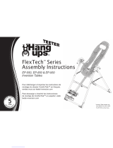
IMPORTANT SAFETY INSTRUCTIONS
READ ALL INSTRUCTIONS BEFORE USING THE INVERSION TABLE.
WARNING
!
SAVE THESE INSTRUCTIONS
WARNING - To reduce the risk of injury to persons:
• Read and understand all the instructions, view the instructional video, review all other accompanying documents, and inspect the
equipment before using the inversion table. It is your responsibility to familiarize yourself with the proper use of this equipment and the
inherent risks of inversion, such as falling on your head or neck, pinching, entrapment, or equipment failure. It is the responsibility of
the owner to ensure that all users of the product are fully informed about the proper use of the equipment and all safety precautions.
•
Close supervision is necessary when the inversion table is used near children, or by or near invalids or disabled persons.
• Use the inversion table only for its intended use as described in this manual. DO NOT use attachments not recommended by the
manufacturer.
• NEVER drop or insert any object into any opening.
• DO NOT use or store product outdoors.
• DO NOT use if you are over 6 ft 6 in (198 cm) or over 300 lbs. (136 kg). Structural failure could occur or head/neck may impact the
oor during inversion.
• DO NOT allow children to use this machine.
• Keep children, bystanders, and pets away from machine while in use.
• Keep body parts, hair, loose clothing and jewelry clear of all moving parts.
• The inversion table has no user serviceable parts.
• This product is intended for indoor home use only. DO NOT use in any commercial, rental or institutional setting.
FAILURE TO FOLLOW INSTRUCTIONS AND WARNINGS COULD RESULT IN SERIOUS INJURY OR DEATH.
BEFORE YOU BEGIN: Review all steps before beginning assembly and read all precautions before using the inversion table.
Carefully adhere to the Assembly Instructions and Owner’s Manual to help ensure safety and product integrity.

IMPORTANT SAFETY INSTRUCTIONS
READ ALL INSTRUCTIONS BEFORE USING THE INVERSION TABLE.
WARNING
!
SAVE THESE INSTRUCTIONS
FAILURE TO FOLLOW INSTRUCTIONS AND WARNINGS COULD RESULT IN SERIOUS INJURY OR DEATH.
BEFORE YOU BEGIN: Review all steps before beginning assembly and read all precautions before using the inversion table.
Carefully adhere to the Assembly Instructions and Owner’s Manual to help ensure safety and product integrity.
• DO NOT use the equipment without a licensed physician’s approval and a review of the medical contraindications, as noted in the
Owner’s Manual.
• Failure to assemble and/or use the equipment as directed may void the manufacturer’s warranty on this product and could result in
injury or death.
• Choose a level surface for assembling and operating the table.
• Follow each step in sequence. DO NOT skip ahead.
• Make sure that all fasteners are secure.
• ALWAYS test and inspect the table. Make sure the table rotates smoothly to inverted position and back.
• ALWAYS replace defective components immediately and/or keep the equipment out of use until repair.

Items are not shown to scale. If you have any questions on assembly, contact Customer Service
at 1-800-847-0143 or visit our website at teeter-inversion.com.
Items for Assembly
F5-1050
F5-1045 H1-3010
H1-1212
F5-1065
A-Frame
Stability Feet (2)
May come pre-assembled
FitFlexTM Table Bed
Upper Bed Portion
Lower Bed Portion & Frame
Bolts & Nuts (3)
FitFlexTM Bed Frame Extension
Accessories
Head Pillow
Decompression ArchTM
Angle Tether
IA-2500
IA-1101
F1-1300
F1-1300A
F1-1300B
F1-1390
F1-1380
EP-1105
IA-1650
F5-1007
ITEMS FOR ASSEMBLY ITEM NUMBER
Main Shaft
with T-Pin Ankle Lock System
Front Ankle Bar with Foam Rollers
Bolt
Nut
End Cap
IA-1600
F5-1045
H1-1212
H1-3010
F5-1050
ITEMS FOR ASSEMBLY ITEM NUMBER
Handle Assembly
Traction SupportTM Handles (2)
Bolts & Nuts (2)
Bolts/Nuts may come pre-assembled in Handles
Hinge Covers (2)
Allen Bolts (4)
Allen Bolts may come pre-assembled in Hinge Covers
Roller Hinge Assembly
3-Hole Roller Hinges (2)
Tools
10/13mm Wrenches (2)
5mm Allen Wrench
IA-1670
IA-1148B
F1-1250
F5-0071
F5-1065
F5-1088
IA-1149
ITEMS FOR ASSEMBLY ITEM NUMBER
EP-1105 IA-1650 F5-1007
F1-1300B
IA-2500
F1-1300A F1-1390
F1-1380
IA-1101
IA-1670 IA-1148B F1-1250 F5-0071
IA-1600
IA-1149
F5-1088
Other Tools Required for Assembly: Scissors or Snips

9
13
10
7
3
11
4
6
2
1
5
*Inversion Table images may vary slightly from your model.
Before reading further, study the drawing below to familiarize yourself with the
important components of your new Teeter Hang Ups® 600ia™ Inversion Table.
Before Beginning
Head Pillow
Bed Frame Extension
FitFlex™ Table Bed
3-Hole Roller Hinges
Traction Support™ Handles
Height-Selector Locking Pin
Spreader Arms
Angle Tether
Crossbar
A-Frame
Main Shaft
Ankle Lock System
Ankle Comfort Dial™
Stability Feet
Decompression Arch™
1
2
3
4
5
6
7
8
9
10
11
12
13
14
15
8
12
14
15

WARNING LABEL PLACEMENT
Important: Please review all labels and supporting materials before using your inversion table.
We hope you enjoy your new Teeter Hang Ups Inversion Table!
If you have any questions, please contact our Customer Service Department at 1.800.847.0143 or www.teeter-inversion.com.
This drawing indicates the locations of the warning
labels found on your product.
If a label is missing, illegible or is removed,
contact Customer Service at the phone number or
website found at the bottom of this page to request a
complimentary replacement label.
Note: Image and labels below not shown actual size.
WARNING - To reduce the risk of personal injury or death:
•
Read and understand all the instructions before using the inversion table.
It is your responsibility to familiarize yourself with the proper use of the
equipment and the inherent risks of inversion, such as falling on your head
or neck, pinching, entrapment or equipment failure.
•
Do not allow children to use the machine.
•
Keep children, bystanders, and pets away from the machine while in use.
•
Keep body parts, hair, loose clothing and jewelry clear of all moving parts.
•
Height/Weight capacity: 4 ft 8 in - 6 ft 6 in (142-198 cm); 300 lbs (136 kgs).
•
This product is for consumer, indoor household use only.
Replace Labels and Owner’s Manual if Damaged, Illegible, or Removed.
Teeter, 9902 162nd St. Ct. E., Puyallup, WA 98375
Toll Free (Phone): 800-847-0143 Web: www.teeter-inversion.com
WARNING
!
EP-1737 0911-3
WARNING
!
IA-2007 0611-1
Ankles must be properly
secured before use.
REPLACE LABEL
IF DAMAGED, ILLEGIBLE,
OR REMOVED.
WARNING
!
E6-1740 0711-0
Do not use Setting A
for users over
220 lbs (100 kgs).
REPLACE LABEL
IF DAMAGED, ILLEGIBLE,
OR REMOVED.
! WARNING
TIPPING HAZARD: For upright storage, leave A-Frame open wide enough
to remain stable, or secure to the wall to prevent tipping. In households with
small children, the table should be stored flat on the floor, not upright.
NX-1720 0910-2
REPLACE LABEL IF DAMAGED, ILLEGIBLE, OR REMOVED.

Step 1
Assemble the Table Bed (F1-1300) and Bed Frame Extension (F1-1380)
NOTE: This assembly will be referred to as Table Bed (F1-1300) for the remainder of
the Assembly Instructions.
• Locate the following items to assemble the FitFlex Table Bed:
Upper Portion (F1-1300A) Lower Portion & Frame (F1-1300B)
Bed Frame Extension (F1-1380) Bolts & Nuts (F1-1390)
5mm Allen Wrench (IA-1149) 10/13mm Wrench (F5-1088)
• Lay the Upper Portion (F1-1300A) face down on the floor.
• Place the Lower Portion & Frame (F1-1300B) face down on top of the Upper Portion and
align the bolt holes (Figure 1).
• Reaching underneath, insert the longest of the three bolts into the Center hole and
hand-tighten with a Nut.
• Reaching underneath, insert one of the shorter bolts through a Top hole in the Upper
Portion and hold in place. Slide one of the Bed Frame Extension loops over the Bolt and
hand-tighten with a Nut (Figure 2).
• Repeat with the remaining side (Figure 3).
• To fully tighten all three nuts to the bolts, insert the 5mm Allen Wrench (IA-1149) into the
Bolt heads and tighten the Nuts using the 10/13mm Wrench (F5-1088).
FIGURE 1
Upper Bolts (2)
Lower Bolt (1)
FIGURE 3
1
2
Upper Bolts (2)
FIGURE 2
2Loop
Bolt
1

Step 2
Assemble the front Stability Feet (IA-1101) onto the A-Frame (IA-2500)
Feet may come pre-assembled.
• Steady both sides of the A-Frame so that the legs will not swing open and turn the A-Frame
so that the base points upwards. This will give you downward leverage to secure the Stability
Feet (Figure 4).
• Determine which is the Right and Left Stability Foot by the imprinted letters “R” and “L”,
found on each foot. You will place each foot on the frame legs so that the letters face inward
towards each other.
• Select the Stability Foot labeled “R” on the inside and insert it on the RIGHT side of the
A-Frame (Figure 4).
• Repeat with the Stability Foot labeled “L” on the LEFT side (Figure 4).
• Open the A-Frame on the floor (Figure 6) and make sure the Spreader Arms are locked
open.
• Familiarize yourself with the Front, Back, Left and Right of the A-Frame. You may want to
refer back to this diagram for reference throughout the assembly process.
Right
Left
FIGURE 4
FIGURE 5
Back
Front
2
1
Right Left
FIGURE 6
2Crossbar
Spreader Arms
1

Step 3
Assemble the 3-Hole Roller Hinges (F5-1065) to the Table Bed (F1-1300)
• For ease-of-assembly, rest the Table Bed against the Crossbar (Figure 7).
• Open the Cam Locks on each side of the Table Bed (Figure 8).
• With the Pivot Pins facing outward, insert the Roller Hinges into the brackets on each side
of the Table Bed Assembly. The Roller Hinges must slide between the Cam Locks and the
Brackets (Figure 8).
• Engage one of the holes in the Roller Hinge over the Bracket Pin. Make sure the Roller
Hinges are in the same hole setting on both sides. Figure 9 shows the Roller Hinges
engaged correctly in Setting C.
• Push down on the Cam Locks (Figure 10) to secure the Roller Hinges.
NOTE: Refer to the Owner’s Manual for an explanation of the hole settings.
If you are unsure, use Setting C to start.
Unlocked Locked
FIGURE 10
C
B
A
1
2
3
FIGURE 9
FIGURE 8
FIGURE 7
2Bracket Pin
Pivot Pin
1
3Cam Lock

Step 4
Attach the Table Bed (F1-1300) to the A-Frame (IA-2500)
• Pick up the Table Bed, holding each side near the Roller Hinges, and stand in front of the
A-Frame where the Crossbar is located (refer to Figure 6 to determine A-Frame Front).
• Lower each Roller Hinge Pivot Pin into the A-Frame hinge plates, one side at a time
(Figures 11 and 11A).
NOTE: You may need to push outward on the A-Frame in order for the second Pivot Pin
to lock in place.
• Make sure that each Pivot Pin is seated at the base of the slot of the Hinge Plate (Figure 12).
• Ensure that the Self-Locking Hooks have closed over both Pivot Pins, and that the Table
Bed rotates smoothly.
WARNING
!
Failure of the Self-Locking Hooks to close over both Roller Hinge
Pivot Pins is an indication of improper assembly and if not corrected
could result in serious injury or death!
2Self-Locking Hook
Roller Hinge Pivot Pin
1
2
FIGURE 11
FIGURE 11A
FIGURE 12
1
1
2
2Roller Hinge
Self-Locking Hook
1

Step 5
Install the Front Ankle Bar Assembly (F5-1045) into the Main Shaft (IA-1600)
• Insert the Front Ankle Bar (F5-1045) into the Front Ankle Bar Housing (Figure 13). Pull up
on the T-Pin Lock to insert the Front Ankle Bar all the way and release in the shortest setting
(the hole closest to the Front Ankle Bar).
• From the reverse side, pull on the zip-tie to stretch the Retainer Spring and Cable Loop so
that they align with the hole at the back of the Front Ankle Bar Housing (Figure 14).
• Insert the Bolt (H1-1212) through the hole, Retainer Spring, Cable Loop, and the hole on the
other side of the housing (Figure 14A).
• Tighten the Nut (H1-3010) using the 13mm Open Wrench (F5-1088) provided.
• Cut the long portion of the zip-tie with scissors and cover the open end with the End Cap
(F5-1050) (Figure 14B).
WARNING
!
Failure to assemble the T-Pin Ankle Lock System properly could
result in serious injury or death!
1
FIGURE 14
FIGURE 14A
FIGURE 14B
1
FIGURE 13
VIEWS FROM BACK
1Retainer Spring & Cable Loop
Front Ankle Bar Housing
1

Step 6
FRONT
1
23
1
2
Insert the Main Shaft (IA-1600) into the Table Bed (F1-1300)
• With the Height Adjustment Settings on the Main Shaft facing up, slide the end of the Main
Shaft into the Main Shaft Housing (Figure 15) on the Table Bed.
• Pull out the Height-Selector Locking Pin to allow the Main Shaft to slide in further and
release in the desired height setting. Refer to the Owner’s Manual for more information on
selecting your height setting.
• The Main Shaft MUST REST against the Crossbar of the A-Frame (Figure 16).
NOTE: The Crossbar prevents the Table Bed from rotating forward when the user steps on
the Ankle Comfort Dial. If the Main Shaft does not rest on the Crossbar as shown in Figure
16, then the Table Bed has been assembled backwards onto the A-Frame. This MUST BE
CORRECTED before use.
FIGURE 15
FIGURE 16
2Main Shaft Housing
Main Shaft
1
3Height-Selector Locking Pin
2Crossbar
Proper Resting Position
1

WARNING
!
If your Teeter Hang Ups Inversion Table looks like either of these images,
your table has been misassembled and is unt for use.
Improper assembly could result in serious injury or death!
We hope you enjoy your new Teeter Hang Ups Inversion Table!
If you have any questions, please contact our Customer Service Department at 1.800.847.0143 or www.teeter-inversion.com.
Image B
Go back to Step 5 for instruction.
Demonstrates that the Table Bed has been assembled
into the A-Frame backwards and must be corrected.
Image A
Go back to Step 4 for instruction
Demonstrates that the Roller Hinges have been assembled
upside down into the Table Bed and must be corrected.

Step 7
Assemble the Traction SupportTM Handles (IA-1670) to the A-Frame (IA-2500)
Bolts/Nuts may come pre-assembled in the Handles. Simply unscrew to remove.
• Insert the Left and Right handles into the A-Frame (Figure 17), so that the long part of the
handles are parallel with the rear legs of the A-Frame.
• Insert the Bolt (IA-1148B) from the inside through the Hinge Plate into the Handle.
Hand tighten with the nut on the outside of the Hinge Plate (Figure 18).
• Secure using the 10/13mm Wrench (F5-1088) provided, being careful not to overtighten.
• Repeat on the other side.
Attach the Hinge Covers (F1-1250) to the Hinge Plates
Allen Bolts may come pre-assembled in the Hinge Covers. Simply unscrew to remove.
• Align the Left and Right Hinge Covers with the corresponding shape of the Hinge Plate on
either side of the A-Frame (Figure 19).
• Insert two (2) Allen Bolts (F5-0071) through the Hinge Plate into the Hinge Cover.
• Tighten with the Allen Wrench (IA-1149) provided, being careful not to overtighten.
• Repeat on the other side.
FIGURE 17
FIGURE 18
1
2
FIGURE 19
2Allen Bolts
Hinge Cover
1

Step 8
Assemble the Angle Tether (F5-1007) to the Table Bed (F1-1300)
• The Tether will come pre-assembled to the A-Frame.
• Unfold the adjustable Tether and clip it to the U-Bar on the underside of the Table Bed
(Figure 20).
Attach the Head Pillow (EP-1105)
• Attach the Head Pillow by inserting the Velcro Straps through the holes in the Table Bed
and securing the ends together (Figure 21). The position of the pillow can be adjusted
depending on the user.
FIGURE 20
FIGURE 21

Before Use
• Test the Inversion Table by hand for smooth and steady rotation (Figure 22).
• Ensure that all fasteners are secure.
• Please complete the warranty registration online at www.teeter-inversion.com.
• For your reference, the serial number can be found on the back of the Table Bed.
WARNING
!
Read the Owner’s Manual thoroughly before using your Teeter Hang Ups
Inversion Table. Improper settings could result in serious injury or death!
FIGURE 22 Step 9

Adjustments: Changing the Roller Hinge Setting
To adjust the Roller Hinge setting, you’ll need to fully remove the Table Bed from the A-Frame.
• Remove the Angle Tether from the U-Bar located on the underside of the Table Bed.
• Pull the Height-Selector Locking Pin and slide the Main Shaft in all the way to the last hole
setting.
• Release and engage the Pin in the storage setting.
• Rotate the Table Bed opposite from use until it has turned 180 degrees and rests against
the Crossbar of the A-Frame (Figure 23).
• With palms up, reach under and around each Roller Hinge, using your thumbs to release
the locks over the Pivot Pin (Figure 24).
• Lift both sides of the Table Bed out of the A-Frame at the same time. TIP: Rest the head
of the Table Bed on the floor for quick adjustment.
• Unlock the Cam Locks for each Roller Hinge. Change the Roller Hinges to the desired
setting (A, B or C).
NOTE: Refer to the Owner’s Manual for more information on finding your Roller Hinge Setting.
• Re-lock the Cam Locks (Figure 25). Replace the Roller Hinges into the hinge plates of the
A-Frame.
• Rotate the Table Bed back to the use position and re-adjust the Main Shaft height settings
for use.
Adjusting the Roller Hinge Setting
B
FIGURE 25
A C
FIGURE 24
FIGURE 23

Maintenance
• To clean the Inversion Table, wipe down with a damp cloth. Do not use abrasive
cleaners or solvents.
Storage
• Remove the Angle Tether from the U-Bar located on the underside of the Table Bed.
• Pull the Height-Selector Locking Pin and slide the Main Shaft in all the way to the
last hole setting.
• Release and engage the Pin in the storage setting.
• Rotate the Table Bed opposite from use until it has turned 180 degrees and rests against
the Crossbar of the A-Frame.
• Pull up on the Spreader Arms to fold the A-Frame (Figure 26), leaving the A-Frame legs
open to a width of 12” for stability.
NOTE: This operation may pinch fingers if not done slowly and carefully.
Maintenance/ Storage
Tipping Hazard: For upright storage, leave A-frame open wide
enough to remain stable, or secure to the wall to prevent tipping.
In households with small children, the inversion table should be stored
at on the oor, not upright.
WARNING
!
FIGURE 26

U.S. and Foreign Patents Pending. Teeter Hang Ups is a registered trademark of Teeter.
Specications subject to change without notice.
© COPYRIGHT 2012 Teeter. International Law Prohibits Any Copying.
L1-6001 1212-1
Any modication to
this device will void
the UL Listing.
MDSS GmbH
Schiffgraben 41
30175 Hannover, Germany
EC REP
If you have any problems assembling the equipment, or questions about its use, please contact customer service at:
USA: Teeter
Toll Free (Phone) 800-847-0143
(Fax) 800-847-0188
www.teeter-inversion.com
International: Inversion International, Ltd.
(Phone) +1-242-362-1001
(Fax) +1-242-362-1002
www.InversionInternational.com
/