
Important
Read this document before operating / installing this product
For additional product manuals and operation / installation procedures, please visit www.AquaCal.com
AquaCal®
Installation Manual
AND
LTP0101 REV 2d


Table of Contents
Contacting AquaCalAutoPilot, Inc. 1
Safety Instructions 1
1 - Installation 3
1.1 Dimensions 3
1.2 Positioning Equipment 4
1.3 Clearances 5
1.4 Plumbing 6
1.4.a Plumbing Requirements 6
1.4.b Water Source Plumbing Diagrams 7
1.4.c SunPower Plumbing Diagrams 10
1.4.d Water Connections to Heat Pump 11
1.4.e In-Line Chlorine Feeders 13
1.4.f Water Flow Rates 14
1.4.g Adjusting Water Flow Using ΔT (Delta-T) 15
1.4.h Maintaining Ability to Winterize 16
1.4.i Adjusting Water Pressure Switch 16
1.5 Electrical 17
1.5.a Electrical Requirements 17
1.5.b Incoming Power Access Holes 20
1.5.c Access Panels 21
1.5.d Verifying Transformer Setting 21
1.5.e Three-Phase Adjustment 22
1.5.f Schematics 22
1.5.g Connecting an External Controller 23
1.5.h Programming for an External Controller 24
1.6 Service Level Programming 26
1.6.a Service Level Factory Defaults 26
1.6.b Enter Service Level Programming 27
1.7 Cleaning Equipment After Installation 29
2 - Operation 31
2.1 Energizing Heat Pump 31
2.2 Wake Up Heat Pump 31
2.3 Display Panel 31
2.3.a Buttons 31
2.3.b Display 31
2.3.c Indicator Lights 32
2.4 User Level Programming 32
i

2.4.a User Level Factory Defaults 32
2.4.b Selecting Celsius or Fahrenheit 34
2.4.c Setting Operating Mode 34
2.4.d Setting Thermostats 35
2.4.e User Lock Option (Enable) 35
2.4.f User Lock Option (Disable) 36
2.4.g Using Pass Code to Access Heat Pump 36
2.4.h Operating Heat Pump (With an External Controller) 37
3 - Maintenance 38
3.1 Water Chemistry 38
3.2 Planned Maintenance 38
3.3 Winterizing 39
4 - Appendix 42
4.1 Identifying Model Specifications 42
4.2 Weights 43
4.3 Heating Recommendations 43
4.4 Cooling Recommendations 43
4.5 Available Accessories 44
4.6 Schematics 46
Schematic LTM0196 47
Schematic LTM0739 48
Schematic LTM0738 49
Schematic LTM0738 50
Schematic LTM0739 51
5 - Troubleshooting 52
5.1 Fault Codes 52
5.2 Issues and Resolutions 55
ii

Page - 1
Contacting AquaCalAutoPilot, Inc.
For further assistance, please contact the distributor or installer of this product.
If unavailable, please contact AquaCal®for a partner in your area. To better assist you, please have the heat
pump model and serial number available. See "Identifying Model Specifications" on page 42.
Product Information:
Website www.AquaCal.com
Phone (1) 727-823-5642
Hours 8-5 pm, Eastern M-F
Service Information:
Website www.AquaCal.com/request-heat-pump-service/
SAFETY INSTRUCTIONS
lFor personal safety, and to avoid damage to equipment, follow all safety instructions displayed on the equipment
and within this manual. Repair and service of heat pump must be performed by an authorized service center.
lWarranties may be voided if the equipment has been improperly installed, maintained or serviced.
lIf service is deemed necessary, please see "Contacting AquaCalAutoPilot, Inc." on page 1.
SAFETY SIGNALS
Throughout this document, safety signals have been placed where particular attention is
required.
DANGER - Failure to heed the following will result in injury or death.
WARNING Failure to heed the following may result in injury or death.
NOTICE Failure to heed the following may result in damage to equipment.
When installing and using your heat pump basic safety precautions must always be followed, including the
following:
DANGER - Failure to heed the following will result in injury or death.
lThe heat pump utilizes high voltage. Use caution when servicing.

Page - 2
WARNING Failure to heed the following may result in injury or death.
lInstallation and repairs must be performed by a qualified technician.
lThe heat pump contains refrigerant under pressure. Repairs to the refrigerant circuit
must not be attempted by untrained and / or unqualified individuals. Service must
be performed only by qualified HVAC technicians. Recover refrigerant before
opening the system.
lImproper water chemistry can present a serious health hazard. To avoid possible
hazards, maintain pool / spa water per standards detailed in this document.
lProlonged immersion in water warmer than normal body temperature may cause a
condition known as Hyperthermia. The symptoms of Hyperthermia include
unawareness of impending hazard, failure to perceive heat, failure to recognize the
need to exit the spa, and unconsciousness. The use of alcohol, drugs, or medication
can greatly increase the risk of fatal Hyperthermia. In addition, persons having an
adverse medical history, or pregnant women, should consult a physician before
using a hot tub or spa. Children and the elderly should be supervised by a
responsible adult.
lProlonged immersion in water colder than normal body temperature may cause a
condition known as Hypothermia. The symptoms of Hypothermia include shivering
(although as hypothermia worsens, shivering stops), clumsiness or lack of
coordination, slurred speech or mumbling, confusion and poor decision-making,
drowsiness or low energy, lack of concern about personal welfare, progressive loss
of consciousness, weak pulse and slow or shallow breathing. In addition, persons
having an adverse medical history, or pregnant women, should consult a physician
before immersing in a cold body of water. Children and the elderly should be
supervised by a responsible adult.
NOTICE Failure to heed the following may result in damage to equipment.
lMaintain proper water chemistry in order to avoid damage to pump, filter, pool
shell, etc.
lWater flow exceeding maximum flow rate requires a bypass. Damage due to
excessive water flow will void warranty.
SAVE THESE INSTRUCTIONS

Page - 3
1 - Installation
WARNING Failure to heed the following may result in injury or death.
lInstallation of this equipment by anyone other than a qualified installer can result in
a safety hazard.
lThe information contained throughout the "Installation" section is intended for use
by qualified installation technicians familiar with the swimming Pool / Spa safety
standards.
NOTICE Failure to heed the following may result in damage to equipment.
lFailure to protect equipment against corrosive conditions will adversely affect the
life of the equipment and will void equipment warranty.
1.1 Dimensions
(Water Source WS03, WS05)

Page - 4
(Water Source WS10)
(SunPower SP05)
1.2 Positioning Equipment
Controlling Irrigation and Rainwater Runoff
lIrrigation water may damage heat pump components. Direct irrigation water away from the heat pump.
lThe heat pump will withstand normal rainfall. Do not allow a roof slope to direct rainwater onto the heat pump.
Have a gutter installed on the roof edge to direct this water away from the heat pump. Or install the heat pump in
another location.

Page - 5
Mounting Pad Requirements
lBuild the heat pump pad out of concrete or other code-approved material.
lConfirm the pad can support the weight of the heat pump. See "Weights" on page 43.
lElevate the pad enough to allow for drainage.
lMake sure the pad is flat and level.
lHave the pad extend at least 6 inches from the heat pump base in all directions.
lDo not install the heat pump on soil or grass.
lDo not allow the heat pump base to touch the building's foundation.
lDo not place the heat pump directly on a concrete floor. This can case noise to be transmitted to an occupied
space. If necessary install vibration dampers between the heat pump base and floor.
lEquipment pad must meet all requirements of authorities having code-related jurisdiction.
Anchoring to Pad
lFollow all applicable local, state, and national requirements regarding wind load anchoring.
lThe shipping brackets used to secure the heat pump to the pallet are approved mounting (hurricane) brackets.
They should be used to anchor the heat pump to the pad.
lIf needed, contact AquaCal®to obtain anchoring kit information. Please have the heat pump model number and
serial number when requesting support. See "Identifying Model Specifications" on page 42.
1.3 Clearances
lLocate the heat pump at least 24 inches away from the wall. And provide a minimum 24 inches between heat
pumps. This will allow for rear plumbing access and electrical connections.
lDo not stack heat pumps on top of each other. Use approved racks when stacking equipment.
lOnly rack equipment two units high.
lEquipment rack must meet all requirements of authorities having code-related jurisdiction.
lAvoid storing chemical containers near the heat pump. The chemicals can cause equipment damage.
lAvoid placing objects near or on top of the heat pump. This includes shrubbery and lawn furniture. These objects
will reduce performance and efficiency and hinder maintenance access.
Water Source (Top View) Water Source (Side View)

Page - 6
1.4 Plumbing
1.4.a Plumbing Requirements
NOTICE Failure to heed the following may result in damage to equipment.
lDo not use glue on the threaded portion of the equipment’s unions. A glued-in-
place union will prevent the equipment from being properly winterized.
lThe heat pump must receive water flow within the specified minimum ranges under
worst-case conditions such as a fouled water filter.
lFailure to provide clean filtered water to the heat pump can void product warranty.
lWater flow exceeding maximum flow rates will negatively affect the total pool
filtration performance and may damage the heat pump. This will not be covered
under equipment warranty. See "Water Flow Rates" on page 14.
lTemperature ports with PVC tees and a test thermometer are also provided in
selected models. These ports must be installed between the unions and the bypass
valves. The preferred location of the port is 6" from the heat pump union. See
"Adjusting Water Flow Using ΔT (Delta-T)" on page 15.
lUsing open saltwater applications as the heat pumps source water is not
recommended.
lSaltwater can promote the growth of crustaceans, which can clog a heat
pump’s heat exchanger. These types of applications are highly problematic and
require additional maintenance.
lIf a saltwater source is unavoidable, install an external plate heat exchanger to
protect the heat pump from fouling. Please note – Saltwater wells do not
require an external plate heat exchanger.

Page - 7
1.4.b Water Source Plumbing Diagrams
Plumbing diagrams are provided in this section as a planning guide to the sequence of equipment, valves, and
fittings.
lThe basic plumbing configurations for typical installations are shown.
lIf the installation does not closely follow any of the supplied plumbing diagrams, AquaCal®Technical Support is
available for installation advice and guidance.
lConfirm water provided to heat pump is clean and filtered.
It's important to use contractors familiar with geothermal applications when installing a
Water Source heat pump.
Single Water Source Heat Pump Configuration (Standard Pressures)
Multiple Water Source Heat Pump Configuration (Standard Pressures)

Page - 8
Single Water Source Heat Pump Configuration (High-Pressure)
Multiple Water Source Heat Pump Configuration (High-Pressure)

Page - 9
Water Source Heat Pump with Support Equipment
Water Source Heat Pump (Reverse Return Detail)

Page - 10
1.4.c SunPower Plumbing Diagrams
Plumbing diagrams are provided in this section as a planning guide to the sequence of equipment, valves, and
fittings.
lThe basic plumbing configurations for typical installations are shown.
lIf the installation does not closely follow any of the supplied plumbing diagrams, AquaCal®Technical Support is
available for installation advice and guidance.
lConfirm water provided to heat pump is clean and filtered.
Typical SunPower Installation
Dedicated Spa Heater using Pool as the Heat Source.
PLEASE NOTE -
The SunPower is designed to provide heating for a spa. Not a pool.

Page - 11
SunPower Heat Pump Configuration
1.4.d Water Connections to Heat Pump
lHeat Pump union sizes are specified on diagrams.
lConnections to site plumbing are made via PVC solvent cement to the female slip socket of the plumbing unions.
lHigh-pressure units use joint compound on threaded copper connections. See "Single Water Source Heat Pump
Configuration (High-Pressure)" on page 8.
lPlumbing unions are available from AquaCal®.See "Available Accessories" on page 44.
NOTICE Failure to heed the following may result in damage to equipment.
lDo not use glue on the threaded portion of the equipment’s unions. A glued-in-
place union will prevent the equipment from being properly winterized.

Page - 12
Water Source WS10 (Titanium or Cupronickel Exchanger)
Water Source WS03 and WS05 (Titanium Exchanger Only)
Water Source WS03 and WS05 (Titanium / Cupronickel Exchanger Combination)

Page - 13
SunPower SP05 (Titanium Exchanger Only)
SunPower SP05 (Titanium / Cupronickel Exchanger Combination)
1.4.e In-Line Chlorine Feeders
Place in-line chlorinators downstream from the heat pump and as low in elevation as possible. If an erosion
type feeder is used, always install a Hartford Loop to protect internal heat pump components.
Heat Pump with Hartford Loop

Page - 14
1.4.f Water Flow Rates
Maintain water flow rates as indicated. Please note, these specifications relate to the heat pump only. Code-
specified whole system turnover rates must be satisfied.
NOTICE Failure to heed the following may result in damage to equipment.
lWater flow exceeding maximum flow rates will negatively affect the total pool
filtration performance and may damage the heat pump. This will not be covered
under equipment warranty.
Water Source
MODEL SOURCE HEAT EXCHANGER
TYPE
FLOW RATES
MINIMUM MAXIMUM
WS03
Source-Side Titanium ThermoLink®20 GPM 70 GPM
Cupronickel 10 GPM 14 GPM
Pool / Spa Titanium ThermoLink®30 GPM 70 GPM
Cupronickel N/A N/A
WS05
Source-Side Titanium ThermoLink®20 GPM 70 GPM
Cupronickel 10 GPM 18 GPM
Pool / Spa Titanium ThermoLink®30 GPM 70 GPM
Cupronickel N/A N/A
WS10
Source-Side Titanium ThermoLink®30 GPM 70 GPM
Cupronickel 30 GPM 54 GPM
Pool / Spa Titanium ThermoLink®30 GPM 70 GPM
Cupronickel N/A N/A
SunPower
MODEL SOURCE HEAT EXCHANGER
TYPE
FLOW RATES
MINIMUM MAXIMUM
SP05 Spa-Side Titanium ThermoLink®20 GPM 45 GPM
Pool-Side Titanium ThermoLink®30 GPM 70 GPM
PLEASE NOTE -
If minimum flow rates are not met, heat pump performance is reduced and performance will
suffer. Internal safety devices may deactivate the heat pump with the following errors:
lHP and HP5
lor (if equipped) error codes of LP and LP5
lOperate water filtration devices per manufacturer's specifications. Dirty filters can cause a reduction of water flow
to the heat pump. An increase of 7-10 psi higher than the clean filter pressure typically reduces flow rates. This

Page - 15
requires the filter to be cleaned or back-washed.
lKeep baskets free of debris. A large quantity of debris in the pump and skimmer baskets can reduce water flow.
lCheck for improper valve settings. A partially closed valve after the filter, or a full-open bypass around the heat
pump, will cause insufficient water flow through the heat pump.
lThe maximum static pressure (or operating pressure) is 50 pounds-per-square-inch (PSI) unless a special "high-
pressure" unit has been ordered. These specifications relate to the heat pump only.
lCode-specified whole system turnover rates must be satisfied.
1.4.g Adjusting Water Flow Using ΔT (Delta-T)
The Delta-T is the temperature difference between the water temperatures entering and leaving the heat pump.
The equipment can be fine-tuned for maximum performance by balancing water flow rates to maintain an
ideal ∆T.
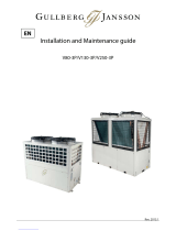
lInstalled temperature ports are required to perform the following procedures.
lThis adjustment procedure must be completed with the unit in heating mode.
PLEASE NOTE -
lThe installation of temperature ports are required for all Water Source and SunPower heat
pumps on both inlet and outlet piping.
lSee "Temperature Port Kit" on page 45.
Temperature Port
(Shown with Probe)
1. Adjust thermostat to its lowest setting with unit in heating
mode.
2. Deactivate the water filtration pump.
3. Confirm that the filters leading to the heat pump are clean.
4. Adjust the valves controlling water headed towards the heat
pump to the half open position.
5. Adjust the valves controlling water leading away from the
heat pump to a fully open position.
6. Activate the pool water filtration pump.
7. Slowly raise the thermostat temperature until the heat pump
activates.
lThe source-water filtration pump will cycle on first.
lAfter a four-minute delay, the heat pump's compressor
will start.
8. With the heat pump running, confirm the source-side water filtration pump is operating properly with adequate
flow and no short cycling.
9. Wait for water temperatures to stabilize (approximately 5 minutes).
10. Adjust valves in the following order:
a. Adjust the source-side valve that controls water exiting the heat pump. Match the temperature measured with a
temperature probe to the temperature chart.
b. Adjust the pool-side valve that controls water exiting the heat pump. Match the temperature measured with a
temperature probe to the chart. (See "Temperature Chart" in this section)
c. Wait for water temperatures to stabilize. Then check source-side temperature again. Re-adjust the valve
controlling the water exiting the heat pump as needed.
d. Wait for water temperatures to stabilize. Then check pool-side temperature again. Re-adjust the valve
controlling the water exiting the heat pump as needed.
11. Mark valves at these positions for future reference.

Page - 16
HEAT EXCHANGER
TYPE MODEL POOL-SIDE SOURCE-SIDE
Titanium pool-side and
source-side exchangers
WS03 2° to 4° F 1° to 5° F
WS05 3° to 6° F 2° to 8° F
WS10 6° to 14° F 5° to 12° F
Titanium pool-side
exchanger and
cupronickel source-side
exchanger
WS03 1° to 3° F 6° to 8° F
WS05 2° to 6° F 7° to 13° F
WS10 6° to 14° F 6° to 11° F
Titanium ThermoLink®SP05 3° to 6° F 2° to 8° F
Table 1 - Temperature Chart
PLEASE NOTE -
lTemperature differences are based on pool and source water water temperatures of 69° to 75°
F.
lFor water temperatures outside this range, contact AquaCal®.See "Contacting
AquaCalAutoPilot, Inc." on page 1.
1.4.h Maintaining Ability to Winterize
Do not glue the threaded portion of the unions. The unions are used to decouple the heat pump from the
plumbing system during hard freeze conditions.
NOTICE Failure to heed the following may result in damage to equipment.
lDo not use glue on the threaded portion of the equipment’s unions. A glued-in-
place union will prevent the heat pump from being properly winterized.
1.4.i Adjusting Water Pressure Switch
Adjust water pressure switch when heat pump attempts to operate without water flow.
Before attempting any adjustments confirm the
following :
lThe filter is clean.
lFilter pump is operating.
lThe valves are set to direct the appropriate amount
of water through the heat pump. See "Water Flow
Rates" on page 14.
lFLO is displayed (or displays intermittently).
WARNING Failure to heed the following may result in injury or death.
lWater Pressure Switch adjustment procedure to be performed by experienced
service personnel only; procedure must not be attempted by individuals lacking
adequate electrical and mechanical experience.
Page is loading ...
Page is loading ...
Page is loading ...
Page is loading ...
Page is loading ...
Page is loading ...
Page is loading ...
Page is loading ...
Page is loading ...
Page is loading ...
Page is loading ...
Page is loading ...
Page is loading ...
Page is loading ...
Page is loading ...
Page is loading ...
Page is loading ...
Page is loading ...
Page is loading ...
Page is loading ...
Page is loading ...
Page is loading ...
Page is loading ...
Page is loading ...
Page is loading ...
Page is loading ...
Page is loading ...
Page is loading ...
Page is loading ...
Page is loading ...
Page is loading ...
Page is loading ...
Page is loading ...
Page is loading ...
Page is loading ...
Page is loading ...
Page is loading ...
Page is loading ...
Page is loading ...
Page is loading ...
Page is loading ...
-
 1
1
-
 2
2
-
 3
3
-
 4
4
-
 5
5
-
 6
6
-
 7
7
-
 8
8
-
 9
9
-
 10
10
-
 11
11
-
 12
12
-
 13
13
-
 14
14
-
 15
15
-
 16
16
-
 17
17
-
 18
18
-
 19
19
-
 20
20
-
 21
21
-
 22
22
-
 23
23
-
 24
24
-
 25
25
-
 26
26
-
 27
27
-
 28
28
-
 29
29
-
 30
30
-
 31
31
-
 32
32
-
 33
33
-
 34
34
-
 35
35
-
 36
36
-
 37
37
-
 38
38
-
 39
39
-
 40
40
-
 41
41
-
 42
42
-
 43
43
-
 44
44
-
 45
45
-
 46
46
-
 47
47
-
 48
48
-
 49
49
-
 50
50
-
 51
51
-
 52
52
-
 53
53
-
 54
54
-
 55
55
-
 56
56
-
 57
57
-
 58
58
-
 59
59
-
 60
60
-
 61
61


Aquacal SP05 Installation guide
- Category
- Electric blankets/pillows
- Type
- Installation guide
Ask a question and I''ll find the answer in the document
Finding information in a document is now easier with AI
Related papers
Other documents
-
Pentair UltraTemp High Performance Pool Heat Pump Owner's manual
-
SunPower Monitoring LED Indicators Operating instructions
-
Coleman Mach 1 11K BTU Non Ducted White Air Conditioner User manual
-
Hydro-Pro 13 User And Service Manual
-
 LifeWay SunPower Operating instructions
-
 Autopilot Pool Pilot Digital Nano Owners And Installation Manual
-
Waterco DigiHeat 4.8kW User manual
-
Calorex Delta Installation guide
-
 Gullberg Janson V130-3P Installation and Maintenance Manual
-
Raypak 009200 User manual


