Page is loading ...


Self-Balancing Robot
Hardware Manual
I
www.terasic.com
July 12, 2018
CONTENTS
CHAPTER 1
INTRODUCTION
............................................................................................................................... 2
CHAPTER 2
KEY BOARDS OF THE SELF-BALANCING ROBOT
................................................................. 3
2.1 OVERVIEW ................................................................................................................................................................ 3
CHAPTER 3
DE10-NANO BOARD
........................................................................................................................ 6
3.1 OVERVIEW ................................................................................................................................................................ 6
3.2 THE DE10-NANO FOR SELF-BALANCING ROBOT ...................................................................................................... 8
3.3 2X20 PIN GPIO CONNECTOR .................................................................................................................................... 9
3.4 ADC CONNECTOR ................................................................................................................................................... 10
3.5 LEDS ...................................................................................................................................................................... 11
3.6 SWITCHES ............................................................................................................................................................... 12
3.7 USB BLASTER II CONNECTOR ................................................................................................................................ 14
3.8 2X20 EPCS64 DEVICE ............................................................................................................................................ 14
3.9 MICRO SD CARD .................................................................................................................................................... 15
3.10 UART TO USB ...................................................................................................................................................... 16
3.11 POWER JACK ON DE10-NANO ............................................................................................................................... 16
3.12 OTHER INTERFACES ON DE10-NANO BOARD ....................................................................................................... 18
CHAPTER 4
MOTOR DRIVER BOARD
............................................................................................................. 19
4.1 BOARD LAYOUT ...................................................................................................................................................... 19
4.2 BLOCK DIAGRAM .................................................................................................................................................... 20
4.3 12V POWER JACK AND POWER SWITCH .................................................................................................................. 20
4.4 LEDS ON MOTOR DRIVER BOARD .......................................................................................................................... 21
4.5 GPIO CONNECTOR .................................................................................................................................................. 22
4.6 BLUETOOTH AND WI-FI MODULE ........................................................................................................................... 22
4.7 MOTION TRACKING DEVICE ................................................................................................................................... 24
4.8 MOTOR DRIVER ...................................................................................................................................................... 26
4.9 DC MOTOR AND CONNECTOR ................................................................................................................................. 29
4.10 ULTRASONIC MODULE .......................................................................................................................................... 32
4.11 ADC POWER MONITOR ......................................................................................................................................... 36
4.12 IR RECEIVER ......................................................................................................................................................... 37
ADDITIONAL INFORMATION
..................................................................................................................................... 39

Self-Balancing Robot
Hardware Manual
2
www.terasic.com
July 12, 2018
Chapter 1
Introduction
Terasic's Self-Balancing Robot is a multi-functional robot designed and manufacturered by Terasic
robtic exeperts. Built on Terasic's DE10-Nano, a light-weighted SoC platform ideal for embedded
solution, and equipped with the state-of-the-art control algorithm, the robot offers developers a
perfect starting point to create their own robotic innovations.
This robot can perform posture recognition in real time through the acceleration sensor and the
gyroscope, and achieve the balance by controlling the motors to adjust the posture. The Robot can
implement attitude algorithm, perform motion control, and execute movements autonomously, such
as moving forward, turning right & left, object following and obstacle avoidance.
Self-Balancing Robot equips Bluetooth/Wi-Fi module and IR Receiver, users can remote control
robot by smartphone APP and IR remote controller.
There are many peripheral interfaces (Ethernet port, UART port, HDMI-TX port, GPIO connector,
USB Blaster II port) on DE10-Nano board for customers development. Besides the hardware, the
robot also includes open source examples. Based on the example codes, developers can quickly
implement their application designs.
The robot is powered by three sections of lithium battery. If lithium battery starts charging when it
is completely unable to supply the robot, it is expected to take up to 2 hours for fully charging.

Self-Balancing Robot
Hardware Manual
3
www.terasic.com
July 12, 2018
Chapter 2
Key Boards of the Self-Balancing
Robot
This chapter briefly introduces the two main control boards DE10-Nano and Motor Driver Board on
the Self-Balancing Robot.
2
2.
.1
1
O
Ov
ve
er
rv
vi
ie
ew
w
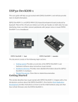
The Self-Balancing Robot control system consist two boards, Terasic DE10-Nano SoC FPGA board
and Motor Driver board (See Figure 2-1).
Figure 2-1 DE10-Nano and Motor Driver Board

Self-Balancing Robot
Hardware Manual
4
www.terasic.com
July 12, 2018
DE10-Nano board is responsible for the entire Self-Balancing Robot control system, user can use
the Nios system or ARM CPU to execute the robot balance algorithm and control other hardware on
the robot through SoC FPGA.
Motor Driver board is responsible for receiving motor control signal from DE10-Nano board, and
controlling the motor through the motor driver chip, besides, it receives control signal of Wi-Fi,
Bluetooth and IR protocol, then transmits the signal to DE10-Nano for further processing. The
motor driver board provides states data to DE10-Nano board via sensors, such as tilt angle of robot
body, battery voltage and distance information from ultrasonic module.
Figure 2-2 shows the block diagram of the robot that uses Nios to control the robot system. Figure
2-3 shows the block diagram of the robot which use ARM CPU to control the robot system.
Figure 2-2 Block diagram of the robot that uses Nios control system


Self-Balancing Robot
Hardware Manual
6
www.terasic.com
July 12, 2018
Chapter 3
DE10-Nano Board
This chapter will introduce the main devices of the DE10-Nano on the Self-Balancing Robot.
3
3.
.1
1
O
Ov
ve
er
rv
vi
ie
ew
w
Terasic DE10-Nano board presents a robust hardware design platform built around the Intel
Cyclone V SoC FPGA, beside to being used as traditional FPGA, it also combines the dual-core
Cortex-A9 processor and related controller. User can run Linux OS on DE10-Nano board, the board
provides powerful control and communication ability. Designed with small size and lower power
consumption, it is an excellent platform to develop portable applications. Figure 3-1 shows the
DE10-Nano board layout, Figure 3-2 shows the system block diagram of DE10-Nano. User can
refer to the following link for more detailed information about DE10-Nano board:
http://www.terasic.com.tw/cgi-bin/page/archive.pl?Language=English&CategoryNo=167&No=104
6&PartNo=4


Self-Balancing Robot
Hardware Manual
8
www.terasic.com
July 12, 2018
Before developing the robot application, users need to get familiar with FPGA develop tools and
process, master how to use DE10-Nano board, such as creating Quartus project, using Nios and
Qsys tools, mastering advanced skill (i.e. using ARM CPU in the SoC FPGA). Below sections
describe the considerations that needs to be paid attention to when using DE10-Nano on
Self-Balancing Robot and some commonly used interfaces on DE10-Nano.
3
3.
.2
2
T
Th
he
e
D
DE
E1
10
0-
-N
Na
an
no
o
f
fo
or
r
S
Se
el
lf
f-
-B
Ba
al
la
an
nc
ci
in
ng
g
R
Ro
ob
bo
ot
t
The DE10-Nano board used on the robot has a few differences with the retail version of the
DE10-Nano on the Terasic website. As shown in Figure 3-3, the main difference is that the
2x20-pin GPIO connector (GPIO0) and the 2x 5 ADC(J15) connector are on the bottom of the
DE10-Nano board on the robot, i.e. compared to the retail version of DE10-Nano board, the GPIO0
and ADC connectors on the DE10-Nano of the robot are the opposite of 180 degrees, which is
convenient to connect to motor driver board, as shown in Figure 3-4.
Figure 3-3 Special connectors position on the DE10-Nano board of the robot

Self-Balancing Robot
Hardware Manual
9
www.terasic.com
July 12, 2018
Figure 3-4 Connect DE10-Nano board to motor driver board via GPIO connector
3
3.
.3
3
2
2x
x2
20
0
P
Pi
in
n
G
GP
PI
IO
O
C
Co
on
nn
ne
ec
ct
to
or
r
The DE10-Nano board has two 2x 20-pin GPIO connectors, GPIO 1 and GPIO 0. The GPIO 1
connector can be used as an extension function. User can use this connector to connect to other
devices or daughter cards of the GPIO interface, such as Terasic D8M (800M pixel camera module).
As described in last section, The GPIO 0 connector is used to connect motor driver board and
transmit motor control signal and other communication/status signal (see Figure 3-5). In Addition,
the motor driver board provides 5V power to DE10-Nano board through the GPIO 0 connector.

Self-Balancing Robot
Hardware Manual
10
www.terasic.com
July 12, 2018
Figure 3-5 Connection between DE10-Nano GPIO 0 and motor driver board
For more interface on the motor driver board, please refer to the chapter 4 for detailed.
3
3.
.4
4
A
AD
DC
C
C
Co
on
nn
ne
ec
ct
to
or
r
As described in Section 2.2, the ADC connector is soldered on the DE10-Nano board’s bottom side,
it can connect to motor driver board conveniently as shown in Figure 3-6.

Self-Balancing Robot
Hardware Manual
11
www.terasic.com
July 12, 2018
Figure 3-6 The ADC connector on DE10-Nano board
The ADC 2x 5 pin connector is connected to A/D converter(LTC2308), finally connected to FPGA.
The A/D converter has a 500ksps, 8-channel interface. The battery voltage information on the
Self-Balancing robot will be transmitted to FPGA via ADC Connector and motor driver board
sensor circuit. The SoC FPGA system can read the battery voltage information and show the value
on smartphone APP.
3
3.
.5
5
L
LE
ED
Ds
s
There are some LEDs on the DE10-Nano which can be used for status display or user defined
purpose (See Figure 3-7). Under the factory setting, these LEDs will indicate power status, moving
direction, operate mode and so on. Table 3-1 describes the LEDs function.

Self-Balancing Robot
Hardware Manual
12
www.terasic.com
July 12, 2018
Figure 3-7 Indicator LEDs on DE10-Nano board
Table 3-1 Indicator LEDs on DE10-Nano board
LED name
LED status
Description
3.3V
power LED
Light On
Illuminate when 3.3V power is active
CONF_D
Light On
DE10-Nano board Configuration done
LED7
Light On
Robot is keeping balance status
LED6~5
1--Light On
0--Light off
00--robot is in default mode (Bluetooth & IR control)
01--robot is in default mode and implements
obstacle avoidance function
10--robot implements object following function and
obstacle avoidance
LED4
Light On
Battery power supply voltage is lower than 10.5V
LED3
Light On
Robot is turning right
LED2
Light On
Robot is turning left
LED1
Light On
Robot is moving backward
LED0
Light On
Robot is moving forward
Note: When all the LED3~0 are light on, the robot is in DEMO mode.
3
3.
.6
6
S
Sw
wi
it
tc
ch
he
es
s
The DE10-Nano board has four slide switches connected to the FPGA, which are allowed to be
used as data inputs for robot functions. In the factory setting, these switches are set to switch

Self-Balancing Robot
Hardware Manual
13
www.terasic.com
July 12, 2018
functions, such as enabling ultrasonic object following and obstacle avoidance, switching to
Bluetooth or IR remote control mode. Figure 3-8 shows the SW0 and SW1 on DE10-Nano board,
Table 3-2 describes the corresponding modes and functions when SW0 and SW1 are set to different
positions.
Figure 3-8 SW0 and SW1 on DE10-Nano board
Table 3-2 SW0 and SW1 purpose
SW[1:0]
Setting
Robot mode and
function
Description
00
Default mode
(Bluetooth &IR mode)
The robot can be controlled by
smartphone APP and IR remote control
10
Default mode &
Obstacle Avoidance
The robot can be controlled by
smartphone APP and IR remote
control, it implements the obstacle
avoidance function (Only IR remote
control supports)
01
Object following &
Obstacle Avoidance
The robot implements the object
following and obstacle avoidance (In
this mode, the robot will not be controlled
by smartphone APP and IR remote control)
11
Debug mode
Only support ARM version robot, the
control program will stop running, user
need to reboot the robot or run the
program again to control the robot.
Normally it is use to debug the robot.

Self-Balancing Robot
Hardware Manual
14
www.terasic.com
July 12, 2018
Note: 0-Switch is on Down position;1-Switch is on Up position
3
3.
.7
7
U
US
SB
B
B
Bl
la
as
st
te
er
r
I
II
I
C
Co
on
nn
ne
ec
ct
to
or
r
User can configure DE10-Nano SoC FPGA via USB Blaster II connector, use the Signaltab tool (In
the Quartus software) to debug, and program the EPCS128 device through JTAG chain. Figure 3-9
shows the USB Blaster II connector. Please refer to Getting_Started_Guide.pdf in the DE10-Nano
system CD on how to use the USB Blaster II connector.
Figure 3-9 USB Blaster II connector
3
3.
.8
8
2
2x
x2
20
0
E
EP
PC
CS
S6
64
4
D
De
ev
vi
ic
ce
e
The EPCS64 device is used to configure FPGA automatically when the DE10-Nano board is
powered on. As shown in Figure 3-10, please note the MSEL should be set to AS mode (MSEL[4:0]
= "10010") if FPGA is configured from EPCS64, user can use this MSEL setting to control the
self-balancing robot via Nios system.

Self-Balancing Robot
Hardware Manual
15
www.terasic.com
July 12, 2018
Figure 3-10 Set MSEL to AS mode
3
3.
.9
9
M
Mi
ic
cr
ro
o
S
SD
D
C
Ca
ar
rd
d
The board supports one Micro SD card socket on HPS side, it’s shown in Figure 3-11. User can
insert the Micro SD card with the pre-built Linux image into the socket and set the MSEL switch to
FPP x 32 mode: MSEL [4:0] = "01010", as shown in Figure 3-12. DE10-Nano board can boot up
from the SD card to run Linux OS. User can use this MSEL setting to control the self-balancing
robot via ARM system.
Figure 3-11 DE10-Nano micro SD card socket

Self-Balancing Robot
Hardware Manual
16
www.terasic.com
July 12, 2018
Figure 3-12 Set MESL to FPP x 32 mode
3
3.
.1
10
0
U
UA
AR
RT
T
t
to
o
U
US
SB
B
When running Linux OS on the DE10-Nano board, user can connect UART port with PC via
Mini-B USB cable and debug. User can refer to Getting_Started_Guide.pdf in the DE10-Nano
System CD on how to use the UART port.
Figure 3-13 UART to USB port
3
3.
.1
11
1
P
Po
ow
we
er
r
J
Ja
ac
ck
k
o
on
n
D
DE
E1
10
0-
-N
Na
an
no
o
The DE10-Nano board has a 5V power jack used as power input, as shown in Figure 3-14. The

Self-Balancing Robot
Hardware Manual
17
www.terasic.com
July 12, 2018
board can be powered through a DC 5V@2A power adapter when user wants to use the DE10-Nano
board separately.
Figure 3-14 5V DC power jack for DE10-Nano board
Caution! In the Self-Balancing robot's power system, the DE10-Nano's power supply is provided
by the motor driver board via GPIO 0. When using the robot, please do not connect any 5V power
supply to this Power JACK. Also, do not use a 12V lithium battery to connect this power jack (See
Figure 3-15 ).

Self-Balancing Robot
Hardware Manual
18
www.terasic.com
July 12, 2018
Figure 3-15 Connect Power JACK to 12V Battery is banned
3
3.
.1
12
2
O
Ot
th
he
er
r
I
In
nt
te
er
rf
fa
ac
ce
es
s
o
on
n
D
DE
E1
10
0-
-N
Na
an
no
o
B
Bo
oa
ar
rd
d
Regarding how to use other interfaces on DE10-Nano board, such as HDMI TX, Ethernet and USB
OTG, please refer to DE10-Nano_User_manual.pdf and datasheets in the DE10-Nano system CD.

Self-Balancing Robot
Hardware Manual
19
www.terasic.com
July 12, 2018
Chapter 4
Motor Driver Board
This chapter describes the functions and devices on motor driver board. The main function of this
board is receiving motor control signal from FPGA, control the motor through motor control circuit.
Besides, the board has communication components, such as Bluetooth and Wi-Fi module, IR remote
control, ultrasonic module. The board has analog sensors which can provide motion tracking and
battery voltage information.
4
4.
.1
1
B
Bo
oa
ar
rd
d
L
La
ay
yo
ou
ut
t
Figure 4-1 shows the layout of the motor driver board.
Figure 4-1 The board layout of motor driver board
/