Page is loading ...


Self-Balancing Robot
User Guide
I
www.terasic.com
July 12, 2018
CONTENTS
CHAPTER 1
USING THE SELF-BALANCING ROBOT
..................................................................................... 1
1.1 CONTROL THE MOTOR .............................................................................................................................................. 1
1.2 DETECT THE MOTOR SPEED AND DIRECTION............................................................................................................. 8
1.3 GET THE TILT ANGLE OF ROBOT .............................................................................................................................. 14
1.4 DETECT OBSTACLE DISTANCE................................................................................................................................. 21
1.5 BALANCED SYSTEM ................................................................................................................................................ 27
1.6 USE THE BLUETOOTH .............................................................................................................................................. 29
1.7 USING THE IR CONTROLLER ................................................................................................................................... 36

Self-Balancing Robot
User Guide
1
www.terasic.com
July 12, 2018
Chapter 1
Using the Self-Balancing Robot
1
1.
.1
1
C
Co
on
nt
tr
ro
ol
l
t
th
he
e
M
Mo
ot
to
or
r
To keep the robot in vertical balance status, user need to control the rotation of the motor and make
sure the accelerated rotation direction is reversed to the robot tilt direction. User need to learn how
to control the rotation direction and speed of the motor.
This section describes how to control the motor forward rotation or reverse, also describes how to
control the speed of the motor. As general FPGA IOs of DE10-Nano are unable to drive the motor,
an extra motor drive chip or circuit is needed to drive the motors, the motor drive chip used on the
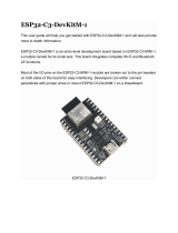
robot is Toshiba TB6612FNG, which can be used to control two DC motors simultaneously. As
shown in Figure 1- 1, the control signals--- IN1, IN2, PWM (control signals of motor A and B) and
STBY are connected to FPGA, the control signals --O1 and O2 output to the motor. The way to
control the rotation direction and speed of the motors is described as below.
Figure 1- 1 Block Diagram of Motor Driver Control Function
Note: As there are some photo couplers between the FPGA and TB6612FNG, the logic of control

Self-Balancing Robot
User Guide
2
www.terasic.com
July 12, 2018
signals output from FPGA should be opposite to the logic described in the TB6612FNG datasheet.
◼
◼
C
Co
on
nt
tr
ro
ol
l
R
Ro
ot
ta
at
ti
io
on
n
D
Di
ir
re
ec
ct
ti
io
on
n
Table 1- 1 lists the TB6612FNG control function.
Table 1- 1 TB6612FNG Control Function
⚫ Control the logic value for IN1 and IN2 can drive the motor to counterclockwise rotation (IN1
= 0; IN2 = 1) or clockwise rotation (IN1 = 1; IN2 = 0).
⚫ The motor will stop rotation when logics of both the two control signals (IN1 and IN2) are 0.
⚫ STBY is equal to Chip Enable function. The motor will stop and wait for new command when
STBY logic is 0.
In summary, user can easily change the motor rotation direction via controlling the IN1 and IN2
logic value.
◼
◼
C
Co
on
nt
tr
ro
ol
l
R
Ro
ot
ta
at
ti
io
on
n
S
Sp
pe
ee
ed
d
The motor speed of the motors can be controlled by controlling the Duty Cycle of the PWM signal.
FPGA Control Output
Driver Input
Driver
Output
Modes
description
MTRX_P
MTRX_N
MTR_PWMX
MTRX_STBY
IN1
IN2
PWM
STBY
O1
O2
--
0
0
1/0
0
1
1
1/0
1
0
0
Short brake
1
0
1
0
0
1
1
1
0
1
CCW
0
0
0
1
0
0
Short brake
0
1
1
0
1
0
1
1
1
0
CW
0
0
0
1
0
0
Short brake
1
1
1
0
0
0
1
1
OFF
(High
Impedance)
Stop
0/1
0/1
1/0
1
1/0
1/0
1/0
0
OFF
(High
Impedance)
Standby

Self-Balancing Robot
User Guide
3
www.terasic.com
July 12, 2018
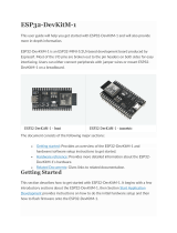
As shown in Figure 1- 2, the motor speed is faster while the PWM signal Duty Cycle is higher
(Which means the ratio of the high logic positive pulse duration to the total pulse period is higher).
Figure 1- 2 The diagram of different Duty Cycle
The maximum PWM frequency that TB6612FNG provides is 100KHz. For the Self-Balancing
Robot, the PWM frequency is set as 7.14KHz.
◼
◼
E
Ex
xa
am
mp
pl
le
e
D
De
es
sc
cr
ri
ip
pt
ti
io
on
n
Motor control IP TERASIC_DC_MOTOR_PWM.v is provided in the robot demo code. In this
demo, it is packed as Qsys component and used to control the right and left motor. User can find the
TERASIC_DC_MOTOR_PWM.v file in the robot system CD:
Demonstrations\BAL_CAR_Nios_Code\IP\TERASIC_DC_MOTOR_PWM
⚫
⚫
I
IP
P
S
Sy
ym
mb
bo
ol
l
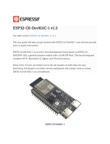
Figure 1- 3 shows the symbol of TERASIC_DC_MOTOR_PWM.v and its block diagram. The
main outputs are DC_MOTOR_IN1, DC_MOTOR_IN2 and PWM, others are Avalon interface
signals. The DC_MOTOR_IN1 and DC_MOTOR_IN2 are the control signals that can control the
motor rotation direction and stopping, which has been described in previous section. PWM control
signal is responsible for controlling the motor speed.

Self-Balancing Robot
User Guide
4
www.terasic.com
July 12, 2018
Figure 1- 3 TERASIC_DC_MOTOR_PWM.v symbol and block diagram
Table 1- 2 describes the Register Table of the motor control IP. Base Address 1~0 is the control
register of PWM, Base Address 2 is the control register of motor brake control. User can read these
registers value through Nios.
Table 1- 2 Register Table for TERASIC_DC_MOTOR_PWM.v IP
Reg Address
Bit
Field
Type
Name
Description
Base Addr +
0
31:0
R/W
total_dur
PWM total duration
value
Base Addr +
1
31:0
R/W
high_dur
PWM high duration
value
Base Addr +
2
31:3
-
Unused
Unused bit
2
R/W
motor_fast_decay
Motor brake control
1 for fast brake
0 for short brake
1
R/W
motor_forward
Motor direction control :
1 for forward
0 for backward

Self-Balancing Robot
User Guide
5
www.terasic.com
July 12, 2018
0
R/W
motor_go
Motor enable:
1 for start
0 for stop
⚫
⚫
I
IP
P
C
Co
od
de
e
D
De
es
sc
cr
ri
ip
pt
ti
io
on
n
a. Control Rotation Direction
Below is Partial code for controlling the rotation direction:
always @(*)
begin
if (motor_fast_decay)
begin
// fast decay
if (motor_go)
begin
if (motor_forward)
{DC_MOTOR_IN2, DC_MOTOR_IN1,PWM} <= {1'b1, 1'b0,PWM_OUT}; // forward
else
{DC_MOTOR_IN2, DC_MOTOR_IN1,PWM} <= {1'b0, 1'b1,PWM_OUT}; // reverse
end
else
{DC_MOTOR_IN2, DC_MOTOR_IN1,PWM} <= {1'b1, 1'b1,1'b0};
end
else
begin
// slow decay
if (motor_go)
begin
if (motor_forward)
{DC_MOTOR_IN2, DC_MOTOR_IN1,PWM} <= {1'b1, 1'b0,PWM_OUT}; // forward
else
{DC_MOTOR_IN2, DC_MOTOR_IN1,PWM} <= {1'b0, 1'b1,PWM_OUT}; // reverse
end
else

Self-Balancing Robot
User Guide
6
www.terasic.com
July 12, 2018
{DC_MOTOR_IN2, DC_MOTOR_IN1,PWM} <= {1'b0, 1'b0,1'b0};
end
end
The register values of motor control register are related to DC_MOTOR_IN1 and
DC_MOTOR_IN2 control signals, then user can control the motor rotation direction.
To drive the motors moving forward, user need set both motor_go and motor_forward as “1”. Then
the code “"DC_MOTOR_IN2, DC_MOTOR_IN1, PWM} <= {1'b1, 1'b0, PWM_OUT}; //
forward" will be executed.
DC_MOTOR_IN1 outputs logic 0 and DC_MOTOR_IN2 outputs logic 1. During the logic transmit
from FPGA to motor driver IC, they will be inverted to 1 and 0 respectively through the photo
coupler. IN1 and IN2 of TB6612FNG will receive logic 1 and 0 respectively. As shown in Table 4-1,
in this state, the motor will be clockwise rotation to drive the robot moving forward.
User can set motor_fast_decay as 1 and motor_go as 0 if they need a fast braking. Then, the below
code will be executed.
DC_MOTOR_IN2, DC_MOTOR_IN1, PWM} <= {1'b1, 1'b1,1'b0};
Finally, the IN1 and IN2 logic will receive logic 0 and logic 0 respectively. As shown in Table 4-1,
the motor is stopped.
The right and left motors on the robot are assembled opposite, so their rotation direction is opposite
too. As we use the same IP to control both the right and left motor, the control signals in project top
level file ( DE10_Nano_Bal.v) are defined opposite, as described in code below:
Qsys u0 (
//clock && reset
.clk_clk (FPGA_CLK2_50), // clk.clk)
.reset_reset_n (1'b1), // reset.reset_n
//right motor control
.dc_motor_right_conduit_end_1_pwm (MTR_PWMA), //
dc_motor_right_conduit_end_1.pwm
.dc_motor_right_conduit_end_1_motor_in1 (MTRR_P), // .motor_in1
.dc_motor_right_conduit_end_1_motor_in2 (MTRR_N), // .motor_in2

Self-Balancing Robot
User Guide
7
www.terasic.com
July 12, 2018
//left motor control
.dc_motor_left_conduit_end_1_pwm (MTR_PWMB), //
dc_motor_left_conduit_end_1.pwm
.dc_motor_left_conduit_end_1_motor_in1 (MTRL_N), // .motor_in1
.dc_motor_left_conduit_end_1_motor_in2 (MTRL_P),
b. Control Rotation Speed
Below is partial code for controlling the rotation speed:
////////////////////////////////////////
// PWM
reg PWM_OUT;
reg [31:0] total_dur;
reg [31:0] high_dur;
reg [31:0] tick;
always @ (posedge clk or negedge reset_n)
begin
if (~reset_n)
begin
tick <= 1;
end
else if (tick >= total_dur)
begin
tick <= 1;
end
else
tick <= tick + 1;
end
always @ (posedge clk)
begin
PWM_OUT <= (tick <= high_dur)?1'b1:1'b0;
end
The tick register is the main counter, total_dur represents the total_dur register described in Table
4-2. When the tick value equals to total_dur setting value, the whole counter will be reset and

Self-Balancing Robot
User Guide
8
www.terasic.com
July 12, 2018
recounted. PWM_OUT represents one PWM cycle is finished. So, the longer the PWM cycle is, the
larger the total_dur value will be. In this demo, the total_dur register is set to 7000 as default, it is
one PWM cycle when the counter counts to 7000. The output PWM frequency is 7.14KHz
(50MHz/7000).
As shown in Figure 1- 4, the motor speed depends on high_dur register. During one PWM cycle,
when the tick value is less than high_dur, the PWM output is 1; otherwise, the PWM output is 0. So,
the PWM Duty Cycle depends on the high_dur. Therefore, the larger the high_dur value is, the
Duty Cycle will be larger and rotation speed will be faster.
Figure 1- 4 The diagram of relationship between total_dur and high_dur in PWM
1
1.
.2
2
D
De
et
te
ec
ct
t
t
th
he
e
M
Mo
ot
to
or
r
s
sp
pe
ee
ed
d
a
an
nd
d
D
Di
ir
re
ec
ct
ti
io
on
n
Section 1.1 introduces how to control motor speed and direction, this section will introduce how to
use the Hall effect sensor and decoder on the motor to detect the motor speed and direction in real
time.
◼
◼
D
De
et
te
ec
ct
ti
io
on
n
P
Pr
ri
in
nc
ci
ip
pl
le
e
Figure 1- 5 shows the appearance of motor, there are two Hall effect sensors and one magnetic
Rotor on the motor. When the motor rotates, it will drive the magnetic Rotor to pass through the
Hall effect sensors, and then, the Hall effect sensor magnetic force will change and generate Hall
effect voltage, a digital circuit will process the Hall effect voltage and output square wave pulse
(See Figure 1- 6).

Self-Balancing Robot
User Guide
9
www.terasic.com
July 12, 2018
Figure 1- 5 the Hall effect sensor and magnetic Rotor on a motor
Figure 1- 6 Hall effect sensor and the square wave pulse
The two Hall effect sensors output two waves in different phases (Phase A and Phase B) as the two
sensor locations are different (See Figure 1- 7). When magnetic Rotor rotates, the first sensed
sensor will output wave first, and the other sensor output will delay. That is why the two waves
have different phases. So, we can know the motor rotation direction according which sensor wave
phase is ahead. Figure 1- 7 is the motor clockwise rotation status. In addition, we can also calculate
the motor speed according to the pulse number. Over a period of time, the faster the motor rotates,
the more pulses it generates.

Self-Balancing Robot
User Guide
10
www.terasic.com
July 12, 2018
Figure 1- 7 Hall effect decoder output A B Phase waves
Figure 1- 8 shows the motor phase pins connecting to FPGA. We can obtain the motor speed and
direction in real time by writing code to just detect the phase and pulse number of the two signals
(MTRR_IN_PA, MTRR_IN_PB).
Figure 1- 8 The motor phase pins connect to FPGA
◼
◼
E
Ex
xa
am
mp
pl
le
e
D
De
es
sc
cr
ri
ip
pt
ti
io
on
n
We do provide a Qsys IP in the Self-Balancing Robot demo for users to obtain the motor speed and
direction, the IP can be found in folder:
\Demonstrations\BAL_CAR_Nios_Code\IP\motor_measure\motor_measure.v
⚫
⚫
I
IP
P
S
Sy
ym
mb
bo
ol
l

Self-Balancing Robot
User Guide
11
www.terasic.com
July 12, 2018
Figure 1- 9 is the symbol and the system block diagram of motor_measure.v. Here we only draw
the detecting diagram of the motor on the right, and the motor on the left also has the same module
to detect the speed.
The module phase_AB[1:0] is used to connect the motor to receive the waves from the Hall effect
sensor. The module can detect and obtain the motor speed and direction and save the data in the
module register. CPU can read the data from Avalon bus.
Figure 1- 9 The motor_measure.v module and the system block diagram(for the motor on the right)
⚫
⚫
R
Re
eg
gi
is
st
te
er
r
T
Ta
ab
bl
le
e
Table 1- 3 is the IP register table. The Counter register in address “Base Addr+0” will counts the
motor pulse number. The system can detect how much the motor rotates according to this register,
and the positive number means clockwise direction, the negative number means counterclockwise
direction. Counter is read only register, the CPU can only read the Counter value. The Counter
register in address “Base Addr+2” is for write. The count_en register in address “Base Addr+1” is
for controlling the two Counters. When count_en is set to 1, the Counter register will start to count.
Table 1- 3 motor_measure.v IP Register
Reg Address
Bit Filed
Type
Name
Description
Base Addr + 0
31:16
RO
Unuse
-

Self-Balancing Robot
User Guide
12
www.terasic.com
July 12, 2018
15:0
RO
Counter (For
Read)
Read Counter
value for Motor
output pules
Base Addr + 1
31:30
RW
Unuse
-
1
RW
count_en
Enable Motor
pulse counter
Base Addr + 2
31:16
WO
Unused
-
15:0
WO
Couter (For
Write)
Set Counter
vaule
⚫
⚫
I
IP
P
C
Co
od
de
e
D
De
es
sc
cr
ri
ip
pt
ti
io
on
n
There is a submodule code TERAISC_AB_DECODER.v in motor_measure.v IP, this submodule
can detect phase A and phase B signals from the motor, and according the different phases, the
submodule can figure out whether the rotation direction is clockwise or counterclockwise. The
direction result will output to DO_DIRECT port and the rotation pulse will output to DO_PULSE
port. Then these two signal will pass to the motor_measure.v IP.
TERAISC_AB_DECODER u_decoder
(
.DI_SYSCLK(clk),
.DI_PHASE_A(phase_AB[0]),
.DI_PHASE_B(phase_AB[1]),
.DO_PULSE(conter_pulse),
.DO_DIRECT(direction)
);
Please refer to below code list in below, the motor_measure IP has a 16bit Counter (initial value is
16'h8000) register, which is enabled only if the "count_en" register is set to 1. In the beging When
the motor rotates clockwise (direction = 1), The Counter register will count from the initial value
and increase by the number of pulses returned from the motor; If the motor rotates
counterclockwise, the Counter register also will decrement with the number of pulses returned by
the motor. The system will periodically read the value of this Counter register to acquire the current

Self-Balancing Robot
User Guide
13
www.terasic.com
July 12, 2018
number of rotation speed of the motor.
always @( posedge clk)
begin
if(s_cs && s_write && s_address==`CNT_WRITE)
counter<=s_writedata[15:0];
else if(count_en && conter_pulse )
begin
if(direction)
begin
if(counter<16'hffff)
counter<=counter+1;
end
else if(!direction)
begin
if(counter>0)
counter<=counter-1;
end
else
counter<=0;
end
end
Users can refer to the Nios version demo file Motor.cpp (which location is
\Demonstrations\BAL_CAR_Nios_Code\software\DE10_Nano_bal) for the steps of system reading
counter. During the Self-Balancing Robot system initialization process, the count_en will be set to 1,
after this, the system will read the counter every 10ms. Every time after the reading, the system
will set the counter back to the initial value(16'h8000) and wait for the next reading time. The
system will use the latest counter value to minus the initial value (16'h8000), the result will be a
positive number if the motor direction is clockwise, the result will be a negative number if the
motor direction is counterclockwise.
The counter values of the two motors will finally transfer to the balancing PID algorithm.

Self-Balancing Robot
User Guide
14
www.terasic.com
July 12, 2018
1
1.
.3
3
G
Ge
et
t
t
th
he
e
t
ti
il
lt
t
a
an
ng
gl
le
e
o
of
f
R
Ro
ob
bo
ot
t
This section describes how to obtain the tilt angle of the Self-Balancing Robot, and how to get an
angularity correction to keep the robot balance.
◼
◼
H
Ho
ow
w
t
to
o
g
ge
et
t
t
th
he
e
t
ti
il
lt
t
a
an
ng
gl
le
e
o
of
f
t
th
he
e
b
bo
od
dy
y
The idealized state of the balance car is to maintain a vertical 90-degree angle to the ground.
However, there are only two wheels support the body, which is more likely to lean forward or
backward. It actually exists an angle of θ showing as Figure 1- 10. Our aim is to read out this angle
and feed it back to the balance system for controlling the motor rotating in the opposite direction. In
this way, it will make the tilt of the Angle to become the ideal 0 degree as a correction.
Figure 1- 10 The tilted angle of the balance car
To obtain the tilt angle of the body, the Motion Tracking device MPU-6500 on the robot will be
used. The single-chip MPU-6500 integrates a 3-axis accelerometer, and a 3-axis gyroscope. It is
able to read out the acceleration of there-axis (/g) from accelerator, and angular speed of three axes
(/Sec) from the gyroscope. The balance system will use both of these two sensors to compute the tilt
angle.
First of all, we need to obtain the status of the XYZ coordinates of the MPU-6500 in the robot.

Self-Balancing Robot
User Guide
15
www.terasic.com
July 12, 2018
From Figure 1- 11, It can be seen if the balance of the car is tilted forward or backward,
corresponding changes resulting the acceleration of the X-axis and Y-axis. Meanwhile, the angular
speed of the Y-axis will also change.
Figure 1- 11 Status of the XYZ coordinates on the mpu-6500
Continue to introduce how to calculate the tilt angle of the balance car from the accelerometer.
Figure 1- 12, ignore the horizontal acceleration of the car, there is a vertical angle θ when body tilts
forward or backward. G is for the acceleration of gravity. Resolve g vector into X and Z directions,
gx and gz are coordinate components for X-axis and Z-axis respectively, θ is the tangent angle of gx
or gz. Read out the values of gx & gz from the accelerometer in the MPU-6500. Get the degree of
angle θ by using the function θ = arctan(gx/gz).

Self-Balancing Robot
User Guide
16
www.terasic.com
July 12, 2018
Figure 1- 12 The tilted angle of the self-balance Robot
Besides, it can also get the body tilted angle from Y-axis angular rate by using the gyroscope in the
MPU-6500. See below Figure 1- 13, when the body tilts, the angular rate changes as well. Obtain
the angle in Y-axis via doing the integral calculation on the angular rate.

Self-Balancing Robot
User Guide
17
www.terasic.com
July 12, 2018
Figure 1- 13 The tilted angle of the self-balance Robot
There is an error in the angles calculated by the above two methods. When the accelerometer reads
the angle, the acquired value error will increase when the outside is disturbed. Use the gyroscope's
angular speed to integrate the acquired angle, due to the integral calculation will accumulate the
error, and increase with time, the error will become bigger and bigger. If you use the angle with
larger error to balance the system, it will be very difficult to stabilize the robot. Therefore, so a
method on Angle error correction is required.
It is common to use Kalman Filter as a method, which adopts the data fusion of two sensors (gyro
and accelerometer) to get a more precise angle.
Figure 1- 14 shows the comparison of the original tilt Angle (blue) and the Angle (orange) by
Kalman Filter. From the figure, you can see that the change in angle is large different for unfiltered
angle (blue). By working with these data, the balance of the car body could not be stable. However,
the varying amplitude for the orange Angle after filtering is significantly reduced.

Self-Balancing Robot
User Guide
18
www.terasic.com
July 12, 2018
Figure 1- 14 Comparison chart of the Kalman angle filter
◼
◼
M
MP
PU
U-
-6
65
50
00
0
O
Op
pe
er
ra
at
ti
io
on
n
FPGA uses I2C or SPI interface to control the MPU-6500, In our demo, we use the I2C interface to
read the register of the MPU-6500 with Salve Address 7'b1011001. The data registers of XYZ axis
accelerator and gyroscope locate in the range of 3B(Hex) ~ 48(Hex). It requires the initial operation
on starting up. For more details about the MPU-6500 and Register map, please refer to the
CD\Datasheet\Sensor\. And refer to the MPU.cpp & MPU.h provided in
CD\Demonstrations\BAL_CAR_Nios_Code\software\DE10_Nano_bal\ for control code.
◼
◼
E
Ex
xa
am
mp
pl
le
e
D
De
es
sc
cr
ri
ip
pt
ti
io
on
ns
s
We provide the Nios II demo for balance car by using the Open-core I2C module in Qsys. This
module allows Nios II to access the mpu-6500 through the I2C interface.
The function for obtaining the tilted angle is provided in path:
\Demonstrations\BAL_CAR_Nios_Code\software\DE10_Nano_bal\main.cpp, the main codes are
as following:
/**************************************************************************
/