Futureguard K110403637 Installation guide

Type
Installation guide
Mounting Bar Edge Rafters (2) Support Arms Small Screws
Top Trim Canopy Rafter Interlock Clips Large Screws
Front Gutter Slat Sections Deluxe Casting
Actual Size End Views of Door Canopy parts for easy reference and assembly:
mounting bar (a)
top trim (b)
support arms
(2) 36” - 84”
(3) 85” and over
slat sections
(4-10) based on
model ordered
deluxe casting
(1 per arm)
front gutter (c)
edge rafter (2) (d)
canopy rafter (e)
Phillips, Regular & 1/4” Hex Head
Screwdrivers or Bits Channel Lock Pliers Power Drill Level Tape Measure
Series 1100 Parts Check List:
Series 1100 with Support Arms
Required Tools:
slat section seams
Mounting Bar (A) Top Trim (B) Front Gutter (C) Edge Rafter (D) Canopy Rafter (E)
1
2
3
Series 1100
Aluminum Door Canopy
with Support Arms
It is our recommendation that you read instructions carefully
prior to assembly and installation.
QUANTITIES & SIZE OF PARTS MAY VARY BY AWNING SIZE AND MODEL SERIES
www.nuimageawnings.com
Assembly Instructions Series 1100 Aluminum Door Canopy with Support Arms
It is important that the Canopy Slats are assembled properly so that rain water
will not leak through the seams where the slats join.
The canopy is assembled upside down. Note that the Slat Sections are
packaged upside down (FIG. 1A). Assemble on a flat surface.
l
!
CAUTION: Canopy parts may have sharp edges. Use care in assembly.
Begin by laying the first slat out, curled edge DOWN on your left with ends
toward you. If your canopy is colored, place the colored side down. Slide each
subsequent slat into the curled UP edge on the right. Be sure the slats interlock
properly. (FIG. 1B)
When all slats are interlocked together, the Slat Section of the Canopy is ready
for the next step.
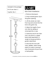
Slide the Top Trim onto Slat Section end with curl DOWN on the left and the
pre-punched holes of the Top Trim UP.
At the right end or end with the curl UP, slide the Front Gutter onto Slat Sec-
tion. Be sure to slide the Slat Sections correctly into the channel of the Front
Gutter as shown. Make sure the pre-punched holes of the Front Gutter are UP.
Slide the Top Trim out from Slat Section about 2 inches to provide clearance.
Next, slide the non-curved end of the Edge Rafter into Top Trim, making sure
the opposite, curved end of the Edge Rafter is up.
Next, slide both Top Trim and Edge Rafter back toward Slat Section and push
Edge Rafter onto slat section edge evenly until Slat Section and the Top Trim
are completely FLUSH into Edge Rafter.
Connect the Edge Rafter and Slat Section with the Front Gutter. Again, Slat
Section and Front Gutter MUST BE FLUSH in the Edge Rafter. With Slat Section
still secured flush in Edge Rafter, slide Front Gutter toward you and flush into
the Edge Rafter, aligning pre-punched holes. It will fit snug.
NOTE: Only the outside edge of the Front Gutter and the curled edge of the slat is
inserted into the Edge Rafter (FIG. 6).
Secure Edge Rafter in place. Secure Top Trim and Front Gutter with small screws
in the larger pre-punched holes at each end of the Edge Rafter.
Fasten small screws in the two larger pre-punched holes along Edge Rafter.
(Pairs of small holes are for the installation of optional Sidewings.)
NOTE: Support the underside of the Slats Section and apply pressure while
fastening screws. Repeat Edge Rafter assembly on the other side.
Slats have a slight
curve to them.
Keep them this
way for assembly.
Top Trim
Front
Gutter
Edge
Rafter
Front
Gutter
Curl
Up
Edge
Rafter
Curl
Down
NOTE: It is very important that both ends;
the top trim and the front gutter ends
along with the slat section are completely
flush in the edge rafter to be able to align
pre-punched holes for assembly.
Slight curve
Slat
TIP: Use the palm of your hand flat on
slats pulling toward you to help snug
them into Edge Rafter.
While keeping Slat Sections flush with each other, crimp slats together at
each seam interlock with a pair of channel lock pliers about 1/4 inch in from the
edge (not too much — only enough to secure them together). Be sure to keep
the plier teeth level with slats so that you do not accidentally bend them up
while crimping.
2
3
4
5
6
7
1
FIG. 2
FIG. 3
FIG. 4
FIG. 5
FIG. 6
FIG. 7
FIG. 1B
FIG. 1A
Align Canopy Rafter with pre-punched holes in the center of the Top Trim first
and secure with small screws. Then, repeat with the other end of the Canopy
Rafter in the center on the Front Gutter and secure with small screws.
NOTE: Door canopies wider than 60” need more than one canopy rafter.
Pre-punched holes will guide installation of multiple canopy rafters.
Connect Canopy Slat Section to the Canopy Rafter using Interlock Clips at each
joint where the slats interlock. Installing clips is a two-step process: (1) Insert
the curved part of clip into slat joint; (2) Slide clip onto Canopy Rafter. Interlock
Clips are installed on the flat section of the awning only, not at the curve. If
stubborn, make sure they are straight and parallel with the slat joint.
Install Mounting Bar and secure with large screws above the door. Support
Arms require a minimum of 3 inches above door. Be sure the Mounting Bar
is level and centered over the opening. Screws must be in studs or heavy
sheathing. (Drill alternate holes in bar if necessary.)
l
!
Caulk the top of the Mounting Bar against the house.
Attach Support Arms on Front Gutter with small screws. Install Deluxe Castings
to opposite ends of Support Arms and hand-tighten set screws. The Deluxe
Castings will need readjusting and leveling when fastening to the house.
For awnings 85” wide and over, attach a third arm in the center.
Canopy
Rafter
Interlock
Clip
Caulk
Mounting
Bar
3-inch
minimum
Deluxe
Castings
Arm
Front
Gutter
Adjust Support Arms for desired pitch. Be sure door opens completely before
attaching. Align Deluxe Castings, level and secure to wall with large screws.
Tighten set screws on brackets.
Installation of door canopy with Support Arms is now complete.
Deluxe
Castings
Top Trim
8
9
Installation Instructions
10
3
1
Support Arms
SERIES 1100
FIG. 8
FIG. 9
FIG. 1
FIG. 10
2
FIG. 3
small screw
lift
canopy
upward
insert
FIG. 2A
FIG. 2C
Lift the front of the canopy upward
and insert the Top Trim into the
Mounting Bar (FIG. 2A). Lower front
of canopy slowly and allow Support
Arms to rest on the house (FIG. 2B);
be sure the two parts are completely
interlocked. Align holes and secure
Top Trim to Mounting Bar with small
screws from bottom side (FIG. 2C).
interlocked
lower front
of canopy
slowly
support arm
deluxe
casting
FIG. 2B
www.nuimageawnings.com Customer Service 1-800-901-3313
Thank you for ordering the Series 1100 Aluminum Door Canopy
NuImage Awnings® has a full line of aluminum awnings to complement your selection. Contact your local
home improvement retailer, or visit www.nuimageawnings.com today to learn more about these other quality
products made in the USA.
Limited Warranty information
NuImage® Awnings and Canopies are manufactured by Futureguard® under the highest standards of production, after comprehensive research and development, and
will be warranted by Futureguard® to the original purchaser from date of purchase for a period of Five (5) years against the occurrence of manufacturing defects directly
resulting in peeling, flaking, blistering or rusting under conditions of normal use and service, subject to the terms and conditions contained in this Limited Warranty.
Futureguard® does not warrant installation nor defects caused by installation. This Limited Warranty does not cover any other defects as specified herein. This Limited
Warranty does not cover any other damage or material failure resulting from, but not limited to, normal weathering, oxidation, accidental damage or intentional
damage, fire or flood, windblown objects, windstorm, hail, sleet or chemical pollutants, mildew or structural defects, negligent maintenance or misuse or abuse, or any
other causes or occurrences beyond the control of Futureguard®.
Normal weathering may cause any surface to oxidize, chalk, gradually fade or accumulate surface dirt or stains due to varying exposures to sunlight, weather or
atmospheric conditions. The geographic location, the quality of the atmosphere and other local factors in the area, over which Futureguard® has no control, contribute
to the severity of these conditions.
This Limited Warranty is void if incompatible accessory products are installed which cause defects to occur.
The provisions of this Limited Warranty are the full and complete warranty policy extended by Futureguard®.
This Limited Warranty shall be null and void if harmful cleaning compounds are used.
THE WARRANTY STATEMENTS CONTAINED IN THIS LIMITED WARRANTY SET FORTH THE ONLY EXPRESS WARRANTIES EXTENDED BY FUTUREGUARD®, IN LIEU OF ALL
OTHER WARRANTIES, AND THE PROVISIONS OF THIS LIMITED WARRANTY SHALL CONSTITUTE THE ENTIRE LIABILITY OF FUTUREGUARD® AND THE PROPERTY OWNER’S
EXCLUSIVE REMEDY FOR BREACH OF THIS WARRANTY. FUTUREGUARD® SHALL NOT BE LIABLE TO THE PROPERTY OWNER FOR INCIDENTAL OR CONSEQUENTIAL
DAMAGES OF ANY KIND FOR BREACH OF ANY EXPRESS OR IMPLIED WARRANTY.
Some states do not allow the exclusion or limitation of incidental or consequential damages, so the above limitations or exclusions may not apply to you. This Warranty
gives you the specific legal rights and you may also have other rights, which vary from state to state.
Series 3100 Series 4100 Series 5500
Aluminum
Window Awning
with Support Arms
Aluminum Casement
Window Awning
with Support Arms
Aluminum Roll-up
Window Awning
Retractable Patio Awning
  • Page 1 1
  • Page 2 2
  • Page 3 3
  • Page 4 4

Futureguard K110403637 Installation guide

Type
Installation guide

Ask a question and I''ll find the answer in the document

Finding information in a document is now easier with AI