Optima Plus Installation & Operating
3
INSTALLATION OF TENSION RAFTER
Tools Required:
• Measuring Tape
• Electric Drill
• Drill Bits: #7 or 3/16"; 5/16"
• Center Punch
• Phillips Screwdriver
• Silicone Sealant
• ladder
• Pencil
• Wrench or Socket: 7/16"
• Pop Rivet Gun (Necessary only if backing plate is needed)
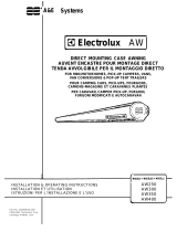
A. Install Black Adjustment Knob (see
FIG.1)
1. Attach the Tension rafter to the top bracket/pad
assembly with the 1/4-20 x 2-1/2" hex head bolt
and 1/4-20 lock nut with nylon insert provided.
(FIG 2A)
2. With awning closed, position the tension rafter at
the center of the awning so that it has a minimum
of 69" of unobstructed clearance below the aw-
ning rail. If windows and/or service accesses in-
terfere, relocate tension rafter as close to center
of awning as the situation will allow. (See FIG.
2B).
3. While holding tension rafter vertically at mounting
location, carefully set roller bracket end of tension
rafter on ground and loosen black adjustment
knob on side of tension rafter.
4. With tension rafter still resting on ground, extend
the tension rafter up so that the top of the tension
rafter almost touches the bottom of the closed
awning.
Black adjustment
Knob
Tension Rafter
FIG. 1
Awning Length
Equal
Equal
Awning
Optima Plus
Tension Rafter
Note: When installing two tension rafters
divide awning length into three equal parts.
1/4" X 2-1/2"
Hex Head Bolt
Pad
Tension Rafter
Top Bracket
1/4"-20 Lock Nut
with Nylon Insert
Top Cradle
FIG. 2A
FIG. 2B
Pad
Bottom
of Closed
Awning
Vehicle
90°
Right
Angle
Top
Bracket
Tension
Rafter
Important: For
tension rafter to
operate correctly,
bracket, cradle
and rafter must be
mounting at right
angles as shown.
90°
Right
Angle
5. Lock black adjustment knob on side of awning.
6. Carefully climb ladder. With tension rafter still
resting on the ground, position the top bracket/
pad assembly against the vehicle so that the top
cradle of the tension rafter touches the bottom of
the closed awning as shown in FIG. 3.
NOTE: It may be necessary to slightly extend the tension
rafter further to obtain the right angle shown in FIG. 3.
IMPORTANT: Tension rafter, top cradle, top bracket,
and vehicle MUST form right angles as shown in FIG.
3 for tension rafter to operate correctly.
7. Once right angles are established, mark location
of mounting holes in top bracket on vehicle.
8. Detach top bracket/pad assembly from tension
rafter by removing the 1/4-20 x 2-1/2" hex head
bolt and 1/4-20 lock nut.
FIG. 3