Page is loading ...

Wattstopper
®
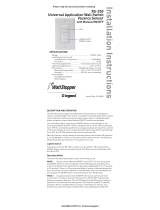
High Bay, Low Voltage, 0-10V Passive Infrared Occupancy Sensor
Détecteur de mouvement infrarouge passif, Basse tension 0–10V, Grande hauteur
Montaje alto, Bajo voltaje 0–10V, Sensor de ocupación infrarrojo pasivo
Installation Instructions • Instructions d’Installation • Instrucciones de Instalación
No: 27548 – 05/18 rev. 1
Catalog Numbers • Les Numéros de Catalogue • Los Números de Catálogo: HBP-202
Country of Origin: Made in China • Pays d’origine: Fabriqué en Chine • País de origen: Hecho en China
LENS COVERAGE
The HBP-202 occupancy sensor is modular, consisting of
two parts, a Sensor Module and a Lens. When used with the
HBP-L7 lens, the sensor is optimal for mounting heights of 20’
to 40’. There is an optional masking accessory for aisle way
applications. Snap it on and rotate to the desired position.
Lens and sensors are indoor rated and are ideal for warehouse
spaces. Avoid placing the sensor where shelving or other
obstructions may block the sensor’s line of sight.
Passive Infrared Sensing in Warehouses
Warehouses can have ambient temperature variations that may
affect sensor detection and coverage areas. High temperatures
at the covered area (above 80°F) reduce the detection zone
of the sensor. Consider adding more sensors if the ambient
temperatures are expected to be high. Additionally, high floor
level temperature may require larger movement for detection. In
some cases, sensors mounted above 40’ may only detect large
heat signatures such as forklift trucks. See the Best Practices
Guide for Warehouse at www.legrand.us for more information.
SPECIFICATIONS
Voltage .......................................................................... 12–32 VDC
Current Consumption ............................................. 10 mA maximum
Wiring .............................................................................22–18 AWG
Operating Temperature ..................... -40°F (-40°C) to 158°F (70°C)
Dimensions ..........3.52”L x 3.42”W x 2”H (89.5mm x 86.8mm 50.7mm)
Weight ............................................................................... 3.67 oz (104g)
Time Delay Adjustment .................................. 30 seconds – 30 minutes
DESCRIPTION AND OPERATION
The HBP-202 occupancy sensor is designed for automatic
lighting control in warehouse high bay applications with a 0–10V
output dimmable ballast or LED driver control.
The HBP-202 has a photocell to read the light level and can
continuously raise or lower the dimming level of the lighting
loads, based on the ambient light and the desired light level
setting.
The HBP-202 operates at 12–32 VDC. It is designed to be
installed in indoor and outdoor environments, and provides easy
to use selectable modes with several adjustable parameters.
The HBP-202 offers four different control modes of operation,
(plus service and test modes) that can be selected using a rotary
trimpot. Once powered up, each mode has a factory default set
of parameters. Additionally, sensor adjustment is available for
time delay and high/low dim levels via rotary trimpots.
NOTE: Length is 4.2” (106.6mm) before retaining clip is removed
and snap-in nipple is collapsed.
(50.7mm)
(86.8mm)
(89.5mm)
2”
3.52”
3.42”
Dimensions

2
HBP-L7: 360° Coverage
The HBP-L7 has a lens that covers a 100’ diameter area at a height of 40’.
50' 25' 0' 25' 50'
0'
50'
25'
25'
50'
100'
Coverage Top View @ 40’ Coverage Top View @ 40’ with Masking
50' 25' 0' 25' 50'
0'
50'
25'
25'
50'
100'
Standard Coverage Side View
Side View with Masking
0'
10' 10'
20' 20'30' 30'40' 40'
0'
27'
40'
50'50'
15'
0'
10' 10'
20' 20'30' 30'40' 40'
0'
27
'
40
'
50'50'
15'
Push HBP into fixture or junction box to snap into place.
Washers can be removed as needed to
accommodate thickness of fixture wall.
1
Remove retaining clip by pulling handle.
2
MOUNTING OPTIONS
The HBP series sensors feature a snap-in nipple design that provides quick, easy mounting, and secure attachment to a junction box or
fixture. The optional extender module (HBP-EM1) can be used to lower the sensor by up to 4 inches. The extender module provides several
mounting height options through the use of simple knock outs. Refer to the HBP-EM1 installation instructions for further details.
Push HBP into fixture or junction box to secure.
3
HBP secured to fixture or junction box
4

3
Nipple
Retaining Clip
Gasket
Extender
Module
Using the HBP-EM1 Extender Module
INSTALLATION
1. Determine the mounting location appropriate to the features of the
sensor and the coverage area. Careful consideration must be given
to sensor placement. Avoid placing the sensor where the edge of the
fixture, shelving or other obstructions may block the sensor’s line of
sight. Mount the sensor below the edge of the fixture and away from
the fluorescent lamps so that the heat from the lamps does not affect
the sensor.
2. Make sure that you have the appropriate accessories for the sensor
mounting configuration. (See Mounting Options.)
3. Assemble any necessary mounting accessories and attach them to
the sensor, making sure that the flying leads from the power module
are accessible.
4. Connect the line voltage and load wires to the sensor leads as shown
in the Wiring Diagram for the unit’s application.
• Do not allow bare wire to show.
• Make sure all connections are secure.
5. Restore power from the circuit breaker.
WARNING: TURN THE POWER OFF AT THE
CIRCUIT BREAKER BEFORE WIRING.
CONTROL MODES
Twist the lens counter clockwise to to remove the lens and access the rotary trimports that control the HBP-202
behavior. The HBP-202 has five selectable modes, each of which has preset parameter settings. Once the mode
is selected, you have the ability to further customize operation by adjusting the Set and the Time rotary trimpots.
Select the Mode and adjust the other rotary trimpots using a small screwdriver.
NOTE: A sixth mode, Test mode, is accessed automatically when mode A is selected. See page 5 for details.
Set – This rotary trimpot is used to adjust three different parameters, depending on the current mode: Desired Light
Level (in foot candles), Hold Off Setpoint, and High Trim.
• The HBP-202 has a photocell which measures the ambient light continuously. In Modes B, C, and D, this
trimpot will adjust the Desired Light Level, with a range from 0 footcandles to 200 footcandles, and the
HBP-202 will then adjust the dimming of the load so that the combined amount of
ambient light and electric light reaches the desired light level. When this trimpot is set to
the minimum position, the daylight control is disabled and the HBP-202 will adjust the
light level based only on occupancy without regard to ambient light.
• In Mode A, this trimpot determines the light level for the Hold Off Setpoint, with a
range from 0 footcandles to 200 footcandles. When set to the minimum position, the
light level hold off set-point is disabled.
• In Mode E, this trimpot controls the current dimming level, allowing visual confirmation
of the High Trim level. The high trim level is used to calculate the low dim amount,
which varies based on the mode, as described below. It also determines the maximum
lighting level in Mode A, and if the photocell is disabled, determines the maximum
lighting level for Modes B, C, and D.
Time – This rotary trimpot sets the amount of time delay after occupancy is no longer
detected before the loads go to the Low Trim value. Additionally, for Modes A and B, this
controls the amount of time before the load goes from the Low Trim to OFF. The time will
Dimming
Ballast/Driver
Neutral
120 – 277 VAC (1
φ
), 50/60 Hz
20A Ballast/ELV/MLV/Tungsten/LED
16A E-Ballast/CFL
1HP @ 120/240VAC
20A 120VAC Plug Load – Receptacle
Class 2 Output
24 VDC, 225 mA
BZ-200 Power Pack
UL 2043 Plenum Rated
www.wattstopper.com • 800.879.8585
16094r1
Appliance
Control
LISTED
88T9
Control
Common
+24VDC
Red
White
Neut.
Power Pack
Red
Black
Blue
Switch
Lighting
Load
Black
Any 3-Wire
24VDC
Sensor
Hot
Red
Ground
Green
Class 2
wiring only
Line
Ground
0-10V – (Gray)
0-10V + (Violet)
+VDC (Red)
CTRL (Blue)
COM (Black)
WIRING
10V
15M
S
e
t
1V
C
B
A
Mode
D
E
30S30M
Time
120 – 277 VAC (1
φ
), 50/60 Hz
20A Ballast/ELV/MLV/Tungsten/LED
16A E-Ballast/CFL
1HP @ 120/240VAC
20A 120VAC Plug Load – Receptacle
Class 2 Output
24 VDC, 225 mA
BZ-200 Power Pack
UL 2043 Plenum Rated
www.wattstopper.com • 800.879.8585
16094r1
Appliance
Control
LISTED
88T9
Control
Common
+24VDC
Red
White
Neut.
Power Pack
Red
Black
Blue
Switch
Lighting
Load
Black
Any 3-Wire
24VDC
Sensor
Hot
Red
Ground
Green
Class 2
wiring only
+VDC (Red)
CTRL (Blue)
Non-Dimming
Ballast/Driver
Neutral
Line
Ground
COM (Black)
(Gray)
(Violet)
Twist to remove lens
and expose trimpots

4
be half of the initial delay. For example, if time is set to 20 minutes, the load will go from ON to the Low Trim level 20 minutes after
occupancy is no longer detected. The the load will then turn OFF 10 minutes after it goes to the Low Trim level.
Fade Time – For all modes except Mode E and Test Mode, the fade up time from OFF to ON or OFF to High Dim Level is 2 seconds,
and the fade down time from ON to Low Dim Level or Low Dim Level to OFF is 10 seconds. For Mode E and Test Mode, fade up and
fade down time is 0 seconds.
Mode A – High/Low/Off Dimming for Indoor Parking Structure or High-Bay
Features: Transition between High, Low, and Off levels; Adjustable Hold Off Setpoint; High trim and low dim levels are
variable
This mode has a hold off light level set point, which can be adjusted to the desired light level
using Set trimpot, or disabled (when the Set trimpot is turned to the minimum setting).
Anytime occupancy is detected with ambient light level below the hold off set point, the load
turns ON (ramping up to the High trim level).
NOTE: In this mode, since there is no daylighting control, the High Trim level will be the
maximum amount of light for the load. (The High Trim level is set in Mode E.)
Once no occupancy is detected and the time delay expires, the load will fade down to the Low
Dim level which is 10% of High Trim level. As long as the area remains unoccupied, the load
stays at the Low Dim level for half the amount of the time delay, and then load turns OFF.
When the hold off light level set point is enabled using the Set trimpot, once the Load turns
OFF, after 5 seconds if the ambient light level is more than the set point value, the load will
stay OFF even if occupancy is detected. But if occupancy is detected within the 5 seconds,
the load will return to the High Trim value, even if the ambient light level is more than the hold
off level.
NOTE: When you select mode A, The HBP-202 will initially enter Test mode and stay in test mode for 5 minutes, after which it will switch
to mode A operation. (Test Mode is identical mode to A, with the exception of Time Delay, which is fixed at 5 seconds.)
Mode B – Continuous Dimming Control with Daylighting (Dim to Off )
Features: Adjustable photocell level to set desired light level when occupied
When the ambient lighting is below the desired light level and occupancy is
detected, the sensor turns the loads ON. The dimming level continually adjusts so
that the dimming amount combined with ambient light matches the desired light
level. If the ambient lighting is above the desired light level when occupancy is
detected, the load will remain OFF until the ambient light drops below the target
level, at which point it will adjust the dimming level appropriately.
Once no occupancy is detected and the time delay expires, the load fades down
to the Low Dim level, which is 50% of the High Trim level. As long as the area
remains unoccupied, the load stays at the Low Dim level for half the amount of the
time delay, and then load turns OFF. If the current dimming level is less than half of
the High Trim value, the load fades down to OFF without any time delay.
NOTE: With the photocell enabled in this mode (as well as in modes C and
D), the High Trim is used only to calculate the Low Dim amount. It
can therefore be set to an amount lower than the maximum dimming
amount, which is set based on the desired light level. For example: if
the High Trim level is set to 8V, in Mode B the Low Dim level will be 4V.
But if the desired light level is set high, the lights might go up to 9V or
10V in order to reach the desired level.
NOTE: If the photocell is disabled in this mode (as well as in modes C and D),
the High Trim amount will be used to determine the desired light level,
as it does in Mode A.
Mode C – Continuous Dimming Control with Daylighting (Dim to
Low Level)
Features: Adjustable photocell level to set desired light level; a minimum
light level is always maintained.
When occupancy is detected and if the ambient lighting is below the desired
light level, the dimming level continually adjusts so that the dimming amount
combined with ambient light matches the desired light level. If the ambient
lighting is above the target photocell level, the dimming level will adjust to the
Low Dim level (20% of High Trim value).
Once the area is unoccupied and the time delay expires, the load level will fade
down to the Low Dim level (20% of High Trim value). The load will never turn
completely OFF.
0
Desired
Light
Level
Night NightDay
Low
Dim*
Occupancy
Time Delay
Dimming when
using Photocell
Dimming with
Photocell disabled
*Low Dim = 20% of High Trim
0 – 10V Dimming Level
Mode C
Ambient and
Lighting Levels
Desired
Light
Level
Low
Dim*
Daylight
Lighting Loads
0
Desired
Light
Level
Night NightDay
Low
Dim*
Occupancy
Time Delay
1/2
Time
Delay
Dimming when
using Photocell
Dimming with
Photocell disabled
*Low Dim = 50% of High Trim
Mode B
Ambient and
Lighting Levels
Desired
Light
Level
Low
Dim*
Daylight
Lighting Loads
0 – 10V Dimming Level
Target Level
0
High
Trim
Day DayNight
Low
Dim
Occupancy
During Day time, load will not turn ON at
occupancy if ambient light above Hold Off setpoint
Time Delay
Mode A
1/2
Time
Delay
0 – 10V Dimming Level

5
Mode D – Continuous Dimming Control with Daylighting (Separate Low Dim Levels when there is No Occupancy)
Features: Adjustable photocell level to set desired light level; a minimum light level is always maintained, with separate day time
and night time minimum levels
During the day time, when occupancy is detected and if the ambient lighting
is below the desired light level, the dimming level continually adjusts so that
the dimming amount combined with ambient light matches the desired light
level. Once the dimming level reaches 40% of the high trim level, the sensor
will consider it to be night time and will behave as described in the following
paragraph. If the ambient lighting is above the target photocell level, the
dimming level will adjust to the Day Time Low Dim level (20% of High Trim value).
Additionally, when there is no occupancy and the time delay expires, the load level
will fade down to the Day Time Low Dim level.
During the night time, when occupancy is detected, the dimming level adjusts to
the desired light level. When there is no occupancy and the time delay expires, the
load level will fade down to the Night Time Low Dim level (40% of High Trim value)
in order to maintain a safe light level. Once the dimming level is less than 40% of
the high trim operation, the sensor switches back to day time operation.
In this mode, the load will never turn completely OFF.
NOTE: If the photocell is disabled, then the day time/night time behavior does
not apply. In this case, after the time delay expires the lights will dim to
40% of the High Trim level, and then after an additional 1/2 of the time
delay amount, the lights will dim further to 20% of high dim level.
Mode E – Service/Setup Mode
Features: Allows visual adjustment of High Trim level
If the Time trimpot is set at maximum, the load turns ON at the current High Trim amount.
Adjust the Set trimpot to the desired amount. This amount will be the maximum amount of light
in Mode A and will set the High Trim amount for Modes, B, C, and D. If the Time trimpot is set
at minimum, the load turns OFF.
Note that after turning the Time trimpot to change the ON/OFF setting, the unit will not respond
to further changes for 3 seconds.
Test Mode
Test mode sets the time delay to 5 seconds to allow for testing the occupancy sensor.
Whenever Mode A is selected using the Mode trimpot, the HBP-202 will enter Test mode for 5 minutes. If the HBP-202 is currently in
mode A, selecting another mode and then returning to mode A will restart Test mode. During Test mode, daylight control is not active
and the value of the Time trimpot is overridden. When occupancy is detected the load will turn ON at the High Trim value. Once no
occupancy is detected, the load will got to the Low Dim level after 5 seconds, and then will stay at that level for 2.5 seconds, before
turning OFF. After 5 minutes, the unit will revert to normal Mode A operation.
Mode Summary
Daylight Control High/Low Dim Time Delay Auto On Auto Off
Mode A No High Trim/
10% of High Trim
30sec – 30 min
1/2 of set value
during Low Trim
Occupancy detected One half time delay expired
Mode B* Yes High Trim/
50% of High Trim
30sec – 30 min
Default – 15 min
Occupancy detected One half time delay expired
or ambient light level above
target photocell level
Mode C Yes High Trim/
20% of High Trim
30sec – 30 min Occupancy detected Load is Always ON
Mode D Yes High Trim/
20% of High Trim in Day
40% of High Trim at Night
30sec – 30 min
1/2 of set value
during Low Trim
Load is always ON Load is Always ON
Mode E No High Trim Not applicable Load is ON at Dim level
when time delay rotary
trimpot in maximum
position
Load is OFF when time
delay rotary trimpot in
minimum position
* Default Mode Setting
0
Desired
Light
Level
Night NightDay
Low
Dim*
Occupancy
Time Delay
Dimming when
using Photocell
Dimming with
Photocell disable
d
*Low Dim = 40% of High Trim In Night Time, 20% in Day Time
If Photocell is disabled, initial Low Dim is 40%, then 20% after 1/2 time delay
Mode D
Ambient and
Lighting Levels
Desired
Light
Level
Low
Dim*
Daylight
Lighting Loads
Target Level
Night Low Dim Day Low Dim
0 – 10V Dimming Level
1/2
Time
Delay
0
10
High
Trim
Mode E
Applies Day or Night
Time Delay
set to maximum
Time Delay
set to minimum
3 seconds needed between changes
0 – 10V Dimming Level

6
TROUBLESHOOTING
Lights do not turn ON at Full Value:
• Make sure that the sensor is not obstructed.
• If Mode is set to A or B, check light level parameter, to find out the amount of light that the sensor is detecting. Cover the sensor
lens to simulate darkness in the room. If the lights come ON, the ambient light level is too high.
• While in Modes A or B, if the red LED blinks 2 times per second when the sensor is triggered, the ambient light level is too high.
• Make sure the HBP-202 is not set to Mode E (Service mode) and time delay rotary trimpot is not at minimum position.
• If lights still do not turn ON, call 800.879.8585 for technical support.
Lights will not go to Dimming Level:
• Check all wire connections and verify the dimming wires are tightly secured.
• Make sure that the sensor is not obstructed.
• Check desired light level setting, to find out the amount of light that the sensor is detecting. Cover the sensor lens to simulate
darkness in the room. If F, the ambient light level is too high.
• The time delay can be set from a minimum of 30 seconds to a maximum of 30 minutes. Ensure that the time delay is set to the
desired delay and that there is no movement within the sensor’s view for that time period.
• To quickly test the unit operation, enable test mode and move out of the sensor’s view. Lights should fade to the dim level after 5
seconds and then turn OFF after 2.5 seconds.
• If lights still do not turn adjust to the dimming level, call 800.879.8585 for technical support.
Lights will not turn OFF:
• Make sure the HBP-202 is not set to Mode E (Service mode) and time delay rotary trimpot is not at max position.
• To quickly test the unit operation, enable test mode and move out of the sensor’s view. Lights should fade to the dim level after 5
seconds and then turn OFF after 2.5 seconds.
• False Triggering may occur if the sensor is exposed to high ambient temperature conditions, so ensure the installed location has
good ambient temperature.
• If lights still do not turn OFF, call 800.879.8585 for technical support.
ORDERING INFORMATION
Model Description
HBP-202 Low Voltage 0–10V High/Low-Bay PIR Sensor
HBP-L7 High/Low-Bay Lens for HBP Series 8ft – 40ft Mounting
HBP-EM1 High/Low-Bay Extender Module for HBP Series
BZ-50 Power Pack: 120/277VAC, 50/60Hz, 20A ballast or incandescent
BZ-150 Power Pack: 120/277VAC, 50/60Hz, 20A ballast or incandescent, with Hold-On and Hold-Off capability
BZ-200 Power Pack: 120/277VAC, 50/60 Hz, 20A Ballast/ELV/MLV/Incandescent/LED, 16A, E-Ballast/CFL/Plug Load
BZ-250 Power Pack: 120/277VAC, 50/60 Hz, 20A, Ballast/ELV/MLV/Incandescent/LED, 16A E-Ballast/CFL/Plug Load, with
Hold-On/Hold-Off capability
BZ-250-347 Power Pack: 120/347VAC, 50/60 Hz, 16A Ballast/ELV/MLV/Incandescent/LED/ E-Ballast/CFL, 15A Plug Load, with
Hold-On/Hold-Off capability

800.879.8585
www.legrand.us/wattstopper
No. 27548 – 05/18 rev. 1
© Copyright 2018 Legrand All Rights Reserved.
© Copyright 2018 Tous droits réservés Legrand.
© Copyright 2018 Legrand Todos los derechos reservados.
Wattstopper warranties its products to be free
of defects in materials and workmanship for a
period of five (5) years. There are no obligations
or liabilities on the part of Wattstopper for
consequential damages arising out of, or in
connection with, the use or performance of this
product or other indirect damages with respect
to loss of property, revenue or profit, or cost of
removal, installation or reinstallation.
Wattstopper garantit que ses produits sont
exempts de défauts de matériaux et de fabrication
pour une période de cinq (5) ans. Wattstopper
ne peut être tenu responsable de tout dommage
consécutif causé par ou lié à l’utilisation ou
à la performance de ce produit ou tout autre
dommage indirect lié à la perte de propriété, de
revenus, ou de profits, ou aux coûts d’enlèvement,
d’installation ou de réinstallation.
Wattstopper garantiza que sus productos
están libres de defectos en materiales y mano
de obra por un período de cinco (5) años. No
existen obligaciones ni responsabilidades por
parte de Wattstopper por daños consecuentes
que se deriven o estén relacionados con el
uso o el rendimiento de este producto u otros
daños indirectos con respecto a la pérdida
de propiedad, renta o ganancias, o al costo
de extracción, instalación o reinstalación.
WARRANTY INFORMATION INFORMATIONS RELATIVES À LA GARANTIE INFORMACIÓN DE LA GARANTÍA
INFORMACIÓN PARA HACER PEDIDOS
N.º de catálogo Descripción
HBP-202 Montaje alto, Bajo voltaje 0–10V, Sensor de ocupación infrarrojo pasivo
HBP-L7 Lente de Montaje Alto/Bajo para montaje de 8 – 40 pies para serie HBP
HBP-EM1 Módulo de extensión de montaje Alto/Bajo para la serie HBP
BZ-50 Fuente de alimentación: 120/277VCA, 50/60Hz, 20A balasto o carga incandescente
BZ-150 Fuente de alimentación: 120/277VCA, 50/60Hz, 20A balastro o carga incandescente, con capacidad de Mantener
encendido/ Mantener apagado
BZ-200 Fuente de alimentación: 120/277VCA, 50/60 Hz, 20A Balasto/ELV/MLV/Incandescente/LED, 16A, Balasto
eléctrico/LFC/Carga del enchufe
BZ-250 Fuente de alimentación: 120/277VCA, 50/60 Hz, 20A, Balasto/ELV/MLV/Incandescente/LED, 16A Balasto
eléctrico/LFC/Carga del enchufe, con capacidad de Mantener encendido/Mantener apagado
BZ-250-347 Fuente de alimentación: 120/347VCA, 50/60 Hz, 16A Balasto/ELV/MLV/Incandescente/LED/ Balasto eléctrico/
LFC, 15A Carga del enchufe, con capacidad de Mantener encendido/Mantener apagado
/