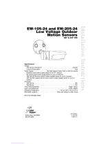
Installation Instructions
CX-105
PIR Occupancy Sensor
SPECIFICATIONS
Voltage .................................................................................... 24VDC
Current Consumption ............................................................... 8mA*
Power Supply ................................................................. Power Pack
......B series power packs supply powe for up to 14 CX-105 sensors
.......A series power packs supply power for up to 8 CX-105 sensors
Time Adjustment ........................................ 15 seconds—30 minutes
Sensitivity Adjustment .................................... Minimum—Maximum
*Current consumption can be slightly higher when only one sensor per power pack is
used.
Santa Clara, CA 95050

UNIT DESCRIPTION
The CX-105 is a 24VDC passive infrared (PIR) occupancy sensor which controls
lighting and HVAC systems based on occupancy.
PIR sensing systems are passive systems which react to changes in infrared energy
(moving body heat) within the coverage area. PIR sensors must directly “see”
motion of an occupant to detect them, so careful consideration must be given to
sensor placement.
COVERAGE PATTERNS
Coverages shown are maximum and represent coverage for walking motion. Actual
coverage will vary slightly depending on mounting height and furnishings.
Masking the lens: Opaque adhesive tape is supplied so that sections of the sensor’s
lens can be masked. This restricts the sensor’s view and allows you to eliminate
coverage in unwanted areas.
Call 800.879.8585 for Technical Support
Long Range Lens (-1)
10ft
0
8ft
8ft
16ft
16ft
0
10 15ft 55ft 85 90ft
TOP
SIDE
Long Range Lens (-1)
up to 90 linear ft for walking motion
0
3 ft
30ft
0
15ft
10 ft 10 ft 20 ft 30 ft 40 ft 50 ft0
33°using MB-1 with
maximum rotation
Narrow Aisle Lens (-4)
using MB-1 bracket
with maximum rotation
TOP
SIDE
One-Sided Aisleway Lens (-4)
up to 50 linear ft for walking motion
Aisleway Lens (-3)
pointed straight down
30ft
0
67ft 67ft38ft 38ft21ft 21ft10ft 10ft0
0
5ft
15ft
15ft
0
33.5ft 33.5ft
SIDE
TOP
Two-Sided Aisleway Lens (-3)
up to 134 linear ft for walking motion
Dense Wide Angle Lens (Standard)
SIDE
TOP
10ft
7ft15ft25ft 55ft0
50ft.
55ft.
Dense Wide Angle Lens (Standard)
up to 2000 sq ft for walking motion
up to 1000 sq ft for desktop motion

PARALLEL
to VERTICAL
at 10 foot
mounting
height
PARALLEL
to WALL
at 10 foot
mounting
height
Reference
Surface
Angle
Ceiling Mounted
Wall Mounted
Fig. B
INSTALLATION
The CX-105 sensors can be mounted
to walls or ceilings with the supplied
swivel bracket, and the supplied
junction box cover plate if necessary
(see figure C).
Mounting at fixture height is most
effective. The -3 & -4 sensors can
also be mounted to industrial fixtures
by using the MB-1 industrial mount
bracket.
Mounting
Ceiling: It is best to leave approximately six inches
between the sensor and the wall so that the Tightening
Screw can be easily accessed. Orient the Base Bracket’s Half-
Circle Notch in the direction that the sensor will point.
Wall: Orient the Base Bracket’s Half-Circle Notch, up.
Procedures:
1. Mount the Base Bracket to the mounting surface with screws.
2. At the center of the Base Bracket, drill a hole in the ceiling or wall (unless
mounting to a junction box) large enough to thread the sensor’s wires
through.
3. Guide the sensor’s wires into the Base Bracket and through the hole in the
ceiling or wall.
4. Connect the sensor to the Base Bracket by angling the Post Bracket so that it
is in line with the half circle notch, as illustrated in figure A. Push the ball into
the Base Bracket opening until it snaps into place, being careful not to pinch
the wires. The brackets can be easily connected or disconnected using this
orientation.
Half-Circle
Notch
Base
Bracket
Reference
Surface
Angle
Post
Bracket
Fig. A
Nut
Tightening
Screw
www.wattstopper.com

5. Insert the Tightening Screw and
Nut into the Base Bracket as
illustrated.
6. Use the Reference Surface Angle
to adjust the sensor for optimum
coverage. When mounted at ten
feet, the Reference Surface Angle
should be parallel to the wall or
the vertical (see figure B). (As the
mounting height decreases, the
sensor will be tilted up slightly; as
the mounting height increases, the
sensor will be tilted down slightly).
7. Tighten the Tightening Screw.
Industrial Mount Bracket MB-1
In an industrial setting, the MB-1 can be used
to mount the CX-105-3 or CX-105-4 to a
variety of structures or fixtures, including
fluorescent fixtures.
The MB-1 features an L-shaped
bracket and sensor housing. The
housing can be positioned so that the
sensor’s view is straight down
(CX-105-3), or directioned down
an aisle (CX-105-4).
When mounting the CX-105-4
with the MB-1 bracket
fully rotated, the coverage
pattern will extend slightly
behind the sensor’s mounting
position (see, Coverage
Patterns). The chart at right can
help to position the MB-1 for the
coverage desired.
Sensor Angle Adjustment
While watching the PIR sensing indicator (red LED) for flashes, have a person walk
back and forth at the far end of the space. Increase or decrease mounting angle as
needed until the desired coverage is achieved.
Tighten the Tightening Screw to hold this position.
CX-105-4
MB-1
Junction Box
with Mud-Ring
Mount to a
3” Mud-Ring
Junction Box
Cover Plate
(Mount to a
3” Mudring)
Ceiling
Swivel Bracket
Predrilled
Holes
Junction Box Cover Plate Installation
Fig. C
Call 800.879.8585 for Technical Support
Mounting
Height
Distance of
coverage behind
12” 2.5”
18” 4”
24” 5”
30” 6.5”

WIRING DIRECTIONS
CAUTION
Turn power off at the circuit breaker
before installing power packs or sensors.
Each WattStopper BZ series power pack can supply power for up to 14 CX-105
sensors.
When using more sensors than this, multiple power packs are required.
REFER TO THE WIRING DIAGRAMS ON THE NEXT PAGE FOR THE FOLLOWING
PROCEDURE:
Connect the low voltage:
• RED wire (+24VDC) from power pack to RED wire on sensor.
• BLACK wire from power pack to BLACK wire on sensor (Control Return) .
• BLUE wire from power pack to BLUE wire on sensor (Control Output 24VDC).
www.wattstopper.com

Control Output 24VDC
+24VDC
White (Neutral)
Red (Load)
Red (Line)
White
BlackHot
NPOWER PACK
Red
Black
Blue
Switch
Control Return
BLU
Wires
RED
BLK
Lighting
Load
CX-105
White (Neutral)
Red (Load)
Red (Line)
White
BlackHot
NPOWER PACK
Red
Black
Blue
Switch
Control Output 24VDC (BLU)
+24VDC (RED)
Lighting
Load
White (Neutral)
Red (Load)
Red (Line)
White
Black
Hot
N
POWER PACK
Red
Black
Blue
Switch
Control Return (BLK)
Control Output 24VDC (BLU)
+24VDC (RED)
Control Return (BLK)
Lighting
Load
CX-105
Occupancy
Controlled
Lighting
Multiple Sensors
and Lighting
Call 800.879.8585 for Technical Support

SENSOR ADJUSTMENT
The sensors are factory preset to allow for quick installation in most applications.
Ho
wever, verification of proper wiring or coverage, or customizing of the sensor’s
settings can be done through the following steps.
Before starting, make sure the office furniture is
installed, lighting circuits are turned on, and the
HVAC systems are in the overridden/on position.
VAV systems should be set t
o their highest airflow.
There is a warm-up period when power is first
applied to the sensor for one to two minutes.
1. For testing, set the Time Delay to
minimum, 15seconds. See chart below for
DIP switch configurations.
2. Ensure that the Sensitivity and Light
Level trimpots are set to maximum, fully
clockwise.
3. Remain still. The lights should turn off
after approximately 15 seconds (If not, see
Troubleshooting).
4. Set the desired Time Delay.
5. Readjust the angle of the sensor if necessary.
Time Delay:
The Time Delay is set with DIP Switches 1 thru 4.
Factory Default: 18 minutes.
LED
Sensitivity
Adjustment
Time-Delay
DIP Switch
on
25431
Time Delay
DIP Switch
on
25431
15 seconds
4 minutes
6 minutes
8 minutes
10 minutes
12 minutes
14 minutes
2 minutes
16 minutes
20 minutes
22 minutes
24 minutes
26 minutes
28 minutes
30 minutes
Override
18 minutes
12345
DIP Switch #
Time Delays
=factory preset
www.wattstopper.com

TROUBLESHOOTING
Lights do not turn on with occupancy, and the following condition exists:
LED does NOT flash:
When power is initially applied to the sensor, there is a warm-up period of up to
60 seconds before the LED is active.
1. Check that the circuit breaker has been turned back on.
2. Check the Sensitivity settings. Increase (clockwise) as needed.
3. Check all sensor and power pack wire connections.
4. Check for 24VDC at sensor (violet and green or gray wires).
• If 24VDC is present, replace the sensor.
• If 24VDC is not present, check that high voltage is present to power pack.
If it is, replace power pack.
LED does flash:
1. Check all sensor and power pack wire connections.
2. Check for 24VDC at the power pack’s blue wire connection to sensor while
someone moves in front of sensor to activate the LED. If there is no voltage,
replace the sensor. If there is voltage, replace the power pack.
Lights do not turn off automatically:
1. The sensor may be experiencing activations from outside the controlled area
or from some type of interference (see “Unwanted Sensor Activations” next
page).
2. Check all sensor and power pack wire connections.
3. Disconnect power pack’s blue wire:
• If the lights do not turn off, replace power pack. Reconnect blue wire.
• If the lights turn off, the problem may be in the sensor–to check:
4. Reconnect the blue wire.
5. Turn sensitivity and time delay to minimum and allow the sensor to time out.
• If the lights turn off, the sensor is working properly (see number 1., above,
and “Sensor Adjustment” for readjustment of sensor).
CAUTION
Turn power off at the circuit breaker
before working with or near high voltage.
Call 800.879.8585 for Technical Support

Unwanted Sensor Activations (LED flashes):
Possible causes
1. Improper sensor location or angle adjustment causing detection outside of
desired coverage area.
2. Sensitivity set too high.
3. Sensor located too close to HVAC or VAV vents with heavy air flow.
Possible solutions
1. Mask the lens to reduce PIR coverage (see “Masking the lens”, under
“Coverage Patterns”).
2. Reduce the sensitivity (counterclockwise) as needed (see “Sensor
Adjustment”).
3. Adjust the sensor angle (see “Sensor Adjustment”).
4. Relocate the sensor.
Override:
To override all sensor functions, set DIP switch #5 to on.
The red LED will come on and stay on for the duration of the override.
www.wattstopper.com

ORDERING INFORMATION
CX-105-3 Occupancy Sensor, Tw o-Sided Aisleway Lens
MB-1 Industrial Mount Bracket
CX-105
CX-105-1
Occupancy Sensor, Dense Wide Angle Lens (Std)
Occupancy Sensor, Long Range Lens
CX-105-4 Occupancy Sensor, One-Sided Aisleway Lens
BZ-50 Power Pack: 120/277VAC, 50/60Hz, 24VDC,
225mA w/relay connected, 20A ballast/20A incandescent
BZ-150 Power Pack, Hold ON/OFF, Manual ON: 120/277VAC,
50/60Hz, 24VDC, 225mA w/relay connected,
20A ballast/20A incandescent
All sensors are white.
WARRANTY INFORMATION
WattStopper warranties its products to be free of defects in materials and
workmanship for a period of five (5) years. There are no obligations or liabilities on
the part of WattStopper for consequential damages arising out of, or in connection
with, the use or performance of this product or other indirect damages with respect
to loss of property, revenue or profit, or cost of removal, installation or reinstallation.
70-0027-00r5 8/2014
Please
Recycle
2800 De La Cruz Boulevard, Santa Clara, CA 95050
800.879.8585 • www.wattstopper.com
/