Wincor Nixdorf TH320 User guide
- Category
- Print & Scan
- Type
- User guide

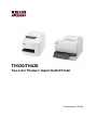
TH
320/TH420
Two-Color Thermal / Impact Hybrid Printer
Programmers Guide

We
would like to know
your opinion on this publication.
Please send us a copy of this page
if you have any constructive criticism on:
- the contents
- the layout
- the product
We would like to thank you in advance
for your comments.
With kind regards,
Wincor Nixdorf International GmbH
RD PD1
Rohrdamm 7
D-13629 Berlin
Your opinion:
TH320 / TH420, Programmers Guide, Edition December 2010

Co
pyright © Wincor Nixdorf International GmbH, 2010
The reproduction, transmission or use of this document or its contents is not permitted without express
authority. Offenders will be liable for damages. All rights, including rights created by patent grant or
registration of a utility model or design, are reserved.
Delivery subject to availability; technical modifications possible.

Cont
ents
Printer Status and Indicators 1
Startup diagnostics 1
Runtime Diagnostics 1
Remote Diagnostics 2
Indicators 3
Moving from the A756 to the TH320 4
Moving from the A756, A758 and TH420 to the TH320 (Slip Differences): 5
Commands 6
Emulation Commands 6
Set Printer ID Mode 6
Set Printer ID 6
Set Printer Emulation 6
TH320 Configuration Commands 7
Select Slip lines per inch 7
Select TH320 Narrow Slip Configuration Option to Ignore n Leading Spaces 7
Select TH320 Narrow slip 51 –column Compressed Print Option 7
Select TH320 Delete Slip Trailing Spaces Option 8
Select TH320 (21 and 25-line) Rotated Slip Print Options 8
Select TH320 Slip Stop Options 8
TH320 Configurable Slip Commands 9
Moving from A756/A758 to TH320 10
Two-color commands 10
Programming the Printer 12
Overview of Printing Characteristics 12
Character appearance 12
Receipt character specification 12
Print zones 13
Print zones for receipt station 80 mm paper 13
Print zones for slip station TH320 13
Print Zones for Slip, Validation TH320 14
Print zones for slip station TH420 15
Rotated printing commands 16
Command Descriptions 17
Command conventions 17
Printer actions 17
Clear printer 17
Close form 18
Open form 18
Perform partial knife cut 18
Return home 18
Select peripheral device (for multi-drop) 18
Initialize printer 19
Set slip paper eject length 19
Select receipt or slip for printing; slip for MICR read 19
Select receipt or slip for setting line spacing 20
Select paper sensors to output paper end signals 20
Select sensors to stop printing 20
Enable or disable panel button 21
Set slip paper waiting time 21
Generate pulse to open cash drawer 21
Release Paper 22
Set current color 22
Select slip station 22
Select receipt station 22
Select cut mode and cut paper 23

m Fe
ed and cut mode 23
Set paper type 23
Set interpretation of “Set current color” command 24
Print test form 24
Print and paper feed 25
Print and feed paper one line 25
Print and eject slip 25
Print and carriage return 25
Feed n print lines 25
Feed n dot rows 26
Print 26
Print and feed paper 26
Print and reverse feed paper 26
Print and feed n lines 27
Print and reverse feed n lines 27
Reverse feed n lines 27
Reverse feed n dots 27
Vertical and horizontal positioning 28
Horizontal tab 28
Add n extra dot rows 28
Set column 30
Set absolute starting position 30
Set vertical line spacing to1/6 inch 30
Set vertical line spacing 31
Set horizontal tab positions 31
Set relative print position 32
Select justification 33
Set left margin 33
Set horizontal and vertical minimum motion units 34
Set printing area width 35
Turn smoothing mode on/off 36
Text characteristics commands 36
Select double-wide characters 36
Select single-wide characters 36
Select 90 degree counter-clockwise rotated print 37
Select pitch (column width) 37
Set right-side character spacing 38
Select print mode 38
Select or cancel user-defined character set 39
Define user-defined character set 39
Select or cancel underline mode 40
Copy character set from ROM to RAM 41
Cancel user-defined character 41
Select or cancel emphasized mode 41
Select double-strike 42
Cancel double-strike 42
Select or cancel italic print 42
Select international character set 43
Select character code table 43
Selector cancel 90 degree clockwise rotated print 43
Selector cancel upside-down print mode 44
Select character size 44
Selector cancel white/black reverse print mode 45
Reverse color text mode 45
Text strike - through mode 46
Select super script or subscript modes 46
Graphics 46
Download BMP logo 46
Select bit image mode 47

Se
lect double-density graphics 48
Select the current logo (downloaded bit image) 49
Define downloaded bit image 49
Print downloaded bit image 50
Print raster monochrome graphics 51
Print raster color graphics 51
Print raster color graphics 51
Download logo image 52
Apply shading to logo 52
Merge watermark mode 53
Monochrome shade mode 53
Color shade mode 53
Logo print with color plane swap 54
Form and merge real-time surround graphic 54
Save graphics buffer as logo 55
Background logo print mode 55
Shade and store logo 55
Logo print with knife cut 56
Apply margin message mode 56
Set temporary max target speed 57
Set colorization 57
Set attribute mapping 60
Convert 6-dots/ mm bitmap to 8-dots/ mm bitmap 61
Enable constant speed logos 62
Allocate extra RAM for character build 62
Status Command 63
Transmit peripheral device status 63
Transmit paper sensor status 64
Transmit printer ID 64
Transmit printer ID, remote diagnostic extension 65
Transmit Status 68
Slip paper status (n = 3 or n = 51) 70
Real-time commands 71
Send Printer Software Version 72
Busy line and fault conditions 73
Real-time status transmission 73
Real-time request to printer 75
Real-time printer status transmission 76
Real-time commands disable 76
Unsolicited status mode 77
Select or cancel unsolicited status mode (USM) 77
Recognizing data from the printer 79
Barcodes 80
Select printing position of HRI characters 80
Select pitch of HRI characters 80
Select bar code height 80
Print barcode 81
Set GS1DataBar (RSS) parameters 83
Print GS1DataBar (RSS), data length specified 83
Print GS1DataBar (RSS barcode), null terminated 84
Select PDF 417 parameters 84
Select bar code width 85
Page mode 86
Print and return to standard mode 86
Cancel print data in page mode 86
Print data in page mode 86
Select page mode 87
Select standard mode 88
Select print direction in page mode 88

Se
t print area in page mode 89
Set absolute vertical print position in page mode 90
Set relative vertical print position in page mode 90
Macros 91
Select or cancel macro definition 91
Execute macro 92
MICR commands (TH320 MICR models only) 93
Read MICR data and transmit 93
Transmit last MICR read 93
MICR parsing 93
Define parsing format, save in NVRAM 93
Define parsing format, do not save permanently 94
Parsing parameter string options 94
Sample parsing formats 95
Check serial number 97
Loading the exception table 98
Exception table entry format 98
Maintaining the exception table 100
User data storage 100
Write to user data storage 100
Read from user data storage 100
Read from non-volatile memory 100
Write to non-volatile memory (NVRAM) 101
Select memory type (SRAM/flash) where to save logos or user-defined fonts 101
Flash memory user sectors allocation 101
Erase user flash sector 102
User storage status 103
Flash download 104
Switch to flash download mode 104
Return boot sector firmware part number 104
Return segment number status of flash memory 105
Select flash memory sector to download 105
Get firmware CRC 105
Return microprocessor CRC 105
Erase all flash contents except boot sector 106
Return main program flash CRC 106
Erase selected flash sector 106
Erase all flash contents except boot sector 106
Download to active flash sector 107
Download paper type description 107
Reset firmware 108
Return paper type description 108
Appendix 109
Commands listed by hexadecimal code 109
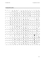
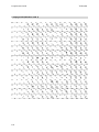
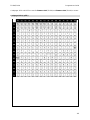
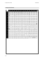
Character Sets 113
Character code 437: USA, Standard Europe 113
Codepage 737 (Greek) 114
Codepage 850 (Multilingual) 115
Codepage 852 (Slavic) 116
Codepage 857 (Turkish) 117
Codepage 858 (with Euro symbol) 118
Codepage 860 (Portuguese) 119
Codepage 862 (Hebrew) 120
Codepage 863 (French Canadian) 121
Codepage 865 (Nordic) 122
Codepage 866 (Cyrillic) 123
Codepage 1252 (Windows Latin 1) 124
Codepage 1251 (Cyrillic) 125
Codepage 1255 (Hebrew) 126

El
ectronic Journal 127
Electronic Journal Storage Commands 129
1F 0A C1 Enable Auto Journal Mode 129
1F 0A C2 Disable Auto Journal Mode 129
1F 0A C3 Clear Journal 129
1F 0A C4 Print Journal 129
1F 0A C5 Return Journal Status 129
1F 0A C6 Return Journal Flash Size 129
1F 0A C7 Write Journal RAM Data to Flash 130
1F 0A C8 Enable Direct Journal Mode 130
1F 0A C9 Disable Direct Journal Mode 130
1F 0A CA Electronic Journal NOP 130
1F 0A CB Electronic Journal Data scope 130
Print Journal Entry Mode 131
Print Journal Entry considerations in Auto Journal Mode 131
Print Journal Entry considerations in Direct Journal Mode 131
Entry Mode Commands 132
1F 0A D1 Enter Print Journal Entry Mode 132
1F 0A D2 Exit Print Journal Entry Mode 132
1F 0A D3 Move to End of Journal (most recent entry) 132
1F 0A D4 Move to Start of Journal (least recent entry or first line) 132
1F 0A D5 Move to next Journal entry (towards more recent entry) 132
1F 0A D6 Move to previous Journal entry (towards less recent entry) 132
1F 0A D7 n Move back n lines (towards less recent) 133
1F 0A D8 n Move forward n lines (towards more recent) 133
1F 0A D9 n Print n Lines 133
1F 0A DA Print Journal Entry (knife cut to knife cut) 133
1F 0A DB Enable Journal Cut 133
1F 0A DC Disable Journal Cut 133
TH420: Additional Features 134
Comparison to A756 135
Comparison to A756 135
Two-color commands (comparison A758 to TH420) 136
Colorization commands 137
Width Specifications 137
Emulation Modes 138
Status 139

TH
320/TH420 Programmers Guide
1
Printer Status and Indicators
The TH320/TH420 printers perform a number of diagnostics that provide useful information about the
operating status of the printers. The following diagnostic tests are available.
Startup diagnostics
Performed during the printer’s startup cycle.
Runtime diagnostics
Performed during normal printer operation.
Remote diagnostics
Maintained during normal operation and reported in the print test.
The printer can be configured with the following settings and functions through the configuration
menu that is printed on the receipt. For more information on configuring the printer, see TH320 and
TH420 User Guides “Printer configuration”.
Communication interfaces Diagnostic modes
RS-232c settings
Printer emulations/software options
Hardware options
Startup diagnostics
When the printer receives power or performs a hardware reset, it automatically performs the startup
diagnostics (also known as level 0 diagnostics) during the startup cycle. The following diagnostics are
performed:
Turn off motors and solenoids.
Perform boot CRC check of the firmware ROM, test external SRAM, test EEPROM, and test main
program CRC. Failure causes Startup Diagnostics to stop; the printer beeps and the light flashes a
set number of times, indicating the nature of the failure. The table in the “Indicators” section (page
16) describes the specific tone and light sequences.
Check if paper is present.
Return the knife to the home position.
Failure causes a fault condition. The table in the “Indicators” section (page 16) describes the specific
tone and light sequences.
Check if receipt cover is closed
Failure does not interrupt the startup cycle.
When the startup diagnostics are complete, the printer makes a two-tone beep (low then high
frequency), the paper feed button is enabled, and the printer is ready for normal operation.
If the printer has not been turned on before, or a new EEPROM has been installed, the default values
for the printer functions will be loaded into the EEPROM during startup diagnostics.
Runtime Diagnostics
Runtime diagnostics (sometimes called level 2 diagnostics) run during normal printer operation. When the
following conditions occur, the printer automatically turns off the appropriate motors and disables
printing to prevent damage to the printer:
Paper out
Receipt cover open
Knife unable to home
Print head too hot
Voltages out of range
The light on the operator panel will signal when these conditions occur as well as indicate what state or
mode the printer is in.

Pr
ogrammers Guide TH320/420
2
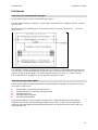
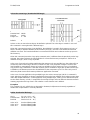
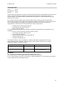
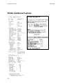
Remote Diagnostics
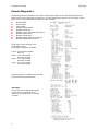
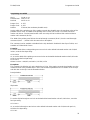
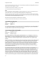
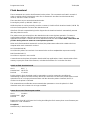
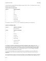
Remote diagnostics (sometimes called level 3 diagnostics) keeps track of the following tallies and
prints them on the receipt during the print test. See the sample test printout on the next page. These
tallies can be used to determine the printer’s state of health.
Model number
Serial number
CRC number
Number of lines printed
Number of knife cuts
Number of hours the printer has been on
Number of flash cycles
Number of cutter jams
Number of times the cover is opened
Maximum temperature reached
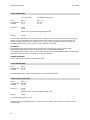
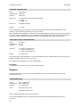
Paper type can be changed in the
configuration menu.
Paper types and grades available:
Type 0 - Monochrome grades
WN T 55
Type 1 - Two-color grades
Kanzaki P-310 RB
Type 4 - Two-color grades
Kanzaki P-310 BB
Type 5 - Two-color grades
Kanzaki P-320 RB
When the printer is configured for USB this
location will show the driver type.
Im
portant
:
En
sure that the configuration settings
match your host computer, if not,
enter the configuration menu to make
changes.

TH
320/TH420 Programmers Guide
3
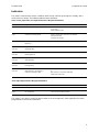
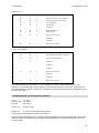
Indicators
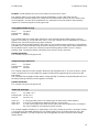
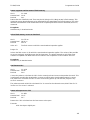
The printer communicates various conditions both visually, with two green lights or audibly, with a
series of tones or beeps. The following table lists these indicators.
Green on-line, paper status, error light (to there are of the paper feed button)
Indicator Sequence Condition
Li
ght Continuous, flashing quickly Paper out
Cover open
Knife unable to home
Li
ght Continuous, flashing slowly Paper is low (if paper low sensor is installed)
Print head too hot
Voltages out of range
To
ne Two-tone beep (low frequency, high
frequency)
Start up diagnostics completed successfully
Li
ght Single beep
and Tone Single light flash
Boot CRC test failure
Li
ght Double beep
and Tone Double light flash
SRAM test failure
Li
ght Triple beep
and Tone Triple light flash
EEPROM test failure
Li
ght Four beeps
and Tone Four light flash
Dynamic memory initialization failure
Li
ght Two-Tone beep
and Tone (high frequency, low frequency)
Continuous flashing of light
Main program CRC test failure
or
DIP switch is in on position indicating
Flash down load mode
Gr
een slip-in light (in front of the paper feed button)
In
dicator Sequence Condition
Li
ght Off No check or form inserted or are incorrectly inserted
Li
ght On (continuous) Check or form properly inserted
Th
e printer is also able to communicate its status to the host application if the application has been
programmed to receive this information.

Pr
ogrammers Guide TH320/420
4
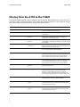
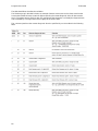
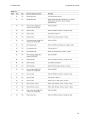
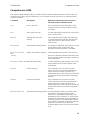
Moving from the A756 to the TH320
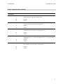
The following table details the list of commands whose behavior differs between the A756 printer and
the A758, TH420, and TH320 printers. This is due to the physical differences of the 6 dots/mm head in
the A756 and the 8 dots/mm head in the A758, TH420 and TH320.
Command Description Difference between theA756 and the TH320.
15 n Fe
ed n dot rows This command will move the paper on the receipt in n/203
inch steps instead of n/152 inch steps.
16 n Ad
d n extra dot rows The dot rows will be measured in n/203 inches versus
n/152 inches.
1B 2
0 n Set right-side character
spacing
This command sets the right side spacing to “n” horizontal
motion units. By default, these units are in terms of
1/203 inches versus 1/152 inches.
1B 2
4 n 1n2 Set absolute starting
position
For graphics commands, the position is scaled to best
ma
tch A756. In text mode, the equivalent character position
is
calculated.
1B 2
6 s c1 c2 n1 d1...nn dn] Define user-defined
character set
Since the dots on the TH320 print head are smaller, user
defined characters that were used on the A756 printers will
appear smaller on the TH320 printer.
1B 2
A mn 1n2d 1...dn Select bit image mode
In
A756 emulation mode, graphics are scaled to best match
th
e size of the graphic in the A756 printer.
1B 3
3 n Set line spacing This command uses n in terms of n/360 inches. Since the
A756 had a fundamental step of 1/152 inch and the TH320
has
a fundamental step of 1/203 inch, the actual line
spacing will not exactly match there quested spacing.
1B 4
An Print and feed paper This command uses n in terms of n/360 inches. Since the
A756 had a fundamental step of 1/152 inch and the TH320
has
a fundamental step of 1/203 inch, the actual line
spacing will not exactly match there quested spacing.
1B 5
9 n1 n2 d1...dn Select double-density
graphics
In A756 emulation mode, the printer scales the graphics to
provide the best match.
1B 5
C n 1 n2 Set relative print position The parameter to this command is in units of dots. How
ever, the command moves and aligns to character
positions. In A756 emulation mode, this command
shows many character positions to move based on the
A756 character width in dots (10) versus the TH320 (13).
1B 6
1 n Select justification This command does true dot resolution alignment for
centering versus character- aligned centering.
1D 2
An 1n2d 1...dn] Define down loaded bit
image
In A756 emulation mode, this command scales the
incoming data to provide a best match to the size of the
image as it printed on A756.
1D2
Fm Print down loaded bit
image
In A756 emulation mode, this command scales the
incoming data to provide a best match to the size of the
image as it printed on A756.

TH
320/TH420 Programmers Guide
5
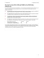
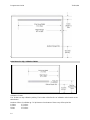
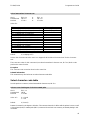
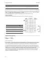
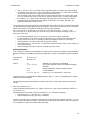
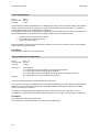
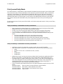
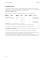
Moving from the A756, A758 and TH420 to the TH320 (Slip
Differences):
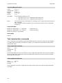
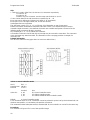
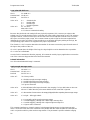
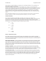
The impact station print zone on the TH420 is 4. 7 inches wide and the print zone on the TH320 is 3.0
inches. To compensate for the narrower print zone on the TH320 the firmware will provide the
following functionality:
For applications that currently use narrow forms using 42 or fewer columns, an option is provided to
delete x leading spaces. No application or form changes should be required.
For applications that use narrow forms using 51 or fewer columns, an option is provided to default to
compressed mode. No application or form changes should be required.
For applications using wide forms that print on less than 51 columns, options 1 and 2 above are
combined with the option to delete trailing spaces. There should be no changes required to the
application but a new form will be required.
For applications using wide forms that print on more than 51 columns, the data will wrap to the next
line. Modification of the application and the form is required if data wrapping is not desired.
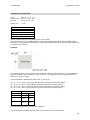
Impact Station Print Zone 4.7inches 3inches
Characters/row–Normal Mode 66 42
Characters/row–Compressed Mode 80 51
See Chapter “Programming the Printer” form or details about the slip print zones. Some commands
have new functionality for the slip and can be configured to been able or disabled on the slip. Existing
applications that use these functions on the receipt but not n the slip may need to be disabled
manually for the slip. The default is disabled for the slip.

Pr
ogrammers Guide TH320/420
6
Commands
Emulation Commands
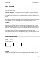
Se
t Printer ID Mode
Code (Hexadecimal) 1F 03 0C n
This command is ignored
Se
t Printer ID
Code (Hexadecimal) 1F 03 25 0F n
This command sets the printer ID response to the Printer ID command (1D4901)
n Printer ID
00 TH320
01 TH420
02 A758
03 A756
Se
t Printer Emulation
Code (Hexadecimal) 1F 03 25 02 n
n Emulation
00 Native
01 A756 limited emulation (See list of comments earlier in this chapter)

TH
320/TH420 Programmers Guide
7
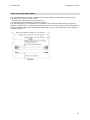
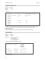
TH320 Configuration Commands
Se
lect Slip lines per inch
Code (Hexadecimal) 1F 03 25 04 n
This command sets the slip station lines per inch setting.
n Line spacing
00 7.2 LPI
01 6.0 LPI
Select Narrow Slip Configuration Option to Ignore n Leading Spaces Code (Hexadecimal)
Co
de (Hexadecimal) 1F 03 25 08 n
This command is available so TH420 applications can ignore n leading spaces in a 42 - column line of
text.
Range of n 0x00 < n < 0x20 hexadecimal
0<n<32 decimal
n=24 decimal is equivalent to printing the right most 42 columns of the TH420 print zone (24+42=66).
The first non-space in columns 1-n will stop ignoring leading spaces. Text over 42 columns will wrap to
the next line.
Tab (0x09), set column (0x1B0x14n), set absolute position (0x1B0x24NLNH), and set relative position
(0x1B 0x5CNLNH) commands are handled with in the range of ignored leading spaces.
Se
lect TH320 Narrow Slip Configuration Option to Ignore n Leading Spaces
Code (Hexadecimal) 1F 03 25 09 n
This command is available so TH420 applications can ignore n leading spaces in a 51-column line of
compressed text.
Range of n 0x00< n <0x20 hexadecimal
0<n<32 decimal
n=29 decimal is equivalent to printing the right most 51 compressed columns of the TH420 print zone
(29+51= 80).
The first non-space in columns 1-n will stop ignoring leading spaces.
Text over 51 columns will wrap to the next line.
Tab (0x09), set column (0x1B0x14n), set absolute position (0x1B0x24NLNH), and set relative position
(0x1B 0x5CNLNH) commands are handled with in the range of ignored leading spaces.
Se
lect TH320 Narrow slip 51 –column Compressed Print Option
Code (Hexadecimal) 1F 03 25 0A n
When enabled, all normal text is printed in 51 – column compressed print.
This accommodates existing applications printing up to 51 columns on the slip station.
The format will not match the A756/A758/TH420 exactly.
This will not affect rotated print mode (see below).
n 51 - column compressed print option
00 Disable (default)
01 Enable

Pr
ogrammers Guide TH320/420
8
Se
lect TH320 Delete Slip Trailing Spaces Option
Code (Hexadecimal) 1F 03 25 0B n
When enabled, all trailing spaces on the slip will be deleted.
This accommodates existing applications that send trailing spaces to the slip by not wrapping the
blank text to the next line.
The format will match the A756/A758/TH420 exactly, but a narrower form will be required.
This command will not work for an application that relies on wrapping text to print a line. A print
command is required.
n Delete slip trailing spaces option
00 Disable (default)
01 Enable
Se
lect TH320 (21 and 25-line) Rotated Slip Print Options
Code (Hexadecimal) 1F 03 25 0C n
21-line rotated text print accommodates existing applications, which print 21 or fewer rotated lines (as
read). The format will match the A756/A758/TH420 exactly.
25-line rotated text print accommodates existing applications, which print between 22 and 25 rotated
lines (as read). The format will not match the A756/A758/TH420 exactly.
An A756/A758/TH420 can print up to 33 rotated lines (as read), so those printing 26 or higher rotated
lines, cannot be emulated on theTH320 printer.
n Rotated Print Options
00 21-line (default)
01 25-line
Se
lect TH320 Slip Stop Options
Code (Hexadecimal) 1F 03 0D n
The TH420/A758/A756 mechanism has a positive slip stop for positioning a form at its top right corner.
Some applications rely on a form inserted to this slip stop to print on specific areas of the form. When
the top right corner of the form is at the slip stop, the first print line is 0.7" below the top of form. Some
applications rely on the operator manually positioning a form in order to print on specific areas of the
form.
When n = 01 the form is repositioned to 0.7 inches below the top of the form
The TH320 slip stop override option does not reposition an inserted form. (n = 00)
The TH320 slip stop distance option is triggered at the slip selection command (0x1B 0x63 0x30 0x04)
and positions an inserted form prior to print so that the first line of print will match a TH420/A758/A756.
n Slip Stop Option
00 No slip stop emulation
01 TH420 Slip Stop emulation (default)

TH
320/TH420 Programmers Guide
9
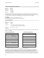
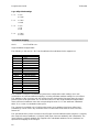
TH
320 Configurable Slip Commands
Code
Hexadecimal
Command
1F
032601 n Enables or disables the 1B 2110 command
n Do
uble high slip character print command (1B 21)
00 Disabled
01 Enabled
1F032602 n Enables or disables the 1B20 n command
n Sl
ip character right side spacing command (1B 20 n)
00 Disabled
01 Enabled
1F032603 n Enables or disables the 1D50 x y command
n Se
t minimum units for the slip station command(1D 50 x y)
00 Disabled
01 Enabled
1F032604 n Enables or disables the 1D4 C n L n Hand 1D57 n L n H commands
n Se
t left margin (1D 4C n L n H) and print width (1D 57 n L n H) on the slip station
commands
00 Disabled
01 Enabled
1F032605 n Enables or disables the 1B61 n command
n Pr
int justification on the slip station command (1B 61 n)
00 Disabled
01 Enabled

Pr
ogrammers Guide TH320/420
10
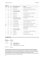
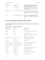
Moving from A756/A758 to TH320
Two-color commands
The following table details the list of commands related to two-color printing and functionality that was
not available on the A756 or the A758.
Hexadecimal ASCII Description
1B 7
2 m ESC r m Set current color
1D A0
n 1DGS Set temporary maximum target speed
1D 2
3n GS # n Select current logo
1D 4
2n GS B n Select or cancel white/black reverse print mode
1D 2
An1n2d1–dm GS * n1 n2 d1 – dm Define downloaded bit image
1D 2
Fm GS / m Print downloaded bit image
1D 8
1mn GS 0x81 m n Set paper type
1D 8
2 n 1–n72/n80 GS 0x82n 1–n72/n80 Print raster monochrome graphics
1D 8
3n1–n144/n160 GS 0x83n1–n144/n160 Print raster color graphics
1D 8
4 nmn1n2d1dx GS 0x84 n m n1 n2 d1 dx Download logo image
1D 8
5mn GS 0x85 m n Reverse color text mode (two-color)
1D 8
6m GS 0x86 m Monochrome shade mode
1D 8
7m GS 0x87 m Color shade mode
1D 8
9nm GS 0x89 n m Logo print with color plane swap
1D 8
B n m o GS 0x8B n m o Apply shading to logo
1D 8
C nm GS 0x8C n m Merge water mark mode
1D 8
Dnm GS 0x8D n m Text strike through mode
1D 8
E mn Ln Hd 1...dn GS 0x8E m nL nH d 1...dn Download paper type description
1D 8
Fm GS 0x8F m Return paper type description
1D 9
0 m x y o p q GS 0x8A m x y o p q Form and print real time surround graphic
1D 9
1n GS 0x91 n Save graphics buffer as logo
1D 9
2n GS 0x92 n Back ground logo print mode
1D 9
7mn GS 0x87 m n
User storage status

TH
320/TH420 Programmers Guide
11
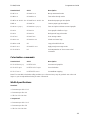
Hexadecimal ASCII Description
1D 9
7mn GS 0x87 m n
User storage status
1D 9
Anmo GS 0x9A n m o
Shade and store logo
1D 9
B mn
1DGS Logo print with knife cut
1D 9
9 l n m o GS 0x9B l n m o
Apply margin message mode
1F 0
3 16 05 n
US Set interpretation of “Set current color” command
1F 0
3 16 fm n o p q US ETX SYN Set Logo EZ
®
surround graphics
1F 0
3 16 f s p/r t US ETX SYN f s p/r t
Set colorization
1F 0
3 17 a m s US ETX ETB a m s
Set attribute mapping

Pr
ogrammers Guide TH320/420
12
Programming the Printer
Overview of Printing Characteristics
Commands control all operations and functions of the printer. This includes selecting the size and
placement of characters and graphics on the receipt or the slip and feeding and cutting the paper. The
programming commands have been organized, in order of hexadecimal code within functional groups.
For this reason, “related” commands may not be listed adjacent to one another.
The TH320 (TH320) standard command set allows it to work with software written for WN or other POS
compliant printers.
Any of the commands may be used in any combination to program a host computer to communicate with
the printer (unless otherwise noted).
For the printer to operate properly within an Ethernet environment, a specific set of commands must
be set.
Some commands listed and described here may not be implemented and are identified as “not
implemented.” If received, they are ignored and not sent to the print buffer as data.
Any non-legal commands have their parameter sent to the print buffer as data.
Character appearance
The appearance of text can be changed using the following print modes:
Standard
Underlined
Compressed
Bold
Double-high
Reverse
Double-wide
Italic
Upside-down
Strike-through
Rotated
Scaled
Shading
Receipt character specification
Standard
Characters per inch: 15.6
Characters per line: 44
Cell size: 13 × 24 dots
Compressed
Characters per inch: 20.3
Characters per line: 56
Cell Size: 10 × 24 dots
Page is loading ...
Page is loading ...
Page is loading ...
Page is loading ...
Page is loading ...
Page is loading ...
Page is loading ...
Page is loading ...
Page is loading ...
Page is loading ...
Page is loading ...
Page is loading ...
Page is loading ...
Page is loading ...
Page is loading ...
Page is loading ...
Page is loading ...
Page is loading ...
Page is loading ...
Page is loading ...
Page is loading ...
Page is loading ...
Page is loading ...
Page is loading ...
Page is loading ...
Page is loading ...
Page is loading ...
Page is loading ...
Page is loading ...
Page is loading ...
Page is loading ...
Page is loading ...
Page is loading ...
Page is loading ...
Page is loading ...
Page is loading ...
Page is loading ...
Page is loading ...
Page is loading ...
Page is loading ...
Page is loading ...
Page is loading ...
Page is loading ...
Page is loading ...
Page is loading ...
Page is loading ...
Page is loading ...
Page is loading ...
Page is loading ...
Page is loading ...
Page is loading ...
Page is loading ...
Page is loading ...
Page is loading ...
Page is loading ...
Page is loading ...
Page is loading ...
Page is loading ...
Page is loading ...
Page is loading ...
Page is loading ...
Page is loading ...
Page is loading ...
Page is loading ...
Page is loading ...
Page is loading ...
Page is loading ...
Page is loading ...
Page is loading ...
Page is loading ...
Page is loading ...
Page is loading ...
Page is loading ...
Page is loading ...
Page is loading ...
Page is loading ...
Page is loading ...
Page is loading ...
Page is loading ...
Page is loading ...
Page is loading ...
Page is loading ...
Page is loading ...
Page is loading ...
Page is loading ...
Page is loading ...
Page is loading ...
Page is loading ...
Page is loading ...
Page is loading ...
Page is loading ...
Page is loading ...
Page is loading ...
Page is loading ...
Page is loading ...
Page is loading ...
Page is loading ...
Page is loading ...
Page is loading ...
Page is loading ...
Page is loading ...
Page is loading ...
Page is loading ...
Page is loading ...
Page is loading ...
Page is loading ...
Page is loading ...
Page is loading ...
Page is loading ...
Page is loading ...
Page is loading ...
Page is loading ...
Page is loading ...
Page is loading ...
Page is loading ...
Page is loading ...
Page is loading ...
Page is loading ...
Page is loading ...
Page is loading ...
Page is loading ...
Page is loading ...
Page is loading ...
Page is loading ...
Page is loading ...
Page is loading ...
Page is loading ...
Page is loading ...
Page is loading ...
Page is loading ...
Page is loading ...
Page is loading ...
Page is loading ...
Page is loading ...
Page is loading ...
Page is loading ...
Page is loading ...
-
 1
1
-
 2
2
-
 3
3
-
 4
4
-
 5
5
-
 6
6
-
 7
7
-
 8
8
-
 9
9
-
 10
10
-
 11
11
-
 12
12
-
 13
13
-
 14
14
-
 15
15
-
 16
16
-
 17
17
-
 18
18
-
 19
19
-
 20
20
-
 21
21
-
 22
22
-
 23
23
-
 24
24
-
 25
25
-
 26
26
-
 27
27
-
 28
28
-
 29
29
-
 30
30
-
 31
31
-
 32
32
-
 33
33
-
 34
34
-
 35
35
-
 36
36
-
 37
37
-
 38
38
-
 39
39
-
 40
40
-
 41
41
-
 42
42
-
 43
43
-
 44
44
-
 45
45
-
 46
46
-
 47
47
-
 48
48
-
 49
49
-
 50
50
-
 51
51
-
 52
52
-
 53
53
-
 54
54
-
 55
55
-
 56
56
-
 57
57
-
 58
58
-
 59
59
-
 60
60
-
 61
61
-
 62
62
-
 63
63
-
 64
64
-
 65
65
-
 66
66
-
 67
67
-
 68
68
-
 69
69
-
 70
70
-
 71
71
-
 72
72
-
 73
73
-
 74
74
-
 75
75
-
 76
76
-
 77
77
-
 78
78
-
 79
79
-
 80
80
-
 81
81
-
 82
82
-
 83
83
-
 84
84
-
 85
85
-
 86
86
-
 87
87
-
 88
88
-
 89
89
-
 90
90
-
 91
91
-
 92
92
-
 93
93
-
 94
94
-
 95
95
-
 96
96
-
 97
97
-
 98
98
-
 99
99
-
 100
100
-
 101
101
-
 102
102
-
 103
103
-
 104
104
-
 105
105
-
 106
106
-
 107
107
-
 108
108
-
 109
109
-
 110
110
-
 111
111
-
 112
112
-
 113
113
-
 114
114
-
 115
115
-
 116
116
-
 117
117
-
 118
118
-
 119
119
-
 120
120
-
 121
121
-
 122
122
-
 123
123
-
 124
124
-
 125
125
-
 126
126
-
 127
127
-
 128
128
-
 129
129
-
 130
130
-
 131
131
-
 132
132
-
 133
133
-
 134
134
-
 135
135
-
 136
136
-
 137
137
-
 138
138
-
 139
139
-
 140
140
-
 141
141
-
 142
142
-
 143
143
-
 144
144
-
 145
145
-
 146
146
-
 147
147
-
 148
148
-
 149
149
-
 150
150
-
 151
151
-
 152
152
-
 153
153
-
 154
154
-
 155
155
-
 156
156
-
 157
157


Wincor Nixdorf TH320 User guide
- Category
- Print & Scan
- Type
- User guide
Ask a question and I''ll find the answer in the document
Finding information in a document is now easier with AI
Related papers
-
Wincor Nixdorf TH320 Specification
-
Wincor Nixdorf TH200 User manual
-
-
-
-
-
-
-
-
Other documents
-
 SEWOO LK-P41 Command Manual
-
Diebold Nixdorf TH320 User guide
-
HP Value Serial/USB Receipt Printer II User guide
-
Star Dot Impact Printer User manual
-
HP Hybrid POS Printer with MICR II User guide
-
Samsung STP-103DK User manual
-
 Blue Bamboo P25i Specification
-
 Axiohm 7156 Owner's manual
-
OKI POS425S Owner's manual
-
Star Micronics SP2000 User manual


