Page is loading ...

INSTRUCTION MANUAL
REMOTE CONTROL SYSTEM 4
RC-4
22210 90081


Foreword
1
Foreword
Thank you for purchasing the TOPCON RC-4 Remote control system-4.
For the best performance of the instrument, please read these brief instructions carefully, and
keep them in a convenient location for future reference.
This system has the following features:
• Enables wireless communications between a built-in wireless total station (TS 9 series) / imaging
station IS / Quick station QS (hereafter referred as “TS/IS/QS”) and an RC-4R on the prism side,
which allows one-man survey with the use of a data collector.
• Has the turn-round function with which more efficient one-man survey is possible.
XTrademark
Bluetooth
®
is a registered trademark of Bluetooth
®
SIG., Inc., U.S.A.
Turn-round motions
Refer to “Light Emitting Angle” on page 16 and “Light Detecting Range” on page 17.
RC-4R should be kept aiming so that the TS/IS/QS always stays within the above range of laser beam
emission until the turn-round motions are completed.
If the aiming is out of above range while RC-4R is in turn-round motions, the turn-round could not be
completed.

Foreword
2
Contents
Foreword. . . . . . . . . . . . . . . . . . . . . . . . . . . . . . . . . . . . . . . . . . . . . . . . . . . . . 1
Contents . . . . . . . . . . . . . . . . . . . . . . . . . . . . . . . . . . . . . . . . . . . . . . . . . . . . . . . . . . . . . . . . .2
Standard Package Components . . . . . . . . . . . . . . . . . . . . . . . . . . . . . . . . . . . . . . . . . . . . . . .3
Precautions for Safe Operation . . . . . . . . . . . . . . . . . . . . . . . . . . . . . . . . . . 4
TS/IS/QS series. . . . . . . . . . . . . . . . . . . . . . . . . . . . . . . . . . . . . . . . . . . . . . . . . . . . . . . . . . . .5
Precautions . . . . . . . . . . . . . . . . . . . . . . . . . . . . . . . . . . . . . . . . . . . . . . . . . . 6
Nomenclature and Functions. . . . . . . . . . . . . . . . . . . . . . . . . . . . . . . . . . . . 8
Remote Controller RC-4R . . . . . . . . . . . . . . . . . . . . . . . . . . . . . . . . . . . . . . . . . . . . . . . . . . . .8
Remote Controller Handle Unit RC-4H . . . . . . . . . . . . . . . . . . . . . . . . . . . . . . . . . . . . . . . . .10
Preparation . . . . . . . . . . . . . . . . . . . . . . . . . . . . . . . . . . . . . . . . . . . . . . . . . 11
Battery Installation and Replacement . . . . . . . . . . . . . . . . . . . . . . . . . . . . . . . . . . . . . . . . . .11
Installing RC-4R onto the Prism Unit A7R4 . . . . . . . . . . . . . . . . . . . . . . . . . . . . . . . . . . . . . .12
Communication between the RC-4R and a Data Collector . . . . . . . . . . . . . . . . . . . . . . . . . .13
Mounting Remote Controller Handle Unit RC-4H onto the TS/IS/QS . . . . . . . . . . . . . . . . . .13
Basic Operation. . . . . . . . . . . . . . . . . . . . . . . . . . . . . . . . . . . . . . . . . . . . . . 14
Power Switch ON. . . . . . . . . . . . . . . . . . . . . . . . . . . . . . . . . . . . . . . . . . . . . . . . . . . . . . . . . .14
Battery Remaining Display . . . . . . . . . . . . . . . . . . . . . . . . . . . . . . . . . . . . . . . . . . . . . . . . . .14
Battery Warning Display for RC-4R. . . . . . . . . . . . . . . . . . . . . . . . . . . . . . . . . . . . . . . . . . . .14
Battery Warning for TS/IS/QS series . . . . . . . . . . . . . . . . . . . . . . . . . . . . . . . . . . . . . . . . . . .14
Auto Power Off . . . . . . . . . . . . . . . . . . . . . . . . . . . . . . . . . . . . . . . . . . . . . . . . . . . . . . . . . . .14
Error Display . . . . . . . . . . . . . . . . . . . . . . . . . . . . . . . . . . . . . . . . . . . . . . . . . . . . . . . . . . . . .14
Setting for Communications with TS/IS/QS. . . . . . . . . . . . . . . . . . . . . . . . . . . . . . . . . . . . . .15
Light Emitting Angle. . . . . . . . . . . . . . . . . . . . . . . . . . . . . . . . . . . . . . . . . . . . . . . . . . . . . . . .16
Light Detecting Range . . . . . . . . . . . . . . . . . . . . . . . . . . . . . . . . . . . . . . . . . . . . . . . . . . . . . .17
Turn-round Function . . . . . . . . . . . . . . . . . . . . . . . . . . . . . . . . . . . . . . . . . . . . . . . . . . . . . . .18
Stopping Turn-round operations . . . . . . . . . . . . . . . . . . . . . . . . . . . . . . . . . . . . . . . . . . . . . .19
Low Power Mode of Laser Beam. . . . . . . . . . . . . . . . . . . . . . . . . . . . . . . . . . . . . . . . . . . . . .19
Reference : Turn-round motions:. . . . . . . . . . . . . . . . . . . . . . . . . . . . . . . . . . . . . . . . . . . . . .19
Setting Mode . . . . . . . . . . . . . . . . . . . . . . . . . . . . . . . . . . . . . . . . . . . . . . . . 20
Setting Items . . . . . . . . . . . . . . . . . . . . . . . . . . . . . . . . . . . . . . . . . . . . . . . . . . . . . . . . . . . . .20
How to Channel Set. . . . . . . . . . . . . . . . . . . . . . . . . . . . . . . . . . . . . . . . . . . . . . . . . . . . . . . .20
Communication Baud Rate . . . . . . . . . . . . . . . . . . . . . . . . . . . . . . . . . . . . . . . . . . . . . . . . . .21
Power Source and Charging . . . . . . . . . . . . . . . . . . . . . . . . . . . . . . . . . . . 22
Special Accessories . . . . . . . . . . . . . . . . . . . . . . . . . . . . . . . . . . . . . . . . . . 24
Regulations . . . . . . . . . . . . . . . . . . . . . . . . . . . . . . . . . . . . . . . . . . . . . . . . . 25
Specifications . . . . . . . . . . . . . . . . . . . . . . . . . . . . . . . . . . . . . . . . . . . . . . . 28

Foreword
3
Standard Package Components
The numerical value in parentheses shows the quantity.
• Make sure that all of the above items are with the instrument when purchased.
RC-4H (1) RC-4R (1)
Battery BT-66Q (1) Battery charger BC-30D (1)
[AC/DC Converter AD-14(1), AC-Cable (1)]
Silicon cloth (1)

Precautions for Safe Operation
4
Precautions for Safe Operation
For the safe use of the product and prevention of injury to operators and other persons as well as prevention of
property damage, items which should be observed are indicated by an exclamation point within a triangle used
with WARNING and CAUTION statements in this instruction manual.
The definitions of the indications are listed below. Be sure you understand them before reading the manual’s
main text.
Definition of Indication
General
Power Supply
WARNING
Ignoring this indication and making an operation error could possibly result in
death or serious injury to the operator.
CAUTION
Ignoring this indication and making an operation error could possibly result in
personal injury or property damage.
This symbol indicates items for which caution (hazard warnings inclusive) is urged. Specific
details are printed in or near the symbol.
This symbol indicates items which are prohibited. Specific details are printed in or near the
symbol.
This symbol indicates items which must always be performed. Specific details are printed in or
near the symbol.
Warning
Do not perform disassembly or rebuilding. Fire, electric shock or burns could result.
Do not use the unit in areas exposed to high amounts of dust or ash, in areas where there is
inadequate ventilation, or near combustible materials. An explosion could occur.
Risk of injury by falling down the instrument or case.
Do not use a carrying case with a damaged which belts, grips or latches.
It could be dangerous if the instrument falls over, please check that you fix the handle to the
instrument.
Warning
Do not short circuit. Heat or ignition could result.
Do not use voltage other than the specified power supply voltage. Fire or electrical shock could
result.
Do not use damaged power cords, plugs or loose outlets. Fire or electric shock could result.
Do not use power cords other than those designated. Fire could result.
Do not place articles such as clothing on the battery charger while charging batteries. Sparks
could be induced, leading to fire.
Use only the specified battery charger to recharge batteries. Other chargers may be of different
voltage rating or polarity, causing sparking which could lead to fire or burns.
Do not heat or throw batteries into fire. An explosion could occur, resulting in injury.

Precautions for Safe Operation
5
Bluetooth wireless technology
Laser safety
This product uses the invisible laser beam to communicate. This product is manufactured and sold in
accordance with “Performance Standards for Light-Emitting Products” (FDA/BRH 21 CFR 1040) or “Radiation
Safety of Laser Products, Equipment Classification, Requirements and User’s Guide” (IEC Publication 60825-
1) provided on the safety standards for laser beam.
As per the said standard, this product is classified as “Class 1 (I) Laser Products”.
This is simple a product to operating that is not required to training from a “Laser safety officer”.
In case of any failure, do not disassemble the instrument. Contact TOPCON or your TOPCON dealer.
TS/IS/QS series
The software must be of the correct version for your version of the TS/IS/QS series, otherwise the RC-4 will not
function properly. Contact TOPCON or your TOPCON dealer for version information.
Do not use the battery or charger for any other equipment or purpose. Fire or burns caused by
ignition could result.
To prevent shorting of the battery in storage, apply insulating tape or equivalent to the terminals.
Otherwise shorting could occur, resulting in fire or burns.
To reduce the risk of hazards, use only CSA/UL certified power supply cord set, cord is Type SPT-
2 or heavier, minimum No.18 AWG copper, one end is provided with a moulded-on male
attachment plug cap (with a specified NEMA configuration), and the other end is provided with a
moulded-on female connector body (with a specified IEC non-industrial type configuration).
Do not use batteries or the battery charger if wet. Resultant shorting could lead to fire or burns.
Do not connect or disconnect power supply plugs with wet hands. Electric shock could result.
Do not use batteries other than those designated. An explosion could occur, or abnormal heat
generated, leading to fire.
Caution
Do not touch liquid leaking from batteries. Harmful chemicals could cause burns or blisters.
Warning
Do not use within the vicinity of hospitals. Malfunction of medical equipment could result.
Use the instrument at a distance of at least 22 cm from anyone with a cardiac pacemaker.
Otherwise, the pacemaker may be adversely affected by the electromagnetic waves produced
and cease to operate as normal.
Do not use onboard aircraft. The aircraft instrumentation may malfunction as a result.
Do not use within the vicinity of automatic doors, fire alarms and other devices with automatic
controls as the electromagnetic waves produced may adversely affect operation resulting in an
accident.
Warning
Use of controls or adjustments or performance of procedures other than those specified herein
may result in hazardous radiation exposure.
Class 1 Laser Product
Invisible Laser Beam

Precautions
6
Precautions
Before starting work or operation, be sure to check that the instrument is functioning correctly with normal
performance.
Battery level check
Confirm battery remaining level before operating.
Direct sunlight
Do not leave the instrument under strong sunlight for a long time. It may cause the instrument to malfunction.
Guarding the instrument against shocks
When transporting the instrument, provide some protection to minimize the risk of shocks. Heavy shocks may
cause the measurement to be faulty.
Waterproof property
The instrument can not be submerged underwater.
RC-4 is designed based on the International Standard IP65 and RC-4H is designed based on the International
Standard IP54, therefore it is protected from the normal rainfall.
Storing the instrument for long period
Remove the battery from the instrument when you would not use it for long period.
Maintenance
Always clean the instrument after use.
• If the instrument becomes wet from rain, dry moisture.
• To clean the instrument, dust off well and then wipe clean with a soft cloth.
• Remove the dust using a brush, then wipe off with a soft cloth.
For cleaning the lens surface of the receiving window, use a cleaning brush, then use a clean lintless cotton
cloth. Moisten it with alcohol (or mixture with ether) to wipe gently in a rotational motion from the center out.
• To remove the dust on the surface of emitting window or the parts made by plastic, never use thinner or
benzine. Use a clean cloth moistened with neutral detergent.
User
• This product is for professional use only!
The user is required to be a qualified surveyor or have a good knowledge of surveying, in order to understand
the user and safety instructions, before operating, inspecting or adjusting.
• Wear the required protectors (safety shoes, helmet, etc.) when operating.
Exceptions from Responsibility
• The user of this product is expected to follow all operating instructions and make periodic checks of the
product’s performance.
• The manufacturer, or its representatives, assumes no responsibility for results of a faulty or intentional usage
or misuse including any direct, indirect, consequential damage, and loss of profits.
• The manufacturer, or its representatives, assumes no responsibility for consequential damage, and loss of
profits by any disaster, (an earthquake, storms, floods etc.). A fire, accident, or an act of a third party and/or
a usage any other usual conditions.

Precautions
7
• The manufacturer, or its representatives, assumes no responsibility for any damage, and loss of profits due
to a change of data, loss of data, an interruption of business etc., caused by using the product or an unusable
product.
• The manufacturer, or its representatives, assumes no responsibility for any damage, and loss of profits
caused by usage except for explained in the user manual.
• The manufacturer, or its representatives, assumes no responsibility for damage caused by wrong movement,
or action due to connecting with other products.

Nomenclature and Functions
8
Nomenclature and Functions
Remote Controller RC-4R
Emitting window
Panel
Receiving window
Bottom
Battery cover
Serial signal
RS-232C
connector
Rear side
(Laser beam aperture)
Prism unit A7R4
(Optional accessory)
Battery cover lug
Mounting hole
Mounting hole
(small)
Antenna for SS wireless
Sighting collimator

Nomenclature and Functions
9
Panel
LEDs
Key Function
Power switch ON/OFF of power of the RC-4R.
Turn-round key TS/IS/QS will be in turn-round motion.
Escape key
Cancels the emitting laser for turn-round motion. The TS/IS/QS will stop the
turn-round operation after continuing the motion for a while.
Channel key
Changes the transmission channels
(Emitting laser for turn-round motion / SS-Wireless)
LED Status Contents
Power
LED
On solid
The power of RC-4R is ON.
Flash
The battery remaining of RC-4R is low.
The battery should be recharged or replaced with a fully charged
battery.
Off
The power is OFF
Receiving
LED
On solid
RC-4R is in the middle of data reception.
Sending
LED
On solid
RC-4R is in the middle of data transmission.
Flash
RC-4R is in the middle of turn-round command transmission.
Channel key
Channel display /
Battery remaining display
Receiving LED
Sending LED
Power LED
Power switch
Turn-round key
Escape key

Nomenclature and Functions
10
Remote Controller Handle Unit RC-4H
Attaching the RC-4H to the TS/IS/QS, it enables the TS/IS/QS to do turn-round motions.
TS/IS/QS series carrying case is large enough to house the TS/IS/QS fitted with RC-4H.
Do not damage or shock connection points. It may cause malfunction.
Detectors
(at five points)
Fixing knob
Connection points

Preparation
11
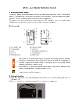
Preparation
Battery Installation and Replacement
1 Push down the battery cover lug to unhook it, and remove the cover.
2 Insert Battery BT-66Q in the direction matching connection points as shown in the illustration.
3 Mount two lugs on the RC-4R.
4 Push the battery cover lug down until the cover is locked.
Connection
points
Battery cover
Lug
Battery cover lug
BT-66Q

Preparation
12
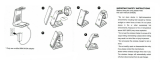
Installing RC-4R onto the Prism Unit A7R4
1 Match the receiving window with the front mark and insert the mounting hooks on the Prism
Unit A7R4 into the mounting holes of the RC-4R.
2 Turn the RC-4R towards the front mark (until you hear a click).
Front mark
Mounting hook
Mounting hole
Mounting hook (small)
Mounting hole
(small)

Preparation
13
Communication between the RC-4R and a Data Collector
Bluetooth communication
The Bluetooth module built-in the RC-4R enables wireless-communication with Bluetooth-compatible
equipment.
Serial signal connector
By connecting this connector to a PC or a data collector, it will provide the date transmission.
Mounting Remote Controller Handle Unit RC-4H onto the TS/IS/QS
If you wish to do turn-round motions, attach the remote controller handle unit RC-4H to the TS/IS/QS.
1 Dismount the handle from TS/IS/QS.
2 Match the handle unit mounting marks for the RC-4H and TS/IS/QS.
3 Make sure that the fixing knob is tightly fastened.
Note
Ensure that the power switch of TS/IS/QS is off when mounting RC-4H.
RC-4H
Handle unit
mounting mark
Handle

Basic Operation
14
Basic Operation
Power Switch ON
Press the power switch.
Power LED will light.
Battery Remaining Display
Push [ESC] key and the battery remaining capacity will be displayed for approximately 5 seconds.
Battery Warning Display for RC-4R
When the battery of the RC-4R is low, the power LED will flash with beep sound.
(Audio sound: Two pitches, frequent beep synchronized with power LED)
Confirm the battery remaining when turning on the instrument.
When the power LED is flashed with beep sound, replace or recharge the battery.
Battery Warning for TS/IS/QS series
When the battery power of TS/IS/QS in communication with RC-4R is low, the beep will sound from the RC-4R.
(Audio sound: Three pitches, frequent beep)
When the beep sounds, replace or recharge the batteries of TS/IS/QS.
Auto Power Off
If no key operation is given or no communication is performed for more than 30 minutes, the power turns off
automatically.
Error Display
The RC-4R unit does not display errors.
Refer to the operation manual for the data collector and other software for details.
Power LED
Power switch
Battery remaining display
Usable

Basic Operation
15
Setting for Communications with TS/IS/QS
The following settings is prerequisites for the communications to take place between the TS/IS/QS (or an
application program) and RC-4R.
The same RC channel / SS Wireless channel must be assigned to both RC-4R and the TS/IS/QS.
Refer to the TS/IS/QS instruction manual for the TS/IS/QS setup procedures.
Set the parameters in Setting Mode.
Refer to Table of item to be set in Setting Mode.
When connecting the RC-4R and data collector using Bluetooth, there are no settings for the RC-4R. Details
about procedures for connecting the data collector and RC-4R by Bluetooth, refer to the instruction manual for
the application software used on the data collector.
Connect a data collector to be used to the serial RS-232C connector of the RC-4R, and set the items as follows.
Refer to the instruction manual for the application software used on the data collector for the setup procedures.
With RC and SS-Wireless channels for the RC-4R, the parameters of the
application software used for the FC-250 or PC may be prioritized. For further
details, please refer to the instruction manual for your application software.
B.Rate
38400
Data.L
8
Parity
none
Stop Bit
1
Setting Parameters in TS/IS/QS
Setting Parameters in RC-4R
Setting Parameters of Bluetooth Communication port in Data Collector
Setting Parameters of Communication port in Data Collector

Basic Operation
16
Light Emitting Angle
Laser beams are emitted from the emitting window of the RC-4R.
The angle of emitting laser beams is as follows.
Important
RC-4R should be kept aiming so that the TS/IS/QS always stays within the
above range of laser beam emission until the turn-round motions are
completed.
If the aiming is out of above range while RC-4R is in turn-round motions, the
turn-round could not be completed.
Light emitting angle
Top view
Side view
At greater distances, the laser light at the edge of the beam field (angle) will be weaker.

Basic Operation
17
Light Detecting Range
The detecting angles of RC-4R and RC-4H (TS/IS/QS) are shown below:
TS/IS/QS can only be turned round with the turn-round key under the condition that RC-4R remains confined
within the range as shown below where RC-4H can detect light.
Important
Maintain the angle toward the TS/IS/QS within the range shown above until
the turn-round function is completed.
Turn-round function can be done within above range.
Top view
Side view
Detecting range
Detecting range
(RC-4H can detect the laser in all horizontal direction.)
RC-4H

Basic Operation
18
Turn-round Function
The turn-round key on RC-4R is used to have the TS/IS/QS search or automatically track RC-4R (prism).
Turn-round function is useful for auto-tracking when you start working or when the auto-tracking is interrupted
by any reason.
For increasing efficiency, keep the auto-tracking status when you move to another measurement point.
1 Turn on the TS/IS/QS and execute the [External Link].
2 Turn on the RC-4R by pressing the power switch.
3 Collimate the TS/IS/QS by using the sighting collimator on the RC-4R.
4 Press the [turn-round] key on the RC-4R.
TS/IS/QS starts searching and ends in the tracking mode.
Important
• Do not change the RC-4R direction during turn-round motions.
When the direction is changed, the detecting signal for TS/IS/QS moves and the prism
search cannot be performed correctly, causing a delay in the time required to complete
the search or preventing the search from being completed.
• At greater distances, the laser light at the edge of the emitting range (angle) will be
weaker; therefore, the RC-4R must be aimed correctly.
Note
The settings and conditions of communication are prerequisites for the communications
to take place between the TS/IS/QS and RC-4R.
Note
TS/IS/QS must be kept apart from reflecting planes such as glass and white walls. Reflected light
may prevent it from correct prism searching and from auto tracking. In this case, change the power
mode of RC-4R to the low power mode to decrease the output of laser beam. To change the power
mode, refer to “Low Power Mode of Laser Beam” on page 19.
/