Approximate Install Time: 60 minutes
Durée approx. de l’installation : 60 min.
Tiempo aproximado de instalación: 60 min
READ THIS FIRST:
Read and follow all vehicle warnings and
installation instructions before beginning
installation. Wear safety glasses and use all safety
precautions during installation
.
LISEZ CECI EN PREMIER:
Lire et observer toutes les consignes de sécurité et
les instructions avant de commencer l’installation.
Durant l’installation, veiller à toujours porter des
lunettes de protection et respecter les mesures de
sécurité.
LEA ESTO PRIMERO:
Lea y siga todas las advertencias e instrucciones de
instalación del vehículo antes de empezar la
instalación. Use gafas de seguridad y todas las
precauciones de seguridad durante la instalación.
INSTALLATION
INSTRUCTIONS
119250-037 Rev C 05/15
www.cequentgroup.com
Technical Assistance: 800-632-3290
TESTING:
• When using a volt meter or circuit tester, carefully probe one wire at a time.
CAUTION Do not probe across two wires or across vehicle structure.
• Determine type of Vehicle wiring system and location of required input functions.
• Determine each of the tow vehicle inputs as shown in the illustration.
ENGLISH
WARNING
Overloading circuit can cause res. DO NOT exceed
lower of towing manufacturer rating or:
• Max. stop/turn light: 2 per side (4.2 amps)
• Max. tail lights: (7.5 amps)
Read vehicle’s owners manual & instruction sheet for
additional information.
AVERTISSEMENT
La surcharge du circuit peut provoquer des incendies.
NO exceda inferior entre la calicación del fabricante
del remolque o:
• Feux de freinage/direction (max.) :
2 par côté (4,2 A)
• Feux arrière (max.): (7,5 A)
Consulter le manuel du propriétaire du véhicule et
le feuillet d’instructions pour plus de renseignements.
ADVERTENCIA
Sobrecargar el circuito puede provocar incendio. NO exceda
inférieure de remorquage note fabricant ou:
• Máx. luz de freno/giro : 2 por lado (4.2 amps)
• Máx.luces traseras: (7.5 amps)
Lea el manual del propietario del vehículo y la hoja de
instrucciones para información adicional.
©2015 Cequent™ Performance Products
HARDWARE OVERVIEW / APERÇU DE LA QUINCAILLERIE / REPASO DE LAS PIEZAS:
*Cable Tie, 8.5” (20)
Attache de câble, 8.5 po (20)
Amarre de cable 8.5” (20)
*Cable Tie, 14.5” (1)
Attache de câble, 14.5 po (1)
Amarre de cable 14.5” (1)
Foam Tape (4)
Ruban de mousse (4)
Cinta de espuma (4)
15 AMP Fuse (1)
Fusible 15 ampères (1)
Fusible de 15 amperios (1)
*Ring Terminal (1)
Cosse à anneau (1)
Terminal de anillo (1)
*Fuse Holder (1)
Porte-fusibl (1)
Portador de fusibles (1)
*Yellow Butt Connector (2)
Connecteur d’about jaune (2)
Conector de culata amarilla (2)
Self-Tapping Screw (1)
Vis autotaraudeuse (1)
Tornillo Autorroscante (1)
REQUIRED TOOLS / OUTILS REQUIS / HERRAMIENTAS NECESSARIAS:
Phillips Head #2 Screwdriver
Tournevis Phillips #2
Destornillador de estrella (Philips) #2
Wire Cutters
Coupe-ls
Cortadores de cable
Tester or Volt Meter
Multimètre ou Voltmètre
Probador o Voltímetro
Wire Strippers/ Wire Crimpers
Outils à dénuder/Sertisseurs
Pelacables/ Plegadores de cable
Socket & Ratchet Set
Juego de Ratchet y Dados
Socket et cliquet ensemble
Drill (3/32” Drill Bit)
Taladro con broca 3/32”
Perceuse (foret avec 3/32 “)
Trailer Tow Fuse - 15 AMP MAX
This vehicle is equipped with a ZCI
ModuLite. ZCI requires constant 12V
power. If interrupted, ZCI may need to
be reset.
See ZCI reference card or http://www.
tekonsha.com/support/installation
/N119250.pdf for required steps.
1-800-632-3290 17499-xxx Rev 1
Double Sided Tape (1)
Ruban double-face (1)
Cinta de dos caras (1)
* Item not included in 119250. Wire kit 118150 or 118151 sold separately. / Article non inclus dans l’ensemble 119250. Ensemble de câblage 118150 ou 118151
vendu séparément. / Elemento no incluido en 119250. El kit de cables 118150 o 118151 se vende por separado.
*Power Wire (1)
Fil d’alimentation (1)
Cable de alimentación (1)
Reference Card (1)
Carte de référence (1)
Tarjeta de referencia (1)
Notice Label (1)
Étiquette d’avis (1)
Etiqueta de aviso (1)
www.tekonsha.com
Vehicle Wiring Code & Description Description of Vehicle’s Electrical System Input Wires Used Input Wires Exceptions
A - 2 wire system The vehicle’s turn & brake functions are combined on one
wire and the tail light function is on a separate wire.
Yellow to vehicle Left Turn/Brake wire, Green to vehicle
Right turn/Brake wire & Brown to vehicle Tail wire.
Brake wire (red) is not used.
B - 3 wire system The vehicle’s turn, brake and tail light function are on
separate wires.
Yellow to vehicle Left Turn wire, Green to vehicle Right
turn wire, Brown to vehicle Tail wire & Red to vehicle
Brake wire.
NONE - Use all wires.
BT - Brake/Tail multiplexed wiring
system
The vehicle’s brake & tail functions are combined on one
wire and the turn functions are on separate wires.
Yellow to vehicle Left Turn wire, Green to vehicle Right
turn wire & Red to vehicle Brake/Tail wire.
Tail wire (brown) is not used.
BTT - Brake/Tail/Turn multiplexed
wiring system*
The vehicle’s brake, tail & turn functions are combined on
one wire.
Yellow to vehicle Brake/Tail/Left Turn wire & Green to
vehicle Brake/Tail/Right turn wire.
Tail wire (brown) & Brake wire (red)
are not used.
INPUT SENSOR – DETERMINATION:
* Module may not work with some BTT wiring systems. To alleviate, you may need to route tail wire to rear license plate illumination circuit and/or brake to center high stop light.
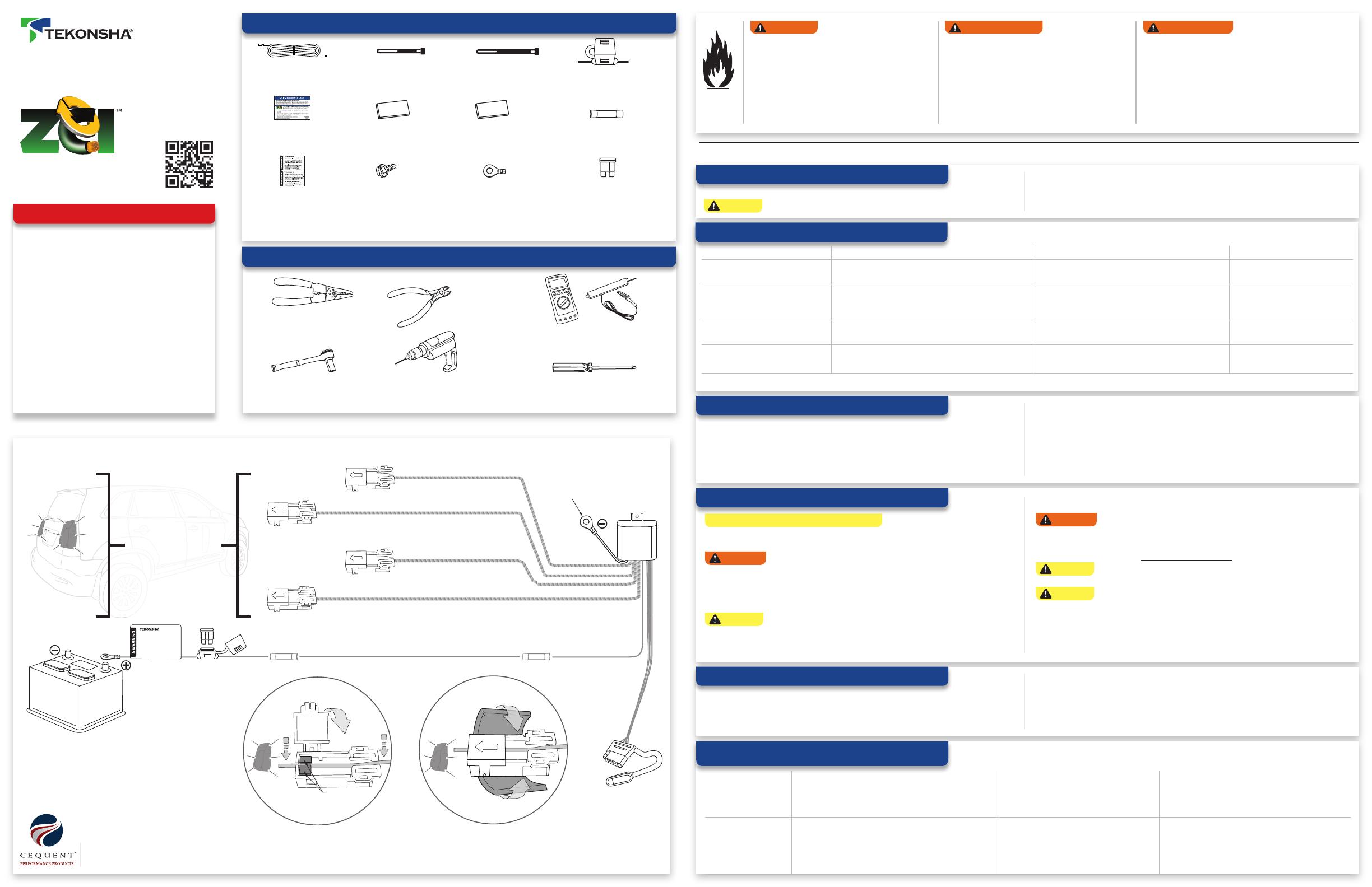
INPUT SENSOR – INSTALLATION:
• Apply required input sensors, as determined in the previous step.
• Ensure sensor end is orientated correctly. The arrow on the lid should be pointing towards
the vehicle’s light.
• Lay the wire between the sensor’s ferrites and snap the lid closed. See Figure A.
• G code (Low Side Switched) vehicles: For all used input sensors, the arrow will be pointing
away from the vehicle’s light.
• Secure all sensor ends with foam tape. Ensure ends will not move around during operation.
See Figure B.
HARNESS INSTALLATION:
NOTE: Required wiring kit may be sold separately
• Determine mounting location of the module. Secure using the double-sided tape provided.
Using butt connector, connect module’s black wire and 12 gauge (or larger gauge) wire.
WARNING Make sure module is mounted so that the epoxy side of the module is
pointed towards the ground to prevent any water buildup.
• Locate a suitable grounding point near the module such as an existing ground stud or drill a
3/32” hole and secure the white wire using the eyelet and screw provided. (Do not drill into
vehicle oor or bed.) Clean dirt and rustproong from area.
CAUTION Verify what is behind any surface prior to drilling to avoid damage to the
vehicle and/or personal injury. Do not drill into any exposed surfaces.
• Disconnect and isolate the vehicle’s negative battery terminal.
WARNING Read and follow all warnings and cautions printed on the tow vehicle’s
battery.
• Route wire to vehicle’s positive side of battery. Using fuse holder, butt connector and ring
terminal, connect to battery. DO NOT insert 15 amp fuse.
CAUTION Module must be connected to a constant power source. Do not use an
alternative power source that is interrupted when the vehicle is o.
CAUTION Route the wire being careful to avoid any hot pipes, heat shields, the fuel
tank or any other points that may pinch or break the wire.
• Wrap notice label around yellow fuse holder wire, near ring terminal.
• Secure harness with the cable ties provided, to prevent damage or rattling.
• Reconnect the vehicle’s Negative (-) battery cable.
MODULE LEARN MODE AND VERIFICATION:
• Start vehicle and turn all functions o: Tail (head lights), brake and turns. Initiate ZCI learn
mode by inserting 15 amp fuse into fuse holder.
• Activate each function separately for approximately 5 seconds (Tail, brake, right turn and
left turn).
• Test and verify installation with a test light or trailer.
• Hand ZCI Reference card to vehicle owner or place in glove box.
No Power to 4-Flat or
outputs not func-
tioning properly.
Remove 15 amp fuse and repeat Module learn mode and
verication steps.
Ensure sensors are installed per the Input
Sensor – Determination ndings. Remove 15
amp fuse and repeat Module learn mode and
verication steps.
Ensure sensor ends are installed and orientated prop-
erly. Repeat input sensor installation steps. Remove
15 amp fuse and repeat Module learn mode and
verication steps.
No Power to 4-Flat Ensure 15 amp fuse is fully inserted into fuse holder. Fuse
should have no breaks. Fuse holder connected properly to
positive post of battery. Remove 15 amp fuse and repeat
Module learn mode and verication steps.
Check chassis ground. Ensure ring terminal is
in full contact with bare metal of the vehicle’s
chassis. Remove 15 amp fuse and repeat
Module learn mode and verication steps.
TROUBLE SHOOTING GUIDE:
15 AMP
15 A
TOW VEHICLE INPUTS / ENTRÉES DU VÉHICULE DE REMORQUAGE / ENTRADAS DEL VEHÍCULO REMOLCADOR
SEE
INPUT SENSOR
DETERMINATION
STEP
VOIR L’ÉTAPE DE LA
DÉTERMINATION DU
CAPTEUR D’ENTRÉE
VER EL PASO DE
DETERMINACIÓN DEL
SENSOR DE ENTRADA
CHASSIS GROUND
PRISE DE MASSE DU
CHÂSSIS
MASA DE CHASIS
MODULE
MODULE
MÓDULO
POWER WIRE / FIL D’ALIMENTATION / C ABLE DE ALIMENTACIÓN
4FLAT HARNESS
FAISCEAU PLAT
À 4 VOIES
ARNÉS PLANO
DE 4 VÍAS
FIGURE A
FIGURA A
FIGURE B
FIGURA B
REAR VEHICLE LIGHTS
FEUX ARRIÈRE DU
VÉHICULE
LUCES TRASERAS DEL
VEHICULO
BROWN STICKER = TAIL
AUTOCOLLANT BRUN = ARRIÈRE
CALCOMANÍA MARRÓN = LUZ TRASERA
YELLOW STICKER = LEFT TURN
AUTOCOLLANT JAUNE = VIRAGE À GAUCHE
CALCOMANÍA AMARILLA = DIRECCIONAL IZQUIERDA
RED STICKER = STOP
AUTOCOLLANT ROUGE = ARRÊT
CALCOMANÍA ROJA = FRENO
GREEN STICKER = RIGHT TURN
AUTOCOLLANT VERT = VIRAGE À DROITE
CALCOMANÍA VERDE = DIRECCIONAL DERECHA
Ferrites
Ferritas


