Page is loading ...

®
Badger Meter Europa GmbH
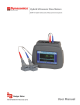
PortaSonic 9000
User manual
August 2011
UF_PS9000_BA_02_1108

Contents Page
UF_PS9000_BA_02_1108
1. Principle of measurement ................................................................................................. 1
2. PortaSonic 9000 and components .................................................................................... 2
2.1 Converter ................................................................................................................. 2
2.2 Ultrasonic sensors ................................................................................................... 2
2.3 Mounting material and accessories ......................................................................... 3
2.3.1 Connecting cables for ultrasonic sensors and converter............................ 3
2.3.2 Mounting rail for the ultrasonic sensors XUC (I)-PW.................................. 3
2.3.3 Fastening chains for ultrasonic sensors ..................................................... 3
2.3.4 Ultrasonic coupling gel ............................................................................... 4
2.3.5 Temperature probe PT100 ......................................................................... 4
2.3.6 Analogue output cable 4-20mA (4 alligator clips) ....................................... 4
2.3.7 Connecting cable for the internal potential-free relay (2 crocodile clips) .... 4
2.3.8 Power supply unit (100-240V, 47-63Hz, 1A) .............................................. 4
2.4 The interfaces .......................................................................................................... 5
2.5 Scope of supply of the PortaSonic 9000 delivery package ...................................... 6
2.6 Safety instructions .................................................................................................... 6
3. Operation ............................................................................................................................ 7
3.1 Control keys on the meter ........................................................................................ 7
3.2 Basic operation/navigation ....................................................................................... 7
4. Initial start ........................................................................................................................... 8
4.1 Basic setting, navigation to the main menu ............................................................. 8
4.1.1 Adjusting the display language .................................................................. 8
4.1.2 Adjusting the time and date ........................................................................ 8
4.1.3 Navigation to the main menu ..................................................................... 9
4.1.4 The information headline .......................................................................... 10
5. Preparation of the measurement .................................................................................... 11
5.1 Inlet and outlet distances ....................................................................................... 11
5.2 Mounting positions of the ultrasonic sensors ......................................................... 11
5.2.1 General information on the installation of the ultrasonic sensors ............. 11
5.2.2 Installation of the ultrasonic sensor on horizontal pipelines ..................... 12
5.2.3 Ultrasonic sensors on uneven surfaces ................................................... 12
5.3 Installation of the ultrasonic sensors ...................................................................... 13
5.3.1 V mode ..................................................................................................... 13
5.3.2 W mode .................................................................................................... 13
5.3.3 Z mode ..................................................................................................... 13
6. Metering with the PortaSonic 9000 ................................................................................. 14
6.1 Parametering ......................................................................................................... 14
6.1.1 Basic information on the parametering .................................................... 14
6.2 What has to be parameterized? ............................................................................. 14
6.3 Parametering by means of the Quick-Setup .......................................................... 15
6.4 Sensor installation/Sensor distance ....................................................................... 20
6.4.1 Distance for V or W mode ........................................................................ 20
6.4.2 Distance of the ultrasonic sensors – Z mode ........................................... 20
6.4.3 Installation of the ultrasonic sensors by means of a mounting rail ........... 21
6.5 Parameter editing via the main menu .................................................................... 23
6.6 Parameter editing by zero adjustment ................................................................... 25

Contents Page
UF_PS9000_BA_02_1108
6.7 Heat quantity measurement ................................................................................... 26
6.7.1 Introduction ............................................................................................ 26
6.7.2 Installation of the PT100 ........................................................................ 27
6.7.3 Zero adjustment of the PT100 ............................................................... 28
7. Measuring windows of the PortaSonic 9000 ................................................................. 28
7.1 Main measuring window: „Flow 1“ ......................................................................... 28
7.2 „Flow 2“ measuring window ................................................................................... 29
7.3 „Heat quantity“ measuring window ......................................................................... 30
7.4 Unit selection ......................................................................................................... 30
7.4.1 Selection of the flow unit ........................................................................ 31
7.5 Selection of the flow meter unit .............................................................................. 31
7.5.1 Selection of the heat energy unit ........................................................... 31
7.5.2 Selection of the heat capacity unit ......................................................... 32
8. Data storage/loading and administration ....................................................................... 33
8.1 Data logging ........................................................................................................... 33
8.2 Time-controlled data recording .............................................................................. 33
9. Parametering of the inputs and outputs ........................................................................ 35
9.1 Parametering of the 4-20mA outputs ..................................................................... 35
9.2 Colour coding of the 4-20mA output cable ............................................................. 36
9.3 Parametering of the relay ....................................................................................... 38
9.4 Colour coding of the relay output cable ................................................................. 38
10. Calibration ....................................................................................................................... 41
10.1 Flow calibration ...................................................................................................... 41
10.2 Calibration of the PT100 ........................................................................................ 41
11. System setup .................................................................................................................. 42
11.1 Change of time and date ........................................................................................ 42
11.2 Change of “Background lighting“ ........................................................................... 42
11.3 Change of the menu language ............................................................................... 43
11.3.1 System setup of „Other“ ......................................................................... 43
12. Troubleshooting ............................................................................................................. 44
12.1 What to do if the pipeline is not completely filled up? ............................................ 45
12.2 The diagnostic windows of the PortaSonic 9000 ................................................... 46
13. Maintenance .................................................................................................................... 48
13.1 Opening the meter ................................................................................................. 48
13.2 Changing the SD memory card .............................................................................. 49
13.3 Changing the backup battery ................................................................................. 49
13.4 Connecting the analogue outputs with externally fed supply points....................... 50
14. Medium data ................................................................................................................... 51
15. Technical data ................................................................................................................ 54
16. Approvals / EMC ............................................................................................................. 55

Principle of measurement 1 / 55
UF_PS9000_BA_02_1108
Ultrasonic
sensor
1. Principle of measurement
The PortaSonic 9000 uses the highly precise ultrasonic transit-time measuring principle,
for which two ultrasonic sensors are externally mounted on the pipeline and connected
with the electronic. The ultrasonic sensors alternately work as transmitter and receiver
and mutually send ultrasonic signals. During these transmissions, the respective signal
transit times of the to-and-from signals (t1, t2) are measured. The electronic of the
PortaSonic 9000 measures the difference of the transit time of the ultrasonic signals going
with and against the direction of flow t1 and t2. These signals are either decelerated or
accelerated by the medium flow. The difference produced in both signal transit times is
proportional to the flow rate and will be used together with the pipeline geometry for a
precise flow calculation.
Signal cable
Converter
USB interface
4 to 20 mA/pulse

PortaSonic 9000 and components 2 / 55
UF_PS9000_BA_02_1108
2. PortaSonic 9000 and components
Illustration 1: PortaSonic 9000 – Mounted ultrasonic sensors (below) and converter
Your PortaSonic 9000 mainly consists of the ultrasonic sensors mounted on your pipeline
system and of a converter.
2.1 Converter
The converter ensures the signal processing and makes the measurement results
available to the user.
2.2 Ultrasonic sensors
The ultrasonic sensors are externally mounted on the pipeline and both produce and
receive the ultrasonic signals by which the flow recorded through the converter can
be determined.
Ultrasonic sensor XUC PW 20 (2 MHz), colour of housing: RED, for pipe diameters
DN10…DN100, temperatures: -40°C…150°C
Ultrasonic sensor XUC PW 10 (1 MHz), colour of housing: BLUE, for pipe
diameters: DN32…DN400, temperatures: -40°C…150°C
Ultra sensor XUC-PW 5 (0.5 MHz), color of housing: GREEN, for pipe diameters
DN200…DN6000, temperatures: -40°C…80°C (150°C optional) – depending on the
sonsor fixation (material)

PortaSonic 9000 and components 3 / 55
UF_PS9000_BA_02_1108
2.3 Mounting material and accessories
2.3.1 Connecting cables for ultrasonic sensors and converter
Illustration 2: Signal cables
2.3.2 Mounting rail for the ultrasonic sensors XUC PW
For PW 10 and PW 20 (the ultrasonic sensor XUC-PW F5
will be installed on the pipeline without using a mounting rail).
Illustration 3: Mounting rail
2.3.3 Fastening chains for ultrasonic sensors
Illustration 4 Fastening strap for the ultrasonic sensor XUC-PW5
Illustration 5 Ultrasonic sensor for large pipelines – textile mounting belt for the sensor mounting

PortaSonic 9000 and components 4 / 55
UF_PS9000_BA_02_1108
2.3.4 Ultrasonic coupling gel
The ultrasonic coupling gel will be applied between the ultrasonic sensor
and the pipe to ensure the optimum signal input.
2.3.5 Temperature probe PT100
For the heat or cold quantity calculations, the temperatures within the
heating or cooling circuits are measured by means of temperature probes
to be buckled on.
2.3.6 Analogue output cable 4-20mA (4 alligator clips)
By means of the analogue output cable, it is possible, for example, to
connect an external recorder to your converter to transmit measured values
like flow, heat capacity, etc.
2.3.7 Connecting cable for the internal potential-free relay (2 crocodile clips)
By means of the relay connecting cable, it is possible, for example, to
connect an external recorder to your converter in order to transmit counting
values like volume or heat quantity.
2.3.8 Power supply unit (100-240V, 47-63Hz, 1A)
The power supply unit is usually used to load the rechargeable battery. It is
of course also possible to use it for a continuous mains supply of your
PortaSonic 9000.

PortaSonic 9000 and components 5 / 55
UF_PS9000_BA_02_1108
2.4 The interfaces
On the backside of the PortaSonic 9000, you can find the inputs and
outputs.
1 Constant voltage supply input
The enclosed mains adapter will be connected to this terminal to ensure
the constant voltage supply of the PortaSonic 9000.
2 Interface USB 2.0 (mini USB socket, type B)
ensures the access by means of a PC to the integrated SD memory
card where data on the metering points and on the measurements
(LOG files) are stored. From Windows
®
Version XP and up, the internal
SD memory card will be recognized as a mass storage unit. Therefore,
additional drivers are not required.
3 + 4 Inputs for the ultrasonic sensors (BNC)
These are the terminals for the ultrasonic transducers.
5 Relay output (4-pole mini DIN)
This output is potential-free and NO (normally open). Only when
activated, the internal contact will be closed. Therefore, it can be used
for alarms or for upper/lower limit deviations.
6 T1/T2 inputs for PT100 (6-pole mini DIN)
for connecting the optional temperature sensors to use the PortaSonic’s
internal heat quantity measurement.
7 4-20mA analogue outputs (5-pole mini DIN)
It is possible to allocate variable quantities to these outputs like, for
example, the flow. They will supply a current, which is proportional to
the value of the respective variable quantity. It is also possible to
configure the initial and final values. These terminals are two active
double-conductor outputs.
1
2
3
4 5 6 7
Power
18,5 VDC
USB
Down
Up
T1/T2
Relais
Analog Out
PortaSonic 9000

PortaSonic 9000 and components 6 / 55
UF_PS9000_BA_02_1108
2.5 Scope of supply of the PortaSonic 9000 delivery package
• Hard suitcase
• Converter
• Mains adapter including mains cable
• Signal cable (between converter and ultrasonic sensor)
• Ultrasonic sensor (type according to the customer order)
• Mounting rail for the ultrasonic sensor
• Analogue output cable for 4-20mA output (MiniDIN, crocodile clips)
• Digital output cable for the relay output (MiniDIN, crocodile clips)
• Stainless steel fastening chains (up to DN400)
• Ultrasonic coupling gel
Optionally, further ultrasonic sensors for smaller/larger pipe sizes are available as
well as temperature probes to be buckled on.
2.6 Safety instructions
The operating temperatures of the converter should not exceed or fall below a
temperature range of -20°C up to 60°C!
The ultrasonic sensors are susceptible to shocks and vibrations. Therefore, please
ensure that the sensors are neither exposed to strong vibrations nor to intense
mechanical shocks. The sensors may already be destroyed beyond repair after
one single unintentional drop!
The power supply unit should only be used indoors!
Replace the power supply unit or the 230V mains cable completely in case of a
mechanical or electrical damage!
Instructions for the operation in ATEX explosion-proof zones:
The converter and the standard ultrasonic sensors are not suitable for use in
explosion-proof zones!
Do not use the ultrasonic sensors above or below the permissible medium
temperature range!

Operation 7 / 55
UF_PS9000_BA_02_1108
3. Operation
3.1 Control keys on the meter
Switches the meter on/off.
Switches the backlight on/off.
Multifunctional keys: Select a function displayed on the screen by means of
the key located beside the respective display.
3.2 Basic operation/navigation
Please use the multifunctional keys:
Direction keys for navigation
Acknowledges the entry
Acknowledges the entry and switches to the next window
Back to the previous window
Increases the value
Reduces the value
Releases the XYZ function (variable function according to the
respective application)
Without function
XYZ
3
2 1
1
2
3

Initial start 8 / 55
UF_PS9000_BA_02_1108
4. Initial start
4.1 Basic setting, navigation to the main menu
4.1.1 Adjusting the display language
1. Switch on the meter and push the multifunctional key beside the field
„SETUP LANG.“
2. Select the respective language within the appearing window by means of
he arrow keys. Acknowledge your entry with the „Enter“ key.
You can alter the language within the menus by adjusting the language.
The language within the fields beside the multifunctional keys, however, will
remain unchanged.
4.1.2 Adjusting the time and date
After having selected your language, you are now in the main menu of the
meter.
1. Now, select „System setting“ by means of the arrow keys.
2. Then, select „Time and date“

Initial start 9 / 55
UF_PS9000_BA_02_1108
3. Enter the time by using the format hour (hh) : minute (mm) : second (ss).
Then, enter the date by using the format day (dd) : month (mm) : year
(yy).
4.1.3 Navigation to the main menu
After having switched on your PortaSonic 9000 and the display of the start
screen, the measurement window “Flow 1” will appear automatically after a
few seconds.
The measurement window „Flow 1“ shows an overview of all necessary
information for the flow and for the heat quantity measurement.
1. Now, select „Setup“
2. When you see this window, select „CMPL. Setup“.

Initial start 10 / 55
UF_PS9000_BA_02_1108
3. You are now in the main menu from which you can select all necessary
functions of your device.
4. In order to return to the measurement window, press „ESC“ and „MEAS“
in the subsequent window.
Now, you know the basic operations of your PortaSonic 9000.
4.1.4 The information headline
Time: Indicates the current time, which is also the system time.
During the later logging procedure, the measured data
will be provided with a time stamp by the system time.
SD Memory: Indicates the remaining storage capacity of the internal
SD memory card (standard 2 GB).
Accu.: Informs about the rechargeable battery status, like:
Load: Meter is supplied by the power supply unit, if necessary,
the rechargeable battery will be loaded.
Full: The rechargeable battery is fully loaded. In case of a
deactivated display lighting, the meter can be operated
with a lighted display for approx. 3 hours and for
approx. 5 hours without lighting.
Percentage display: Indicates the loading state of the rechargeable
battery.
The indicated time always refers to a new rechargeable battery.
Depending on the rechargeable battery age and on the frequency
of the use/load cycles, the actual time may differ from the time
indicated.
To reach the main menu more quickly after having switched on the meter,
select „SETUP“ already during the start sequence and „COMPL. SETUP“
in the next window.

Preparation of the measurement 11 / 55
UF_PS9000_BA_02_1108
5. Preparation of the measurement
Please take into consideration the following aspects to ensure a successful flow
measurement.
5.1 Inlet and outlet distances
The place, where the meter is mounted, will have a considerable influence on the
measurement quality. Especially, the inlet and outlet distances should be taken into
account. Therefore, see the following table:
5.2 Mounting positions of the ultrasonic sensors
5.2.1 General information on the installation of the ultrasonic sensors
At the mounting position, the pipe must always be completely filled up
(pressure pipe)!
Measurements on only partially filled pipes are not possible!
The ultrasonic sensors can be mounted vertically, horizontally or in any other
position. It is, however, indispensable to observe the possible mounting positions
mentioned below:
Reduc-
tion
90° bend
T-piece
Enlarge-
ment
Valves
Pump
Partitioning
U
p
stream
Downstream
Upstream control valve Downstream control valve
Stop valve
Return valve
Pump
Sensors

Preparation of the measurement 12 / 55
UF_PS9000_BA_02_1108
The illustration shows the side view of the pipeline.
5.2.2 Installation of the ultrasonic sensor on horizontal pipelines
In case of an horizontal pipeline, we recommend to install the sensor
approx. +/-45% offset the horizontal plane surface, because it might be
possible that bubbles will form in the upper part of the pipeline and
sediments in the lower part.
A
Illustration 2: Installation of the ultrasonic sensors – positioning (1)
5.2.3 Ultrasonic sensors on uneven surfaces
Avoid the installation of the ultrasonic sensors on uneven surfaces like
weldings or deformations. Try as far as possible to remove thick and
uneven protective coatings of paint from the pipe locations on which you
intend to install your ultrasonic sensors.
Illustration 3: Installation of the ultrasonic sensors – positioning (1)
Good
Good
Cannot be completely filled up
Air is accumulating
Cannot be
completely
filled up
Pump
Air bubbles
Pipe
Horizontal
level
Sediments
Welding
Welding
Welding within measuring range
Welding outside measuring range
Welding partially within measuring
range
Welding outside measuring range

Preparation of the measurement 13 / 55
UF_PS9000_BA_02_1108
5.3 Installation of the ultrasonic sensors
This chapter will inform you on the possible ways to install your ultrasonic sensors.
The V mode is the standard way of installation for most applications.
5.3.1 V mode
Ultrasonic sensor 1 Ultrasonic sensor 2
Concerning the V mode, both ultrasonic sensors are mounted on the same side of
the pipe. In case of small and medium-size pipeline systems, the V mode is the
standard way of installation reflecting the ultrasonic signal via the pipe wall.
5.3.2 W mode
Ultrasonic sensor 1 Ultrasonic sensor 2
The W mode is a special way of mounting your ultrasonic sensors usually applied, if
necessary, for small and very small-size pipeline systems.
5.3.3 Z mode
Ultrasonic sensor 1
The Z mode is also a special way to install your ultrasonic sensors. On account of
the short signal transmission way, compared to the V and W mode, this installation
mode is usually chosen in case of large pipeline systems or when the medium to be
measured is highly contaminated or loaded with gas.
Ultrasonic sensor 2

Metering with the PortaSonic 9000 14 / 55
UF_PS9000_BA_02_1108
6. Metering with the PortaSonic 9000
The flow metering is carried out in 5 steps:
1) Choose the appropriate position to install your ultrasonic sensors
2) Parameterize your PortaSonic 9000
3) Mount the ultrasonic sensors on your pipeline system
4) Adjust the zero point
5) Start the flow measurement
6.1 Parametering
6.1.1 Basic information on the parametering
The chapter „Parametering“ describes how to enter all the data which are
required for the flow metering.
1. The „Quick Setup“: By means of the Quick Setup, the PortaSonic 9000
will lead you step by step through all the functions necessary for the
parametering. The Quick Setup will be sufficient for most of the existing
applications and ensures a fast and efficient parametering within a very
short period of time.
2. The „Compl. Setup“: The complete setup allows the selection of all
existing functions and even expert setting.
6.2 What has to be parameterized?
1. The outside diameter of the pipe or the pipe circumference
2. The pipe wall thickness; in case of lined pipes, also the lining material and the
thickness of the lining.
3. The pipe material
4. The medium to be measured
5. The appropriate ultrasonic sensor
6. The installation mode applied for the ultrasonic sensors
The ultrasonic metering is using the transit time measuring principle. The ultrasonic
signals penetrate both the pipeline and the medium. For the calculation of the signal
transit-time, the sound speed, the wall thickness and the pipe diameter or
circumference are allocated to each medium and to each pipe material or pipe
lining, if necessary. The meter has some internally stored tables containing the
respective sound speeds of different materials and media. If your material or
medium is not listed in these tables, you will have to enter the appropriate sound
speed value by hand. At the end of this instruction manual, you will find the
corresponding tables with the data on the medium.

Metering with the PortaSonic 9000 15 / 55
UF_PS9000_BA_02_1108
1
6.3 Parametering by means of the Quick-Setup
The following steps are necessary to reach the “Parametering” function:
After having switched on your device, select „Setup“ during the start sequence and
then „Quicksetup“.
Select „Setup“ and afterwards „Quicksetup“ in the main measurement window „Flow
1“.
Start
Select, if you want to enter the pipe circumference or
the outside diameter of the pipe:
Enter the outside diameter of the Enter the pipe circumference.
pipe.
OR

Metering with the PortaSonic 9000 16 / 55
UF_PS9000_BA_02_1108
Enter the wall thickness of the pipeline.
If you do not know the wall thickness, we recommend to use a wall thickness
measuring device. It is also recommended to use such a device for pipelines with
extensive furring.
Select the pipe material.
Select the pipe Enter the sound velocity
material from the data of the pipe material.
base.
Does a pipe lining exist? YES/NO
2
3
4
OR

Metering with the PortaSonic 9000 17 / 55
UF_PS9000_BA_02_1108
NO
YES
Enter the thickness
of the lining.
Choose between the database
and the user entry for entering
materials not listed by
the database
Select the material of the Enter the sound of speed
pipe lining from the of the pipe lining material
database.
5
OR
OR
/