Page is loading ...


Disclaimers
Important Notice
Copyright©SolarEdgeInc.Allrightsreserved.
Nopartofthisdocumentmaybereproduced,storedinaretrievalsystemortransmitted,inanyformor
byanymeans,electronic,mechanical,photographic,magneticorotherwise,withoutthepriorwritten
permissionofSolarEdgeInc.
Thematerialfurnishedinthisdocumentisbelievedtobeaccurateandreliable.However,SolarEdge
assumesnoresponsibilityfortheuseofthismaterial.SolarEdgereservestherighttomakechangestothe
materialatanytimeandwithoutnotice.YoumayrefertotheSolarEdgewebsite
(https://www.solaredge.com/us/)forthemostupdatedversion.
Allcompanyandbrandproductsandservicenamesaretrademarksorregisteredtrademarksoftheir
respectiveholders.
Patentmarkingnotice:seehttps://www.solaredge.com/us/patent
ThegeneraltermsandconditionsofdeliveryofSolarEdgeshallapply.
Thecontentofthesedocumentsiscontinuallyreviewedandamended,wherenecessary.However,
discrepanciescannotbeexcluded.Noguaranteeismadeforthecompletenessofthesedocuments.
Theimagescontainedinthisdocumentareforillustrativepurposesonlyandmayvarydependingon
productmodels.
FCC Compliance
Emission Compliance
ThisequipmenthasbeentestedandfoundtocomplywiththelimitsforaClassBdigitaldevice,pursuant
topart15oftheFCCRules.Thisequipmenthasbeentestedandfoundtocomplywiththelimitsapplied
bythelocalregulations.Theselimitsaredesignedtoprovidereasonableprotectionagainstharmful
interferenceinaresidentialinstallation.Thisequipmentgenerates,usesandcanradiateradiofrequency
energyand,ifnotinstalledandusedinaccordancewiththeinstructions,maycauseharmfulinterference
toradiocommunications.However,thereisnoguaranteethatinterferencewillnotoccurinaparticular
installation.Ifthisequipmentdoescauseharmfulinterferencetoradioortelevisionreception,whichcan
bedeterminedbyturningtheequipmentoffandon,youareencouragedtotrytocorrectthe
interferencebyoneormoreofthefollowingmeasures:
lReorientorrelocatethereceivingantenna.
lIncreasetheseparationbetweentheequipmentandthereceiver.
lConnecttheequipmentintoanoutletonacircuitdifferentfromthattowhichthereceiveris
connected.
lConsultthedealeroranexperiencedradio/TVtechnicianforhelp.
Changesormodificationsnotexpresslyapprovedbythepartyresponsibleforcompliancemayvoidthe
user’sauthoritytooperatetheequipment.
Disclaimers
-Three Phase Inverter with Synergy Technology Installation MAN-01-00402-1.4
1

Contents
Disclaimers 1
ImportantNotice 1
FCCCompliance 1
EmissionCompliance 1
Support and Contact Information 5
HANDLING AND SAFETY INSTRUCTIONS 7
SafetySymbolsInformation 7
IMPORTANTINVERTERSAFETYINSTRUCTIONS 7
Chapter 1: Introducing the SolarEdge Power Harvesting System 10
PowerOptimiser 10
ThreePhaseInverterwithSynergyTechnology 11
MonitoringPlatform 12
SupportedACGrids 12
InstallationProcedure 12
InstallationEquipmentList 13
Chapter 2: Installing the Power Optimisers 14
Safety 14
PackageContents 15
InstallationGuidelines 15
Step1:MountingandGroundingthePowerOptimizers 16
Step2:ConnectingaPVModuletoaPowerOptimiser 19
Step3:ConnectingPowerOptimisersinStrings 19
Step4:VerifyingProperPowerOptimiserConnection 21
Chapter 3: Installing the Primary and Secondary Unit(s) 22
PrimaryUnitPackageContents 22
SecondaryUnitPackageContents 22
IdentifyingtheUnits 22
PrimaryUnitInterface 22
ConnectionUnitInterface 26
SecondaryUnitInterface 27
OpeningConduitDrillGuides 27
MountingandConnectingthePrimaryandSecondaryUnit(s) 29
Chapter 4: Connecting the AC and DC Strings to the Connection Unit 37
ConnectingtheACGridtotheConnectionUnit 37
ConnectingtheACGridandGroundingtotheConnectionUnit 37
ConnectingtheStringstotheConnectionUnit 39
SettingtheInvertertoSupport208V3-wireGrid 41
Chapter 5: Activating, Commissioning and Configuring the System Using the Inverter SetApp 42
Step1:ActivatingtheInstallation 42
Step2:CommissioningandConfiguringtheInstallation 43
SettingCountryandLanguage 43
Pairing 43
Communication 44
-Three Phase Inverter with Synergy Technology Installation MAN-01-00402-1.4
2

PowerControl 44
DeviceManager 45
Maintenance 45
Information 46
Step3:VerifyingProperActivationandCommissioning 47
ViewingSystemStatus 47
MainInverterStatus 47
SiteStatus 49
CommunicationStatus 51
InverterEnergyStatus 52
MeterStatus 52
ReportingandMonitoringInstallationData 54
TheMonitoringPlatform 54
CreatingLogicalandPhysicalLayoutusingInstallationInformation 55
Designer 55
MapperApplication 55
PhysicalLayoutEditor 55
UsingaPaperTemplate 56
Chapter 6: Setting Up Communication 57
CommunicationOptions 58
Ethernet 58
RS485 58
GSM 58
CommunicationConnectors 59
CommunicationBoard 60
PrimaryUnitCommunicationBoard 60
ConnectionUnitCommunicationBoard 61
RemovingtheConnectionUnitCover 61
CreatinganEthernet(LAN)Connection 61
CreatinganRS485BusConnection 65
RS485BusConfiguration 67
VerifyingtheConnection 68
Appendix A: Errors and Troubleshooting 70
IdentifyingErrors 70
PowerOptimizerTroubleshooting 72
TroubleshootingCommunication 73
TroubleshootingEthernet(LAN)Communication 73
TroubleshootingRS485Communication 73
AdditionalTroubleshooting 73
Appendix B: Mechanical Specifications 75
PrimaryUnitandConnectionUnit 75
SecondaryUnit 75
Appendix C: External Fan Maintenance and Replacement 76
FanMaintenance 76
ExternalFanReplacement 76
-Three Phase Inverter with Synergy Technology Installation MAN-01-00402-1.4
3

Appendix D: Replacing System Components 78
ReplacingthePrimaryUnit 78
ReplacingaSecondaryUnit 79
ReplacingtheConnectionUnit 80
RemovingtheConnectionUnit 80
InstallingaNewConnectionUnit 80
ConnectingtheConnectionUnittothePrimaryUnit 81
ReplacingPowerOptimisers 81
Three Phase Inverter with Synergy Technology - Technical Specifications (North America) 83
DefaultTripLimitsandTimesAccordingtoIEEE1547 85
ConnectionUnit 86
-Three Phase Inverter with Synergy Technology Installation MAN-01-00402-1.4
4

Support and Contact Information
IfyouhavetechnicalproblemsconcerningSolarEdgeproducts,pleasecontactus:
lUSAandCanada:15104983200
lWorldwide:+9720732403118
lFax:+1(530)273-2769
lEmail:ussupport@solaredge.com.
lSupportCenter:https://www.solaredge.com/us/service/support
Beforecontact,makesuretohavethefollowinginformationathand:
lModelandserialnumberoftheproductinquestion.
lTheerrorindicatedontheInverterSetAppmobileapplicationoronthemonitoringplatformorby
theLEDs,ifthereissuchanindication.
lSystemconfigurationinformation,includingthetypeandnumberofmodulesconnectedandthe
numberandlengthofstrings.
lThecommunicationmethodtotheSolarEdgeserver,ifthesiteisconnected.
lTheinvertersoftwareversionasappearsinthestatusscreen.
Support and Contact Information
-Three Phase Inverter with Synergy Technology Installation MAN-01-00402-1.4
5

Version History
lVersion1.4-December2018
lUpdatedcommunicationoptionsandmenus.
lUpdatedguidelinesforuseofextensioncabelsinpoweroptimizerinstallation.
lVersion1.3-November2018
lDeletedcableinsulationstrippingimageandstepfrom'ToconnectACfromground'
lAddedcautionaboutlugtypes.
lModifiedmaximumlugtonguethicknessto0.16"
lChanged"shrinks"to"heatshrink".
lAddedoptionformountinginverterwithoutusingalevel
lModifiedsupportedACgridsto480Vand208V(modifiedin1.2).Modifiedimage.
lModified'theoppositepolarityDCConductorsinthesameconduit'note(for480Vinvertersuse
1000ratedcablesandfor208Vinvertersuse600VDCratedcables)
lAddedstep'DisconnecttheACtotheinverterbyturningOFFthecircuitbreakersonthe
distributionpanel'inReplacingaSecondaryUnit
lSpecifications
oUpdated'RecommendedOCPDsizepergrid'
oAddedSE43.2-USvaluestoFaultcurrentcontributiontable
oDeletedDCSurgeProtectionandDCFusesonPlus&Minus
lVersion1.2-October2018
lAdditionofpossibilitytousecompatibleconnectorsfromthird-partymanufacturers
lUpdateregardinguseofextensioncablesinpoweroptimiserinstallationguidelines
lRecommendationtomountthepoweroptimiserinalocationprotectedfromdirectsunlight
lAdditionofcaution-installationinsalineenvironment
lAdditionoflinktotheDesignerwebpage
lUpdatedwarningaboutsealingunusedpoweroptimiserinputconnectors
lOutputsafevoltageis1V(±0.1V)
lChangedConnectionUnitcovertorquesizeto10.3N*m
lMountingandConnectingthePrimaryandSecondaryUnit(s)sectionandprocedure,step10,
modifiedsubstepato'Positionthecablesothatthearrowsarefacingyou'.
lVersion1.1-Editorialupdates(March2018)
lVersion1-(February2018)
-Three Phase Inverter with Synergy Technology Installation MAN-01-00402-1.4
6

HANDLING AND SAFETY INSTRUCTIONS
Duringinstallation,testingandinspection,adherencetoallthehandlingandsafetyinstructionsis
mandatory.Failure to do so may result in injury or loss of life and damage to the equipment.
Safety Symbols Information
Thefollowingsafetysymbolsareusedinthisdocument.Familiarizeyourselfwiththesymbolsandtheir
meaningbeforeinstallingoroperatingthesystem.
WARNING!
Denotes a hazard. It calls attention to a procedure that, if not correctly performed or adhered to, could
result in injury or loss of life. Do not proceed beyond a warning note until the indicated conditions
are fully understood and met.
AVERTISSEMENT!
Dénote un risque: il attire l'attention sur une opération qui, si elle n'est pas faite ou suivi correctement,
pourrait causer des blessures ou un danger de mort. Ne pas dépasser une telle note avant que les
conditions requises soient totallement comprises et accomplies.
CAUTION!
Denotes a hazard. It calls attention to a procedure that, if not correctly performed or adhered to, could
result in damage or destruction of the product. Do not proceed beyond a caution sign until the
indicated conditions are fully understood and met.
ATTENTION
Dénote un risque: il attire l'attention sur une opération qui, si elle n'est pas faite ou suivi correctement,
pourrait causer un dommage ou destruction de l'équipement. Ne pas dépasser une telle note avant que
les conditions requises soient totallement comprises et accomplies.
NOTE
Denotes additional information about the current subject.
IMPORTANT SAFETY FEATURE
Denotes information about safety issues.
IMPORTANTINVERTERSAFETYINSTRUCTIONS
SAVETHESEINSTRUCTIONS
WARNING!
The inverter cover must be opened only after shutting off the inverter ON/OFF switch located at the
bottom of the Primary Unit, above the Connection Unit. This disables the DC voltage inside the inverter
and opens the AC relays. Wait five minutes before opening the cover. Otherwise, there is a risk of
electric shock from energy stored in the capacitors.
AVERTISSEMENT!
Ne pas ouvrir le couvercle de l'onduleur avant d'avoir coupé l'interrupteur situé en dessous de l'onduleur.
Cela supprime les tensions CC et CA de l'onduleur. Attendre que le LCD affiche une tension sécurisée
(50V). Si l’affichage LCD n’est pas visible, attendre cinq minutes avant d’ouvrir le couvercle. Sinon, il y a
un risque de choc électrique provenant de l'énergie stockée dans le condensateur.
HANDLING AND SAFETY INSTRUCTIONS
-Three Phase Inverter with Synergy Technology Installation MAN-01-00402-1.4
7

WARNING
Before operating the inverter, ensure that the inverter is grounded properly.
AVERTISSEMENT!
Avant d'utiliser l'onduleur monophasé, est correctement mis à la terre.
WARNING!
The inverter input and output circuits are isolated from the enclosure. This system does not include an
isolation transformer and should be installed with an ungrounded PV array in accordance with the
requirements of NEC Articles 690.35 and 690.43 National Electric Code, ANSI/NFPA 70, 2011 (and
Canadian Electrical Code, Part I, for installations in Canada).
Equipment grounding is the responsibility of the installer and must be performed in accordance with all
applicable Local and National Codes.
AVERTISSEMENT!
Les circuits d’entrée et de sortie de l’onduleur sont isolés de l’enveloppe. Ce système n’inclut pas
d’isolation galvanique (transformateur) et devra être installé sans mise à la terre du champ PV et en
accord avec les articles 690.35 et 690.43 du National Electric Code (NEC), ANSI/NFPA 70, 2011 (et du
Code Electrique Canadien, Partie 1, pour les installations faites au Canada).
La mise à la terre des équipements est la responsabilité de l’installateur et doit être faite en accord avec
les toutes les règles locales et nationales applicables.
WARNING!
Opening the inverter and repairing or testing under power must be performed only by qualified service
personnel familiar with this inverter.
AVERTISSEMENT!
L’unité ne doit être ouverte que par un technicien qualifié dans le cadre de l'installation et de la
maintenance.
WARNING!
The three phase SE66.6KUS and SE100KUS inverters must be connected only to a dedicated AC
branch circuit with a maximum Overcurrent Protection Device (OCPD) of 120A or 180A respectively.
AVERTISSEMENT!
Les onduleurs triphasés SE66.6kUS et SE100kUS doivent être connectés à une ligne appareil AC
dédiée avec un appareil de protection de sur-courant (OCPD-OverCurrent Protection Device) de
maximum 120A ou 180A respectivement.
WARNING!
SafeDC complies with IEC60947-3 when installing the system with a worst case SafeDC voltage (under
fault conditions) < 120V.
The worst case voltage is defined as: Voc,max+ (String Length-1)*1V,where:
lVoc,max = Maximum Voc (at lowest temperature) of the PV module in the string (for a string with
multiple module models, use the max value)
lString Length = number of power optimisers in the string
-Three Phase Inverter with Synergy Technology Installation MAN-01-00402-1.4
8
IMPORTANTINVERTERSAFETYINSTRUCTIONS

CAUTION!
This unit must be operated according to the technical specification datasheet provided with the unit.
ATTENTION!
Cette unité doit être utilisée selon les spécifications de fonctionnement, comme décrit dans la dernière
fiche technique des spécifications.
CAUTION!
HEAVY OBJECT. To avoid muscle strain or back injury, use proper lifting techniques, and if required - a
lifting aid.
ATTENTION
Objet lourd. Pour éviter la fatigue musculaire ou des blessures au dos, utilisez des techniques de levage
appropriées et, si nécessaire - un auxiliaire de levage lors du retrait.
NOTE
If opposite polarity DC Conductors are routed in the same conduit for 480V inverters, use 1000 rated
cables and for 208V inverters use 600VDC rated cables.
NOTE
This inverter is provided with an IMI (Isolation Monitor Interrupter) for ground fault protection.
NOTE
The symbol appears at grounding points on the SolarEdge equipment. This symbol is also used in
this manual.
NOTE
ASolarEdgeinvertermaybeinstalledinasitewithagenerator,howevermustnotoperateat
thesametimeasthegenerator.
Operatinganinverterandageneratorsimultaneouslywillvoidthewarranty.SolarEdgerequires
installingaphysicalorelectronicinterlock,whichwillpreventthegeneratorandinverterfrom
operatingsimultaneously.Interlockprocurement,installation,maintenanceandsupportare
theresponsibilityoftheinstaller.Damagetotheinverterduetoincorrectinterlockinstallation
oruseofaninterlockthatisincompatiblewiththeSolarEdgesystemwillrendertheSolarEdge
warrantyinvalid.
IMPORTANT SAFETY INFORMATION
lBuilding or structures with both utility service and a PV system, complying with NEC 690.12, shall
have a permanent plaque or directory including the following wording:PHOTOVOLTAIC SYSTEM
EQUIPPED WITH RAPID SHUTDOWN. The term “PHOTOVOLTAIC” may be replaced with
“PV.” The plaque or directory shall be reflective, with all letters capitalized and having a minimum
height of 9.5mm (3/8 in.) in white on red background.
lAttention -The system status indicator shall be installed in a location in close proximity to the
system actuator, where the indication of safe shutdown can be clearly seen.
lThis rapid shutdown system is required to be provided with an actuating device or a status
indicator which shall be installed in a location accessible to first responders, or be connected to an
automatic system which initiates rapid shutdown upon the activation of a system disconnect or
activation of another type of emergency system.
lAdditionally, in a prominent location near the actuator device the end use installation shall be
provided with a permanent marking including the following wording:PHOTOVOLTAIC SYSTEM
EQUIPPED WITH RAPID SHUTDOWN. The term “PHOTOVOLTAIC” may be replaced with
“PV”. The plaque or directory shall be reflective, with all letters capitalized and having a minimum
height of 9.5mm (3/8 in.) in white on red background.
HANDLING AND SAFETY INSTRUCTIONS
-Three Phase Inverter with Synergy Technology Installation MAN-01-00402-1.4
9

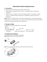
Chapter 1: Introducing the SolarEdge Power
Harvesting System
TheSolarEdgepowerharvestingsolutionisdesignedtomaximizethepoweroutputfromanytypeof
solarPhotovoltaic(PV)installationwhilereducingtheaveragecostperwatt.Thefollowingsections
describeeachofthesystem’scomponents.
Figure 1: The SolarEdge power harvesting system components
Power Optimiser
ThepoweroptimisersareDC-DCconvertersconnectedtoPVmodulesinordertomaximizepower
harvestingbyperformingindependentMaximumPowerPointTracking(MPPT)atthemodulelevel.
Thepoweroptimisersregulatethestringvoltageataconstantlevel,regardlessofstringlengthand
environmentalconditions.
Thepoweroptimisersincludeasafetyvoltagefunctionthatautomaticallyreducestheoutputofeach
poweroptimiserto1Vdcinthefollowingcases:
lDuringfaultconditions
lThepoweroptimisersaredisconnectedfromtheinverter
lTheinverterON/OFFswitchisturnedOFF
lThesafetyswitchontheConnectionUnitisturnedOFF
lTheinverterACbreakeristurnedOFF
lTheRapidShutdown(PVRSS)isinitiatedbyoneofthefollowingmethods:
oInverterACbreakeristurnedOFF,orACtotheinverterisdisconnectedbyanothermethod
(intentionallyorasresultofafault)
oInverterON/OFFswitchisturnedOFF
oTheConnectionUnitisturnedOFF
EachpoweroptimiseralsotransmitsmoduleperformancedataovertheDCpowerlinetotheinverter.
Twotypesofpoweroptimisersareavailable:
lModuleAdd-onpoweroptimiser–connectedtooneormoremodules
lSmartmodules-thepoweroptimiserisembeddedintoamodule
-Three Phase Inverter with Synergy Technology Installation MAN-01-00402-1.4
10
Chapter 1: Introducing the SolarEdge Power Harvesting System

Three Phase Inverter with Synergy Technology
TheThreePhaseInverterwithsynergytechnologyinverter(referredtoas'inverter'inthismanual)
efficientlyconvertsDCpowerfromthemodulesintoACpowerthatcanbefedintothemainACservice
ofthesiteandfromtheretothegrid.Theinverteralsoreceivesthemonitoringdatafromeachpower
optimiserandtransmitsittotheSolarEdgemonitoringplatform(requiresInternetorCellular
connection).
TheinverteriscomprisedofonePrimaryUnitwithanintegratedConnectionUnitwithaDCSafety
Switch(referredtoas'ConnectionUnit'inthismanual)fordisconnectingtheDCpowerofaSolarEdge
system,andofoneortwoSecondaryUnits,dependingontheinverter'scapacity.TheSecondaryUnit(s)
areconnectedtotheprimaryunitwithAC,DCandcommunicationcables.
Eachunitoperatesindependentlyandcontinuestoworkincasetheothersarenotoperating.
Youcansetupamaster-slaveconfiguration,connectingupto31additionalinverterstoonemaster
inverter.
Figure 2: Primary Unit with two Secondary Units
Chapter 1: Introducing the SolarEdge Power Harvesting System
-Three Phase Inverter with Synergy Technology Installation MAN-01-00402-1.4
11

Monitoring Platform
Themonitoringplatformenablesmonitoringthetechnicalandfinancialperformanceofoneormore
SolarEdgesites.Itprovidespastandpresentinformationonthesystemperformancebothatthesystem
andmodulelevels.
Supported ACGrids
ThefollowingsectionshowstheACgridssupportedbytheinverters(modeldependent).
Groundconnectionisrequiredforallgrids,asdescribedinConnectingtheACGridandGroundingtothe
ConnectionUnitonpage37.
Figure 3: AC grids supported by SolarEdge three-phase inverters
NOTE
Somethreephaseinverterssupportthe208VDeltagrid.RefertoSettingtheInverterto
Support208V3-wireGridonpage41.
Installation Procedure
ThefollowingistheprocedureforinstallingandsettingupanewSolarEdgesite.Manyofthesealsoapply
tomodificationofanexistingsite.
1. InstallingthePoweroptimisers,page14
2. MountingandConnectingthePrimaryandSecondaryUnit(s),page29
NOTE
It is recommended to connect communication connections (step 6 of this installation) before
connecting the AC, for easier access to the communication board.
3. ConnectingtheACandtheStringstotheConnectionUnit,37
4. ActivatingandCommissioningtheSystemUsingSetApp,page42
5. ConfiguringtheSystemUsingSetApp,page44
6. SettingUpCommunicationpage57
-Three Phase Inverter with Synergy Technology Installation MAN-01-00402-1.4
12
Monitoring Platform

Installation Equipment List
StandardtoolscanbeusedduringtheinstallationoftheSolarEdgesystem.Thefollowingisa
recommendationoftheequipmentneededforinstallation:
lAllenscrewdriverfor5mmscrewtypefortheinvertercover,ConnectionUnitcover,andinverterside
screws
l17/32HEXAllenscrewdriverforACstudconnector
lSolarEdgesuppliedlevel
lSolarEdgesuppliedDC/interlockconduit(s)
lStandardflat-headscrewdriversset
lNon-contactvoltagedetector
lCordlessdrill(withatorqueclutch)orscrewdriverandbitssuitableforthesurfaceonwhichthe
inverterandoptimiserswillbeinstalledandforopeningtheConnectionUnitdrillguides.Useofan
impactdriverisnotallowed.
lAppropriatemountinghardware(forexample:stainlessbolts,nuts,andwashers)forattaching:
othePrimaryandSecondaryUnit(s)mountingbracketstothemountingsurface
othepoweroptimiserstotheracking(notrequiredforsmartmodules)
l4xM8ringterminalsandsuitablecrimper
lWirecutters
lWirestrippers
lVoltmeter
Forinstallingthecommunicationoptions,youmayalsoneedthefollowing:
lForEthernet:
oCAT5/6twistedpairEthernetcablewithRJ45connector
oIfusingaCAT5/6cablespool:RJ45plugandRJ45crimper
lForRS485:
oFour-orsix-wireshieldedtwistedpaircable.
oWatchmakerprecisionscrewdriverset
Chapter 1: Introducing the SolarEdge Power Harvesting System
-Three Phase Inverter with Synergy Technology Installation MAN-01-00402-1.4
13

Chapter 2: Installing the Power Optimisers
Safety
ThefollowingnotesandwarningsapplywheninstallingtheSolarEdgepoweroptimisers.Someofthe
followingmaynotbeapplicabletosmartmodules:
WARNING!
The metallic enclosure of the power optimiser must be grounded in accordance with the product's listing
and local and national codes.
L'enceinte métallique de l’optimiseur de puissance doit être mise à la terre en accord avec les
régulations locales et nationales.
WARNING!
When modifying an existing installation, turn OFF the inverter ON/OFF switch, the Connection Unit and
the AC circuit breaker on the main AC distribution panel.
Avant de faire ces étapes, éteignez l'onduleur monophasé en mettant sur OFF l'interrupteur ON/OFF
situé au bas de l'onduleur.
CAUTION!
Power optimisers are IP68/NEMA6P rated. Choose a mounting location where optimisers will not be
submerged in water.
Les optimiseurs de puissances sont compatibles à la norme IP68/NEMA6P. Choisissez le lieu de
montage tel que l’optimiseur ne puisse pas être submergé par l’eau.
CAUTION!
This unit must be operated according to the operating specifications provided with the unit.
Cette unité doit être opérée suivant les instructions trouvées dans le manuel fourni avec le produit.
CAUTION!
Cutting the power optimiser input or output cable connector is prohibited and will void the warranty.
Sectionner les cables d’entrées ou de sortie de l’optimiseur est interdit et annule sa garantie.
CAUTION!
All PV modules must be connected to a power optimiser.
Tous les modules doivent être connectés à un optimiseur de puissance.
CAUTION!
If you intend to mount the optimisers directly to the module or module frame, first consult the module
manufacturer for guidance regarding the mounting location and the impact, if any, on module warranty.
Drilling holes in the module frame should be done according to the module manufacturer instructions.
Pour installation à même le module ou la monture du module, consultez d'abord le fabricant du module
sur la position et son impact sur la garantie du module. Le perçage de trous dans le cadre du module
devra se faire suivant les instructions du fabricant.
IMPORTANT SAFETY FEATURE
Modules with SolarEdge power optimisers are safe. They carry only a low safety voltage before the
inverter is turned ON. As long as the power optimisers are not connected to the inverter or the inverter is
turned OFF, each power optimiser will output a safe voltage of 1V.
-Three Phase Inverter with Synergy Technology Installation MAN-01-00402-1.4
14
Chapter 2: Installing the Power Optimisers

CAUTION!
Installing a SolarEdge system without ensuring compatibility of the module connectors with the
optimiser connectors may be unsafe and could cause functionality problems such as ground faults,
resulting in inverter shut down. To ensure mechanical compatibility of the SolarEdge optimisers’
connectors with the PV modules’ connectors to which they are connected:
lUse identical connectors from the same manufacturer and of the same type on both the power
optimisers and on the modules; or
lVerify that the connectors are compatible in the following way:
oThe module connector manufacturer should explicitly verify compatibility with the SolarEdge
optimiser connector; and
oA third-party test report by one of the listed external labs (TUV, VDE, Bureau Veritas UL, CSA,
InterTek) should be obtained, verifying the compatibility of the connectors.
ATTENTION!
Les connecteurs du module doivent être mécaniquement compatibles avec les optimiseurs de
puissance. Sinon, le système SolarEdge installé peut être dangereux ou causer des problèmes
fonctionnels, tels que les défauts de terre, qui peuvent provoquer un arrêt de l’onduleur. Afin d'assurer la
compatibilité mécanique entre les optimiseurs de puissance SolarEdge et les modules auxquels ils sont
connectés:.
lUtiliser des connecteurs identiques du même fabricant et du même type aussi bien pour les
optimiseurs de puissance que pour les modules.
lVérifiez que les connecteurs sont compatibles de la manière suivante:
oLe fabricant du connecteur doit explicitement vérifier la compatibilité avec le connecteur
SolarEdge.
oUn rapport de test de tierce partie doit être effectué par l’un des laboratoires externes indiqués ci-
dessous:(TUV, VDE, Bureau Veritas UL, CSA,Intertek), qui vérifiera la compatibilité des
connecteurs.
Package Contents
lPoweroptimisers
lStainlesssteelgroundinglockwashers
Installation Guidelines
lFrame-mountedpoweroptimisersaremounteddirectlyonthemoduleframe,
regardlessofrackingsystem(rail-lessorwithrails).Forinstallationofframe-mounted
poweroptimisers,refertohttp://www.solaredge.com/sites/default/files/installing_
frame_mounted_power_optimizers.pdf.
lThestepsinthischapterrefertomoduleadd-onpoweroptimisers.Forsmart
modules,startfromStep3:ConnectingPowerOptimisersinStringsonpage19.Also
refertothedocumentationsuppliedwiththesmartmodules.
lThepoweroptimisercanbeplacedinanyorientation.
lIfconnectingmoremodulesthanoptimiserinputsinparallel,useabranchcable.Somecommercial
poweroptimisermodelshaveadualinput.
lPositionthepoweroptimisercloseenoughtoitsmodulesothattheircablescanbeconnected.
lMakesuretousepoweroptimisersthathavetherequiredoutputconductorlength:
Chapter 2: Installing the Power Optimisers
-Three Phase Inverter with Synergy Technology Installation MAN-01-00402-1.4
15

oDonotuseextensioncablesbetweenamoduleandapoweroptimiser,betweentwomodules
connectedtothesameoptimiser,orbetweentwooptimisersotherthaninthecasesspecified
below.
oYoucanuseextensioncablesbetweenpoweroptimisersonlyfromrowtorow,aroundobstacles
withinarow,andfromtheendofthestringtotheinverter,aslongasthemaximumdistanceis
notexceeded.
lTheminimumandmaximumstringlengthguidelinesarestatedinthepoweroptimiserdatasheets.
RefertotheDesignerforstringlengthverification.TheDesignerisavailableontheSolarEdgewebsite
athttps://www.solaredge.com/us/products/installer-tools/designer#/.
lCompletelyshadedmodulesmaycausetheirpoweroptimiserstotemporarilyshutdown.Thiswill
notaffecttheperformanceoftheotherpoweroptimisersinthestring,aslongastheminimum
numberofunshadedpoweroptimisersconnectedinastringofmodulesismet.Ifundertypical
conditionsfewerthantheminimumoptimisersareconnectedtounshadedmodules,addmore
optimiserstothestring.
lEquipmentgroundingtighteningtorques:4-6AWG:45lb-in,8AWG:40lb-in,10-14AWG:35lb-in.
lToallowforheatdissipation,maintaina2.5cm/1"clearancedistancebetweenthepoweroptimiser
andothersurfaces,onallsidesexceptthemountingbracketside.
Figure 4: Power optimiser clearance
lWheninstallingmodulesinaconfinedspace,forexample,ifinstallingBuilding-integratedphotovoltaic
(BIPV)modules,ventilationmeasuresmaybeneededtoensurethepoweroptimisersarenotbe
exposedtotemperaturesoutsidetheirspecifications.
NOTE
The images contained herein are for illustrative purposes only and may vary depending on product
models.
Step 1: Mounting and Grounding the Power
Optimizers
Foreachofthepoweroptimisers1:
1Not applicable to smart modules.
-Three Phase Inverter with Synergy Technology Installation MAN-01-00402-1.4
16
Step 1: Mounting and Grounding the Power Optimizers

1. Determinethepoweroptimisermountinglocationandusethepoweroptimiser
mountingbracketstoattachthepoweroptimisertothesupportstructure(See
Figure5).Itisrecommendedtomountthepoweroptimiserinalocationprotected
fromdirectsunlight.Forframe-mountedpoweroptimisersfollowtheinstructions
suppliedwiththeoptimisers,orreferto
https://www.solaredge.com/sites/default/files/installing_frame_mounted_power_
optimizers.pdf.
2. Ifrequired,markthemountingholelocationsanddrillthehole.
CAUTION!
Drilling vibrations may damage the power optimiser and will void the warranty. Use a torque wrench
or an electric drill with adjustable clutch that meets the mounting torque requirements. Do not use
impact drivers for mounting the power optimiser.
Do not drill through the power optimiser or through the mounting holes.
ATTENTION!
Les vibrations résultant du perçage peuvent endommager l’optimiseur de puissance et annulera la
garantie. Utilisez une clé dynamométrique ou une perceuse électrique avec embrayage adaptable
compatible avec les moments indiqués. Ne pas utiliser des tournevis à percussion pour fixer
l’optimiseur. Ne pas percer à travers l’optimiseur de puissance ou ses trous de fixation.
3. AttacheachpoweroptimisertotherackusingM6(1/4'')stainlesssteelbolts,nutsandwashersor
otherappropriatemountinghardware.Applytorqueof9-10N*m/6.5-7lb*ft.
For3NAseriespoweroptimizes,SolarEdgerecommendsmountingthepoweroptimiseronarailwith
thesmoothsidefacingout,sothatthepoweroptimiserbodywillpreventitsrotation.
4. Usethefollowingmethods1togroundthepoweroptimizer:
WARNING!
The metallic enclosure of the power optimiser must be grounded in accordance with the
requirements of the local and national codes.
AVERTISSEMENT!
L'enceinte métallique de l’optimiseur de puissance doit être mise à la terre en accord avec les
régulations locales et nationales.
lFor mounting on a grounded metal rail:Usetheprovided5/16''stainlesssteelgroundingstar
washerbetweentherailingandtheflatsideofthemountingbracket.Thegroundingwasher
shouldbreakthroughtheanodizecoatingoftherailingtoensurelowresistiveconnection.Apply
torqueof9.5N*m/7lb*ft.SeeFigure5.
1These methods have been evaluated by a nationally recognized testing laboratory as part of the optimiser evaluation.
The SolarEdge-supplied grounding lug kit has been evaluated only for use with SolarEdge power optimizers. It is not
intended or listed to be used as a general purpose grounding lug with other electrical equipment.
Chapter 2: Installing the Power Optimisers
-Three Phase Inverter with Synergy Technology Installation MAN-01-00402-1.4
17

Figure 5: Power optimiser installation and grounding using a star washer
lFor mounting on rails with sliding nut fasteners:Ifthestarwashercannotbeused,usethe
SolarEdgegroundingplate(purchasedseparately)betweentherailingandtheflatsideofthe
mountingbracket.Usemountingspecifichardwareasneeded.Applytorqueof9.5N*m/7lb*ft.
SeeFigure6
Figure 6: Power optimiser installation and grounding using a grounding plate
lFor mounting on un-grounded structures(suchasawoodenstructure):Ifthestarwasheror
theplatecannotbeused,usetheSolarEdgegroundinglug(purchasedseparately)withan
equipment-groundingconductoraccordingtothesuppliedinstructions.Thegroundingterminal
acceptsawiresizeof6-14AWG,andmustbesizedforequipmentgroundingperNEC250.122
requirements.Tightenthescrewsconnectingthepoweroptimisertotheframeandthe
groundingterminalscrew.Applytorqueof9.5N*m/7lb*ft.SeeFigure7
Figure 7: Power optimiser grounding terminal
5. Verifythateachpoweroptimiserissecurelyattachedtothemodulesupportstructure.
-Three Phase Inverter with Synergy Technology Installation MAN-01-00402-1.4
18
Step 1: Mounting and Grounding the Power Optimizers

6. Recordpoweroptimiserserialnumbersandlocations,asdescribedinReportingandMonitoring
InstallationDataonpage54.
Step 2: Connecting a PV Module to a Power
Optimiser
NOTE
Images are for illustration purposes only. Refer to the label on the product to identify the plus and
minus input and output connectors.
Foreachofthepoweroptimisers:
lConnectthePlus(+)outputconnectorofthemoduletothePlus(+)inputconnectorofthepower
optimiser.
lConnecttheMinus(-)outputconnectorofthemoduletotheMinus(-)inputconnectorofthe
poweroptimiser.
Figure 8: Power optimiser connectors
Step 3: Connecting Power Optimisers in Strings
Youcanconstructparallelstringsofunequallength,thatis,thenumberofpoweroptimisersineach
stringdoesnothavetobethesame.Theminimumandmaximumstringlengthsarespecifiedinthe
powerdatasheets.RefertotheSolarEdgeSiteDesignerforstringlengthverification.
NOTE
lUse at least 11 AWG/ 4 mm² DC cables.
lThe total conductor length of the string (excluding power optimisers’ conductors; including home
runs and necessary extensions between optimisers) should not exceed:
IMPORTANT SAFETY FEATURE
lFor a compliant PV Rapid Shutdown (PVRSS) installation, use no more than 30 optimisers per
string.
lEnabling PVRSS from the inverter menu is only required if the installed optimisers were
manufactured before 2015, otherwise it is enabled by default.
NOTE
The DC bus of each unit is separate and not shared for all units. Therefore in addition to following the
inverter design rules, each unit should follow the unit design rules as detailed in the Technical
Specifications.
Chapter 2: Installing the Power Optimisers
-Three Phase Inverter with Synergy Technology Installation MAN-01-00402-1.4
19
/