Page is loading ...

9
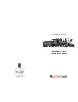
D51 200 Steam Locomotive: STEP BY STEP ™
Spark arrester and
blast pipe
Spark arrester lip
Spark arrester mesh (ared)
Spark arrester ring
Spark arrester mesh (cylindrical)
Spark arrester base
Blast pipe
2 × 4mm screws × 5
Before assembling
the spark arrester, you
need to identify the
dierences between
the two sides of the
ring. On one side, the
outer edge is thin and
on the other side it is
much thicker. The ring
ts onto the narrow
end of the ared mesh.
Test-t the ring in place
on the narrow end of
the ared mesh to more
easily identify the correct
orientation of the ring.
Required tools
Tweezers
Phillips screwdriver
Instant adhesive
Your parts
Checking the parts
1
Spark arrester and blast pipe
Thin
(upper side)
Thick
(lower side)
Correct orientation (thick side up)
Incorrect orientation (thin side up)
Stage 5

10
D51 200 Steam Locomotive: STEP BY STEP ™
Apply instant adhesive to the
groove on the upper side of
the spark arrester ring.
Apply adhesive to the inside of the
ring at the wide end of the ared
mesh, and place the lip inside the
ring, as shown.
Fit the ring at the narrow end
of the ared mesh. If the bond
between the two is weak, apply
more adhesive to the join.
Apply some instant adhesive
to the inside edge of the base
(red line), as shown.
Apply adhesive to the lower side of the ring and
x the open side of the cylindrical mesh into it.
Before the glue dries, adjust the positions of the
parts so that the weld lines are aligned (circled).
When the spark arrester is glued
in place, turn the smokebox
assembly around to drop the
blast pipe into place. Hold
the blast pipe in position and
turn the smokebox over again.
Align the four holes of the
blast pipe with those on the
underside of the smokebox
(circled) and tighten a screw
into each.
As shown in the photo, place
the blast pipe into the base of
the spark arrester. Though they
are not glued together, this is
necessary to be able to secure
the blast pipe in place.
Fit the spark arrester assembly over the
underside of the chimney, positioning the lip
over the bottom of the chimney and slotting
the assembly into place.
Assembling the spark arrester
2
Fitting the blast pipe
4
Fitting the spark arrester
3
Completed parts
Position the smokebox assembly
upside down. Apply adhesive to
the lip on the underside of the
chimney. You may prefer to use
epoxy adhesive.
If you can't keep the smokebox held
upside down, you will need to hold
the spark arrester in place while the
adhesive dries. Be careful not to press
too hard as this may warp the mesh.

11
D51 200 Steam Locomotive: STEP BY STEP ™
Front deck
Front deck edges × 2
Front deck
Front deck base
Place the front deck onto the base,
to check the positioning.
Coat the back of the front deck with
contact adhesive.
To help you hold
the two front deck
parts together,
you may want to
use the left-over
screws from Stages
2 and 5.
Place the front deck
onto the base, and
secure it in place with
the screws.
Required tools
Clamps x 3
Instant adhesive
Contact adhesive
Phillips screwdriver
You may also want to use:
The two screws left over from
Stages 2 and 5
Your parts
The screws will be
removed when the glue
has dried, but they are
used here to keep the
two parts aligned.
Assembling the front deck
1
Front deck
Stage 6

12
D51 200 Steam Locomotive: STEP BY STEP ™
Clamp the area next to the screws, as
shown above. Make sure that there are no gaps in
the seam between the two parts of the
front deck.
Clamp the left and right sides of the deck
as well.
Place the edge piece along the
seam and hold in position until the
adhesive has dried.
Fitting the front deck
2Positioning the front deck
3
Fitting the edges
4
Completed parts
Apply instant adhesive along the seam
between the two parts of the front deck, at
the side.
Glue the second
edge piece to
the other side.
When dry, apply
some more
glue, as shown,
to increase the
strength of
the bond.
Keep the assembly held in the clamps
until the adhesive is dry. When dry,
remove the clamps and the screws.
Hold the front deck and one of the edge
parts, as shown, and test-t together, with
the edge behind the deck top.

13
D51 200 Steam Locomotive: STEP BY STEP ™
Maintenance hatch and
lamp hooks
Maintenance hatch
Maintenance hatch upper surface
Maintenance hatch front cover
Lamp hooks × 2
Place the maintenance hatch onto
the front deck, in the central area.
Place the front deck, assembled in Stage 6, as
shown, and hold the maintenance hatch above it.
Apply instant adhesive to
the inner seam between
the two parts.
Required Tools
Tweezers
Instant adhesive
Contact adhesive
Your parts
Fitting the maintenance hatch
1
Maintenance hatch and lamps hooks
Stage 7

14
D51 200 Steam Locomotive: STEP BY STEP ™
Hold one of the hooks with
tweezers, as shown in the
photo on the left, and place
it into the hole on the front
of the hatch.
Holding the hook in
place, apply a small
amount of instant
adhesive to the hole from
the inside of the hatch.
Repeat this process for
the second hook.
Before the adhesive dries,
adjust the positions of the
hooks so that they appear
at right angles, as in the
above photo.
Place the hatch upper surface on
top of the hatch.
As highlighted in the inset, the upper
surface will overlap the sides slightly.
Turn the assembly over, holding the
upper surface in place.
Apply instant adhesive to the
seam between the assembly
and the upper surface.
Hold the front cover with the
projections facing away from you.
Then apply instant adhesive to the
back of the front cover.
Place the front cover on the front of
the hatch, between the hooks.
Check that you have the front
cover in the correct orientation,
with the hinges slightly below
the middle, as in the photo.
Lamp hook mounting
2
The hatch upper surface
4
Installing the front cover
3
Completed parts
Hinges

15
D51 200 Steam Locomotive: STEP BY STEP ™
Release lever, front-end
beam and guard irons
Lay out the release
lever parts A
and B, as shown,
to identify the
dierent directions
of the twist
(circled).
Test-t all of the release
lever parts A and B on the
release lever bar.
Required Tools
Phillips screwdriver
Instant adhesive
Contact adhesive
Epoxy adhesive
Your parts
B
A
Position the release
lever parts on the
bar, as shown in the
photo. Make sure
the projections on
the parts A and B are
pointing down, with
the hooked ends of
the bar facing
towards you.
Assembling the release lever
1
Release lever, front-end beam and
guard irons
Release lever bar
Release levers A × 2
Release levers B × 2
Right guard iron
Left guard iron
2 × 4mm screws × 5
Front-end beam
A AB B
Stage 8

16
D51 200 Steam Locomotive: STEP BY STEP ™
Hold the release lever
bar over the front-
end beam, lining
up the parts A and
B with the pairs of
holes (circled). Push
the glued projections
into the holes, using
the assembled parts
photo for reference.
When all the
projections are
tted into their
corresponding
holes, turn the
assembly over and
apply glue to the
backs of the holes
to secure.
Position the guard irons as
shown, to identify the dierence
between the two pieces.
Apply a small amount of
adhesive to the tops of the
guard irons and screw into
place on the underside of the
front-end beam (circled).
Apply epoxy adhesive to the highlighted
area (red lines) of the front deck.
Place the front-end beam on this area,
aligning the holes (circled).
Apply a small amount of
contact adhesive or epoxy
to the two projections on
the release lever parts (A
and B).
Installing the release lever
2
Fitting the guard irons
4
Installing the front-end beam
3
Assembled parts
Fix a screw into each of the
two aligned holes (circled)
to secure the front-end
beam to the front deck.
Right
Right
Left
Left
Angled side
/