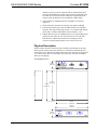
Crestron ST-COM is a powerful and versatile device that allows you to control a wide range of serial devices using your Crestron control system. With its two independent bidirectional serial ports, you can connect to and control devices such as video projectors, AV switchers, and more. The ST-COM supports a variety of communications parameters, including baud rate, parity, data bits, stop bits, and handshaking. It can be used as part of a Cresnet system, allowing you to power the device over the network and daisy-chain multiple units together. The ST-COM also features a variety of built-in protections, including overvoltage and electrostatic discharge protection. Whether you're looking to add control for additional serial devices to your home or business, the Crestron ST-COM is the perfect solution. Here are just a few of the possible use cases for the ST-COM:
Crestron ST-COM is a powerful and versatile device that allows you to control a wide range of serial devices using your Crestron control system. With its two independent bidirectional serial ports, you can connect to and control devices such as video projectors, AV switchers, and more. The ST-COM supports a variety of communications parameters, including baud rate, parity, data bits, stop bits, and handshaking. It can be used as part of a Cresnet system, allowing you to power the device over the network and daisy-chain multiple units together. The ST-COM also features a variety of built-in protections, including overvoltage and electrostatic discharge protection. Whether you're looking to add control for additional serial devices to your home or business, the Crestron ST-COM is the perfect solution. Here are just a few of the possible use cases for the ST-COM:


-
 1
1
-
 2
2
-
 3
3
-
 4
4
-
 5
5
-
 6
6
-
 7
7
-
 8
8
-
 9
9
-
 10
10
-
 11
11
-
 12
12
-
 13
13
-
 14
14
-
 15
15
-
 16
16
-
 17
17
-
 18
18
-
 19
19
-
 20
20
-
 21
21
-
 22
22
-
 23
23
-
 24
24


Crestron ST-COM is a powerful and versatile device that allows you to control a wide range of serial devices using your Crestron control system. With its two independent bidirectional serial ports, you can connect to and control devices such as video projectors, AV switchers, and more. The ST-COM supports a variety of communications parameters, including baud rate, parity, data bits, stop bits, and handshaking. It can be used as part of a Cresnet system, allowing you to power the device over the network and daisy-chain multiple units together. The ST-COM also features a variety of built-in protections, including overvoltage and electrostatic discharge protection. Whether you're looking to add control for additional serial devices to your home or business, the Crestron ST-COM is the perfect solution. Here are just a few of the possible use cases for the ST-COM:
Ask a question and I''ll find the answer in the document
Finding information in a document is now easier with AI
Related papers
-
Crestron ST-CNB User manual
-
-
-
-
-
-
-
-
-


