Page is loading ...

12” Deluxe Woodworking Bandsaw
Model: 10-315
Owner’s Manual
For more information:
www.rikontools.com or [email protected]
For Parts or Questions:
[email protected] or 877-884-5167
Record the serial number and date of purchase
in your manual for future reference.
Serial number:
Date of purchase:
Part #10-315M1

IMPORTANT! Safety is the single most important consideration in the operation of this equipment. The following
instructions must be followed at all times.
There are certain applications for which this tool was designed. We strongly recommend that this tool not be modied and/
or used for any other application other than that for which it was designed. If you have any questions about its application,
do not use the tool until you have contacted us and we have advised you.
General Safety Warnings
KNOW YOUR POWER TOOL. Read the owner’s manual carefully. Learn the tool’s applications, work
capabilities, and its specic potential hazards.
ALWAYS KEEP VISITORS AWAY FROM RUNNING MACHINES.
All visitors should be kept a safe distance from the work area.
ALWAYS MAKE THE WORKSHOP CHILDPROOF.
Childproof with padlocks, master switches, or by removing starter keys.
NEVER OPERATE A TOOL WHILE UNDER THE INFLUENCE OF DRUGS,
MEDICATION, OR ALCOHOL.
ALWAYS WEAR PROPER APPAREL.
Never wear loose clothing or jewelry that might get caught in moving parts. Rubber-soled footwear is
recommended for the best footing.
ALWAYS USE SAFETY GLASSES AND WEAR HEARING PROTECTION.
Also use a face or dust mask if the cutting operation is dusty.
NEVER OVERREACH.
Keep your proper footing and balance at all times.
ALWAYS GROUND ALL TOOLS.
If your tool is equipped with a three-pronged plug, you must plug it into a three-hole electric receptacle.
If you use an adapter to accommodate a two-pronged receptacle, you must attach the adapter plug to a
known ground. Never remove the third prong of the plug.
ALWAYS AVOID DANGEROUS ENVIRONMENTS.
Never use power tools in damp or wet locations. Keep your work area well lighted and clear of clutter.
ALWAYS REMOVE THE ADJUSTING KEYS AND WRENCHES FROM TOOLS AFTER USE.
Form the habit of checking to see that keys and adjusting wrenches are removed from the tool before
turning it on.
ALWAYS KEEP YOUR WORK AREA CLEAN. Cluttered areas and benches invite accidents.
NEVER STAND ON TOOLS.
Serious injury could occur if the tool is tipped or if the cutting tool is accidentally contacted.
2
Operator Safety: Required Reading

ALWAYS CHECK FOR DAMAGED PARTS.
Before initial or continual use of the tool, a guard or other part that is damaged should be checked to
assure that it will operate properly and perform its intended function. Check for alignment of moving
parts, binding of moving parts, breakage of parts, mounting, and any other conditions that may affect its
operation. A guard or other damaged parts should immediately be properly repaired or replaced.
ALWAYS DISCONNECT TOOLS.
Disconnect tools before servicing and when changing accessories such as blades, bits, and cutters.
ALWAYS AVOID ACCIDENTAL STARTING.
Make sure switch is in “OFF” position before plugging in cord.
NEVER LEAVE TOOLS RUNNING UNATTENDED.
1. Always allow the Bandaw blade to stop before removing scrap pieces from table.
2. Always keep hands and ngers away from the blade.
3. Never attempt to saw stock that does not have a at surface, unless a suitable support is used.
4. Always hold material rmly and feed it into the blade at a moderate speed.
5. Always turn off the machine if the material is to be backed out of an uncompleted cut.
6. Adjust the upper guide about 1/8” above the material being cut.
7. Check for proper blade size and type for thickness and material being cut.
8. Make sure that the blade tension and blade tracking are properly adjusted.
9. Make “relief” cuts before cutting long curves.
10. Release blade tension when the saw will not be used for a long period of time.
Special Safety Rules For Bandsaws
SAVE THESE INSTRUCTIONS.
Refer to them often.
3
California Propsition 65 Warning
WARNING: Some dust created by power sanding, sawing, grinding, drilling, and other construction
activities contains chemicals known to the State of California to cause cancer and birth defects or
other reproductive harm. Your risk from exposure to these chemicals varies, depending on how often
you do this type of work. To reduce your exposure, work in a well-ventilated area and with approved
safety equipment, such as dust masks that are specially designed to lter out microscopic particles.
For more detailed information about California Propostion 65 log onto rikontools.com.

Safety Warnings..................................................................................................................................2 -3
Bandsaw Safety Rules ..........................................................................................................................3
Specications ........................................................................................................................................4
Contents of Package ............................................................................................................................5-6
Getting To Know Your Bandsaw ............................................................................................................7
Stand Assembly ..............................................................................................................................................8
Assembly ..............................................................................................................................................9
Assembly the Working Table.........................................................................................................................9
Rip Fence Assembly .............................................................................................................................9
Installing the Tool Holder.......................................................................................................................................10
Hand-Wheel Assembly .........................................................................................................................10
Setting the Table Square to the Blade................................................................................................................10
Tilting the Table .....................................................................................................................................11
Tracking the Saw Blade ......................................................................................................................................11
Adjusting Blade Tension .......................................................................................................................11
Upper Blade Guide Adjustment .....................................................................................................................11-12
Lower Blade Guide Adjustment ..........................................................................................................................12
Adjusting the Rip Fence/Drift................................................................................................................................12-13
Rip Fence Scale Adjustment ...............................................................................................................13
Cutting Height Adjustment ..................................................................................................................13
Changing Blade Speed/Belt Tension..............................................................................................................14
Replacing Blades ................................................................................................................................14-15
Resawing .............................................................................................................................15
Operation ............................................................................................................................................15
Maintenance .......................................................................................................................................... ..... 16
Wiring Diagram ...................................................................................................................................16
Troubleshooting .........................................................................................................................17-18
Changing Bandsaw Tire ...................................................................................................................................18
Parts Diagram ................................................................................................................................19-21
Parts List ........................................................................................................................................22-23
How To Guide .....................................................................................................................................24
Warranty .............................................................................................................................................25
Notes......................................................................................................................................26-27
4
12”
7”
93-1/2”
1/8” – 3/4”
18-7/8””x 15-3/4”
Left-10
o
Right-45
o
1496 ft/min or 3230 ft/min
1 HP
10/5
110/220
176 lbs
Throat width
Max. cutting depth
Blade length
Blade width
Table size
Table tilt
Blade speeds
Motor
Amps
Volts
Net weight
Specications
Table of Contents

5
Model 10-315 12” Deluxe Woodworking Bandsaw is shipped complete in one box.
1. Unpacking and Checking Contents
a. Separate all “loose parts” from packaging materials, the following components are included
for the initial assemble and make sure all items are accounted for, before discarding any
packaging material.
b. With the help of another person, take the Bandsaw from the packing carton. Properly lift the
Bandsaw off the packing carton and place on level oor.
c. Remove protective oil that is applied to the table. Use any ordinary house hold type grease or
spot remover.
d. Apply a coat of paste wax to the table to prevent rust. Wipe all parts thoroughly with a clean
dry cloth.
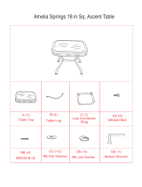
Contents of Package
A
B
C
D
E
A. Bandsaw Body
B. Cabinet Stand Box
C. Crank Handwheel
D. Blade Tension Wheel
E. Manual

6
Contents of Package Cont.
Table assembly:
A. Table
B. Table leveling bar and hardware
C. 90° table stop bolt
D. Table mounting bolts and washers
Rip fence assembly:
A. Scale
B. Fence bar
C. Fence
D. Resaw bar
E. Fence carrier
F. Fence support on left side of the table
G.Lock shoe
A
B
C
D
E
E
F
D
C
B
F
A
G
Tool holder assembly:
A. L wrench 3MM
B. L wrench 4MM
C. L wrench 5MM
D. L wrench 6MM
E. Tool holder
F. Tool Holder mounting screws
A B
C
D

7
Getting to Know Your Bandsaw
A Blade Tensioning Knob
B Rise & Fall Hand Wheel
C Blade
D Upper Blade Guide
E Table
F Rip Fence
G Rip Fence Rail
H Table Tilt Lock Handle
I Stand (Model#10-315 doesn’t include wheel kit)
J Belt Tension & Speed Change Handle
K Blade Tension Release Cam Handle
L Rise & Fall Lock Knob
M Blade Tracking Knob
N Table Tilting Knob
P 4” Dust Extraction Port
Q Motor
A
B
C
F
I
D
E
H
J
L
P
K
M
Q
N
G

8
Caution: To avoid back injury, get help lifting the bandsaw. Bend your knees, lift with your legs, not
your back.
Stand Assembly
Note: When assembling this
legstand do not fully tighten
the nuts and bolts until the
assembly is complete.
1. Locate the first leg and
secure it to one of the long top
brace supports using the nuts,
bolts and washers supplied
Fig.1S.
2. In the same way, attach the
second leg to the brace support
Fig.2S.
3. Locate the short top brace
supports and install to the legs
as shown Fig.3.S.
4. Continue in this way until
all of the legs and top brace
supports have been installed
Fig.4S.
5. Holes a third of the way down
each leg are for securing the
mid brace supports. Attach the
long mid brace supports to the
frame using the nuts, bolts and
washers Fig.5S.
6. Finally, install the short mid
brace support to one of the
shorter sides Fig.6S.
Note
The side with the short mid
brace support installed will
referred to as the front of the
stand. This leaves the back
area free for the optional wheel
kit operation.
Fig.4.S
Fig.1S
Fig.6S
FRONT
LONG TOP BRACE
SUPPORT
SHORT TOP BRACE
SUPPORTS
Fig.5S
LONG MID BRACE
SUPPORT
Fig.2S
Fig.3.S

Mounting Top to Stand
Feed the long mounting bolts up through the stand
and secure the four corners using the washers and
bolts provided (A-Fig.1). Lift the bandsaw over the
stand and place the long mounting bolts through the
four location holes in the bandsaw base.
Assemble Working Table
Installing 90°stop: Thread screw (M8x25) and nut
(M8) to the bottom of the table. (A-Fig.2) With
the help of another person, lift the working table
onto the trunnion. Mount the working table to the
trunnion using the supplied (4) hex bolts, (4) lock
washers and (4) washers (B-Fig.2). Install the two
bolts to the right of the blade hand tight, then tip the
table to 45 degrees and install the two bolts to the
left of the blade. Adjust table parallel to blade and
tighten bolts.
Table Leveling Bar: The table leveling bar is
preinstalled from the factory and must be removed
before installing the table. The table leveling bar
keeps the two sides of the blade slot level.
(C-Fig. 2)
Fence Support Bolt: Install the fence support bolt in
the left rear corner of the table. (D-Fig. 2)
Figure 1
Figure 4
9
A
B
Figure 2
Figure 3
Assembly
Rip Fence Assembly
Mount the fence bar onto the table with the two
fence bar nuts.(A-Fig 3) Do not fully tighten yet as
they may need to be adjusted later. The bar should
be installed so that the longest amount of bar is on
the left hand side allowing the fence to be attached.
Place the brass lock shoe into the fence seat.(A-
Fig 4) Position the fence assembly onto the fence
bar(B-Fig 4). Lay the fence on to the table and lock
by tightening the fence lock knob. (B-Fig 5)
A
B
B
Figure 5
C
A
Underside of Table
D
A

Assemble Hand-Wheels
Attach the crank handle (Fig. 7) to the rack and
pinion shaft on the upper part of the bandsaw,
using the 5mm “L” wrench provided.
Attach small crank handle to belt tension and
speed mechanism with 10mm wrench.
Place the (4) “L” wrenches (3mm, 4mm, 5mm
and 6mm) in the tool holder on the rear column
support.
Installing the Tool Holder
Assemble the tool holder to the column of the
bandsaw with two pan head screws. Locate the
two pan head screws from the bag of loose parts.
Mount the tool holder to the column and install a
pan head screw in each hole, then tighten with a
Phillips screw driver. (Fig. 6)
Adjustment
Setting the Table Square to Saw Blade
The table may be set at 90° to the saw blade
sides by adjusting the table stop screw under the
table. The table stop screw rests on the top of the
quick release adjustment stop. By rst loosening
the locking nut (A-Fig. 8) and then adjusting the
screw (B-Fig. 8), the table can be set correctly.
Retighten the locking nut (A-Fig. 8) making sure
that the setting is maintained. The angle indicator
under the table can be adjusted by loosening the
Phillips head screw and moving the pointer into
position. (C-Fig. 8)
The table may also be set at 90° to the back of
the saw blade by adjusting the trunnion micro
adjustment screws. (A-Fig. 8A) First, slightly
loosen two hex. bolts part 184. Using the 3mm
“L” wrench, turn the rear trunnion micro adjusting
screws. (Clockwise will raise the trunnion; coun-
terclockwise will lower the trunnion). Check table
for 90° and tighten part 184.
Figure 6
Figure 7
Figure 8
A
B
C
10
Installing the Guide Post Cap
Place Guide Post Cap on top of the upper wheel
cabinet to the right of the Blade Tension Hand-
wheel.
Figure 8A
A

Tilting the Table
Loosen the lock handle (A-Fig. 9) on the table
trunnion. Turn the table tilting knob (B-Fig. 9) to
adjust the table to the desired angle. Use the
angle indicator scale on the trunnion bracket to
nd the desired angle. Retighten the lock handle
to secure the table.
Figure 9
Tracking the Saw Blade
WARNING! Unplug the Bandsaw. First, make
sure the upper and lower blade guides are
adjusted away from the blade and the tension
scale is set to correspond to the width of the
blade you are using.
Then loosen the lock lever (A-Fig. 10) by turning
it counter clockwise and turn the blade tracking
knob (B-Fig. 10) clockwise/counterclockwise
while turning the upper wheel by hand at least
three rotations until the blade tracks centered on
the wheel. Finally, tighten the lock lever and close
the doors.
Figure 10
Adjusting the Blade Tension
To loosen the tension of the blade, turn the blade
tension handwheel (A-Fig.11) counter clockwise.
To tighten the tension of the blade, turn the blade
tension handwheel clockwise.
Tension the blade until the tension reading
corresponds to the width of blade you are using
by viewing through the tension indicator window.
(B-Fig.11)
Figure 11
Adjusting the Blade Guides
Upper Guides:
a. To adjust the upper blade guides, rst position
the right and left roller guides relatively close to
the blade by loosening the lock nut (A-Fig.12)
and moving the guide carrier until both bearing
guides are approximately 1/16” behind the gullets
of the saw blade.
B
A
A B
B
A
11

Lower Guides:
a. To adjust the lower blade guides, rst loosen
the lock nut (A-Fig.14) then move the guide
carrier by the micro-adjusting knob (E-Fig.14)
until both bearing guides are approximately 1/16”
behind the gullets of the Bandsaw blade and
tighten the lock nut (A-Fig.14).
b. Next set the bearing guides to within 1/32” of
the blade by releasing the guide adjusting screw
(B-Fig. 14).
c. Adjust the thrust bearing to be just clear of
the back of the blade by unlocking the guide
adjusting screw (C-Fig.14), and turning the micro-
adjusting knob (D-Fig.14).
d. When the correct adjustments are reached,
lock the bearing guides in position with the guide
adjusting screws (B&C-Fig.14).
12
b. Set both bearing guides to within 1/32” of
the saw blade by releasing the guide adjusting
screws (B-Fig.12) on each side of the saw blade,
then by turning the micro-adjusting knobs(C-
Fig.12). Do not set the bearing guides too close
as this will adversely affect the life of the saw
blade.
c. Adjust the rear bearing guide to be just clear
of the back of the saw blade releasing the guide
adjusting screw (A-Fig.13) and by turning the
micro-adjusting knob (B-Fig.13).
d. When the correct adjustment is reached,
lock the bearing guide in position with the guide
adjusting screw (A-Fig.13).
Adjustment Cont.
Figure 12
Figure 13
Figure 14
B
A
C
A
B
A
B
C
D
E

13
Figure 16
Figure 17
Cutting Height Adjustment
Loosen the guidepost lock knob (A-Fig.17) and
turn the guidepost handwheel (B-Fig.17) to
raise or lower the guide post/upper blade guide
assembly to the desired height. Then tighten
the guidepost lock knob. Note: The bottom edge
of the guide bearings should be approximately
1/4”above the top surface of the work piece.
Adjustment Cont.
Adjusting the Rip Fence Guide Scale
Slide the rip fence against the blade along the rail
and and mark a zero position on the fence bar.
Align the zero on the scale with the mark on the
fence bar (Fig.16).
Adjusting the Rip Fence/Drift
Align the fence assembly in or out until
parallel with the side of the blade by turning
the adjustment collars and the fence bolts
accordingly(A-Fig.15). If the mounting bolts have
been tightened, these will need loosened off
before this adjustment can be made. The same
adjustment can be made to compensate for blade
drift.
Check that the fence is 90 degrees to the table
using a suitable square. If no adjustments
are needed fully tighten the fence bar nuts. If
adjustment is required, raise or lower either side
of the fence rail until the fence body is 90 degree
to the table. Once set at 90 degrees, fully tighten
the fence bar nuts.
Figure 15
A
Movement
Adjustment
A
B

Changing the Blade Speed / Belt Tension
WARNING! Before changing the speed, always
make sure the machine has been unplugged from
the electrical supply.
This Bandsaw has two blade speeds, low speed
(1445 ft/min) and high speed (2950 ft/min).
The lower wheel has two integral “multi-vee” form
pulleys, and the motor shaft has a twin multi-vee
form pulley. The “multi-vee” belt passes around
the wheel pulley and the motor pulley. The belt
tension is released and applied by using the
handwheel
(A-Fig.18).
For the high speed (2950 ft/min), the belt should
be installed on the rear pulley of both the motor
and the wheel, as shown in Fig.19.
For the low speed (1445 ft/min), the belt should
be installed on the front pulley of both the motor
and wheel, as shown in Fig.20.
To properly adjust belt tension, turn hand-wheel
(A-Fig. 18) until there is 1/2” deection in the
“multi-vee” belt.
Replacing the Bandsaw Blade
WARNING! Unplug the machine from the
electrical supply. This ensures that the Bandsaw
will not accidentally turn on if the ON/OFF switch
is bumped.
a) Open the top and bottom wheel doors by
turning the door locking knobs.
b) Release the blade tension by moving the
quick release lever (A-Fig.21) from right
to left. Open the hinged door on the blade
guard by loosening the hex screw.
(A-Fig. 22 on page 15)
c) Remove the saw blade by feeding it
through the slot in the table, upper and
lower blade guides and the slot in the
spine of the machine, being careful not to
cut yourself. Wear gloves for protection.
d) When installing the new blade, ensure
the blade teeth are pointing downwards
and towards you at the position where the
blade passes through the table.
e) Center the blade on both wheels.
14
Figure 20
Figure 21
Figure 19
Figure 18
A
A
WARNING!
WARNING!

The blade cuts on a continuous down-stroke.
With both hands, rmly hold the workpiece down on the table, and feed it towards the blade slowly,
keeping your hands away from the blade.
For best results the blade must be sharp. A dull blade will not cut correctly, especially when straight
cutting, and causes excess pressure to be applied on the rear guide bearings.
Select the right blade for the job, depending on the thickness of the wood and the cut to be made.
The thinner and harder the wood, the ner the teeth of the blade should be. Use a ne tooth blade for
cutting sharp curves.
The machine is especially suited for cutting curves, but will also make straight cuts. When cutting,
follow the design marked out by pushing and turning the workpiece evenly.
Do not attempt to turn workpiece without pushing it as this may cause the workpiece to get stuck, or
the blade to bend.
For straight cuts, use the fence provided to feed the workpiece along the blade slowly and in a
straight line.
15
Re-sawing
For re-sawing, attach the 3/4” x 3” post (A-Fig.23)
to the slot on the fence. Position the re-saw bar
so that it is aligned with the front of the blade.
The re-saw bar helps to correct any blade
wandering during re-sawing operations. To adjust
for blade drift, refer to the section “Adjusting the
Fence” on Page 13.
f) Re-tension the new blade by moving the
quick release lever (A-Fig.21 on page 14)
right to left and check the blade tracking.
The blade should run in the center of the
wheel. Refer to “Tracking the Saw Blade”
on page 11 for more details.
g) Reset the blade guides as described in the
section “Adjusting the Blade Guides” on
pages 11 and 12.
h) Reset the blade tension as described in
the section “Adjusting the Blade Tension”
on page 11.
i) Close the hinged door on the blade guard
and tighten the hex screw. (A-Fig.22)
j) Close and lock both the wheel doors
before reconnecting the power supply.
Replacing the Bandsaw Blade Cont.
Figure 22
Figure 23
Re-sawing
Operation
A
A

16
BEFORE CLEANING OR CARRYING OUT MAINTENANCE WORK, DISCONNECT
THE MACHINE FROM THE POWER SOURCE (WALL SOCKET). NEVER USE WATER OR
OTHER LIQUIDS TO CLEAN THE MACHINE. USE A BRUSH. REGULAR MAINTENANCE OF THE
MACHINE WILL PREVENT UNNECESSARY PROBLEMS.
Keep the table clean to ensure accurate cutting.
Keep the outside of the machine clean to ensure accurate operation of all moving parts and prevent
excessive wear.
Keep the ventilation slots of the motor clean to prevent it from overheating.
Keep the inside (near the saw blade, etc.) clean to prevent accumulation of dust.
This machine must be grounded.
Replacement of the power supply cable should only be done by a qualied electrician.
As received from the factory, your bandsaw is ready to run at 115V operation. It can be switch to
230V according to below schematic.
Maintenance
Wiring Diagram
WARNING!
Caution!
230V Electrical Schematic 115V Electrical Schematic
115V Lamp Electrical Schematic
Plug
Plug
Plug
Switch
Switch
Switch
Lamp
Motor
Motor
Cord
Cord
Black
Yellow
Blue
White
Black
Yellow
Blue
White

FOR YOUR OWN SAFETY, ALWAYS TURN OFF AND UNPLUG THE MACHINE BEFORE CARRYING OUT ANY
TROUBLESHOOTING.
TROUBLE
The machine does not
work when switched on.
The blade does not
move with the motor
running.
The blade does not cut
in a straight line.
The blade does not cut,
or cuts very slowly.
Sawdust builds up
inside the machine.
Sawdust inside the
motor housing.
The machine does not
cut at 45
o
or 90
o
angles.
The blade cannot be
properly positioned on
PROBABLE CAUSE
1. No power supply.
2. Defective switch.
1. The quick release lever or
blade tension handwheel has
not been tightened.
2. The blade has come off one of
the wheels.
3. The saw blade has broken.
4. The drive belt has snapped.
1. Fence for cutting not used.
2. Too fast feed rate.
3. The blade teeth are dull or
damaged.
4. Blade guides not suitably
adjusted.
1. The teeth are dull, caused by
cutting hard material or long
use.
2. The blade was mounted in the
wrong direction.
1. This is normal
1. Excessive dust build-up
on the machine exterior
components.
1. The table is not at right
angles to the blade.
2. The blade is dull or too much
pressure was put on the
workpiece.
1. The wheels are not aligned.
2. The blade tracking knob
hasn’t been properly adjusted.
3. Inferior blade.
REMEDY
Check the cable for breakage.
Contact your local dealer for repair parts.
Switch off the motor, tighten the quick release
lever or blade tension handwheel.
Open the hinged door and check.
Replace the blade.
Replace the belt.
Use a fence.
Put light pressure on the workpiece & make
sure the blade does not bend.
Use a new blade.
Adjust the blade guides (see the section on
page 10).
Replace the blade, use a 6 T.P.I. blade for
wood and soft materials. Use a 14 T.P.I.
blade for harder materials. A 14 T.P.I. blade
always cuts slower due to the ner teeth.
Install the blade correctly.
Clean the machine regularly. Open the
hinged door and remove the sawdust with
a vacuum cleaner. Attach a dust collection
system.
Clean the ventilating slots of the motor with
a vacuum cleaner. From time to time remove
the sawdust to prevent it from being drawn
into the housing
Adjust the table.
Replace the blade or put less pressure on
the workpiece.
Contact Technical Support @ 877-884-5167
Adjust the knob (see the section on page 11).
Replace the blade.
For parts or technical questions contact: [email protected] or 877-884-5167.
WARNING!
Troubleshooting
17

Adjusting the Upper Blade Guide Bearings Parallel to the Blade
(Refer to page 19 parts diagram)
This step may not be necessary, it is factory preset. If adjustment is needed follow the steps
below.
First slightly loosen part #137 (4 each) cap screw on rear of upper Bandsaw housing (see page 19
in parts diagram). This will allow you to adjust the micro adjustment screws on part #143 (Guide
Bracket).
Next place a 3mm “L” wrench through one of the holes in part #139 (Guide Bracket Cover).
Turning clockwise on the left two holes will adjust the left bearings to the right. Turning clockwise
on the right two holes will adjust the right bearings to the left. Check bearings for parallel.
Lastly tighten parts #137 (4) on back of Bandsaw. Repeat steps if the bearings are still not
parallel.
Adjust Upper Bearings Which Will Not Track Close to the Blade
(Refer to page 19 parts diagram)
If the right or left upper bearings do not adjust to within 1/32” of the blade, the guide post (part
#129) may need adjustment.
First slightly loosen parts #137 (4) on the back of the upper Bandsaw cabinet.
Next slide the upper guide post right or left until bearings are properly spaced on each side of
blade. Tighten part #137 (4) on the back of the upper Bandsaw cabinet.
Leveling the Table Insert
The table insert has an innovative built in micro-adjustment feature. This adjustment can be used
if the table insert sits too high or too low in the table seat. If the insert is resting above the table,
turn the micro-screws with the 2.5mm ”L” wrench counter clockwise to lower the insert. If the
insert is sitting below the table, turn the micro-screws clockwise to raise the insert level with the
table.
Caution: Having the insert below the top of the table could cause the workpiece to get stuck on
the lip of the table seat.
Use a putty knife to get underneath the tire and pull it up and away from the wheel. Work the putty
knife all the way around the wheel to loosen the tire. Then, use the putty knife as leverage to ip the
tire over and off of the wheel. Clean the inside of the groove, removing any dirt, debris or cement with
lacquer thinner.
Soak the replacement tire in warm water to make it more exible. Let tire dry and lay on top of wheel.
Start by setting the tire into the wheel groove at the top of the wheel. Using a putty knife, work the
new tire around the wheel, making sure not to slice the tire. If rubber cement is to be used, make sure
to distribute evenly. Having high spots between the wheel and the tire will cause a vibration and effect
blade tracking.
18
Changing Bandsaw Tire
Troubleshooting

Parts Diagram
19
20

20
Parts Diagram Cont.
21
/