Rikon Power Tools 10-340 User manual
- Category
- Power tools
- Type
- User manual

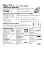
18” Woodworking Bandsaw
Model: 10-340
Owner’s Manual
For more information:
For Parts or Questions:
Record the serial number and date of purchase
in your manual for future reference.
Serial number:
Date of purchase:
Part #10-340M2

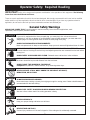
Operator Safety: Required Reading
IMPORTANT! Safety is the single most important consideration in the operation of this equipment. The following
instructions must be followed at all times.
There are certain applications for which this tool was designed. We strongly recommend that this tool not be modified
and/or used for any other application other than that for which it was designed. If you have any questions about its
application, do not use the tool until you have contacted us and we have advised you.
General Safety Warnings
KNOW YOUR POWER TOOL. Read the owner’s manual carefully. Learn the tool’s applications, work
capabilities, and its specific potential hazards.
ALWAYS KEEP VISITORS AWAY FROM RUNNING MACHINES.
All visitors should be kept a safe distance from the work area.
ALWAYS MAKE THE WORKSHOP CHILDPROOF.
Childproof with padlocks, master switches, or by removing starter keys.
NEVER OPERATE A TOOL WHILE UNDER THE INFLUENCE OF DRUGS,
MEDICATION, OR ALCOHOL.
ALWAYS WEAR PROPER APPAREL.
Never wear loose clothing or jewelry that might get caught in moving parts. Rubber-soled footwear is
recommended for the best footing.
ALWAYS USE SAFETY GLASSES AND WEAR HEARING PROTECTION.
Also use a face or dust mask if the cutting operation is dusty.
NEVER OVERREACH.
Keep your proper footing and balance at all times.
ALWAYS GROUND ALL TOOLS.
If your tool is equipped with a three-pronged plug, you must plug it into a three-hole electric
receptacle. If you use an adapter to accommodate a two-pronged receptacle, you must attach the
adapter plug to a known ground. Never remove the third prong of the plug.
ALWAYS AVOID DANGEROUS ENVIRONMENTS.
Never use power tools in damp or wet locations. Keep your work area well lighted and clear of clutter.
ALWAYS REMOVE THE ADJUSTING KEYS AND WRENCHES FROM TOOLS AFTER USE.
Form the habit of checking to see that keys and adjusting wrenches are removed from the tool before
turning it on.
ALWAYS KEEP YOUR WORK AREA CLEAN. Cluttered areas and benches invite accidents.
NEVER STAND ON TOOLS.
Serious injury could occur if the tool is tipped or if the cutting tool is accidentally contacted.
2

ALWAYS CHECK FOR DAMAGED PARTS.
Before initial or continual use of the tool, a guard or other part that is damaged should be checked to
assure that it will operate properly and perform its intended function. Check for alignment of moving
parts, binding of moving parts, breakage of parts, mounting, and any other conditions that may affect
its operation. A guard or other damaged parts should immediately be properly repaired or replaced.
ALWAYS DISCONNECT TOOLS.
Disconnect tools before servicing and when changing accessories such as blades, bits, and cutters.
ALWAYS AVOID ACCIDENTAL STARTING.
Make sure switch is in “OFF” position before plugging in cord.
NEVER LEAVE TOOLS RUNNING UNATTENDED.
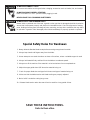
1. Always allow the Bandaw blade to stop before removing scrap pieces from table.
2. Always keep hands and fingers away from the blade.
3. Never attempt to saw stock that does not have a flat surface, unless a suitable support is used.
4. Always hold material firmly and feed it into the blade at a moderate speed.
5. Always turn off the machine if the material is to be backed out of an uncompleted cut.
6. Adjust the upper guide about 1/8” above the material being cut.
7. Check for proper blade size and type for thickness and type of material being cut.
8. Make sure that the blade tension and blade tracking are properly adjusted.
9. Make “relief” cuts before cutting long curves.
10. Release blade tension when the saw will not be used for a long period of time.
Special Safety Rules For Bandsaws
SAVE THESE INSTRUCTIONS.
Refer to them often.
3

Safety Warnings..................................................................................................................................................2 -3
Bandsaw Safety Rules ..........................................................................................................................3
Specifications ........................................................................................................................................4
Contents of Package ............................................................................................................................5
Unpacking and Setup ...........................................................................................................................5
Loose Parts ...........................................................................................................................................6
Getting To Know Your Bandsaw ............................................................................................................7
Assembly ..............................................................................................................................................8
Table Assembly .....................................................................................................................................8
Rip Fence Assembly .............................................................................................................................8
Hand-Wheel Assembly .........................................................................................................................8
Setting 90
o
Table Stop ...........................................................................................................................9
Tilting the Table .....................................................................................................................................9
Tracking Blade ......................................................................................................................................9
Adjusting Blade Tension .......................................................................................................................9
Upper Blade Guide Adjustment ..........................................................................................................10
Lower Blade Guide Adjustment ..........................................................................................................10
Rip Fence Scale Adjustment ...............................................................................................................10
Cutting Height Adjustment ..................................................................................................................10
Changing Blade Speed .......................................................................................................................11
Replacing Blades ................................................................................................................................11
Resawing .............................................................................................................................12
Operation ............................................................................................................................................12
Maintenance .......................................................................................................................................12
Troubleshooting .........................................................................................................................13-14
Changing Bandsaw Tire ......................................................................................................................................14
Wiring Diagram ...................................................................................................................................14
Parts Diagram ................................................................................................................................15-17
Parts List ........................................................................................................................................18-19
How To Guide .....................................................................................................................................20
Warranty .............................................................................................................................................21
Table of Contents
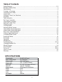
SPECIFICATIONS
4
18-3/8” (467 mm)
12” (305 mm)
142” (3607 mm)
1/4” – 1-1/4”(6-32 mm)
21”x 19” (534 mm x 483 mm)
Left-10
o
Right-45
o
1510 ft/min or 3220 ft/min
2 HP
12.5
220
396 lbs
Throat width
Max. cutting depth
Blade length
Blade width
Table size
Table tilt
Blade speeds
Motor
Amps
Volts
Net weight

5
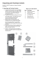
Unpacking and Checking Contents
Model 10-340 18” Bandsaw is shipped complete
in one box.
1. Unpacking and Checking Contents
a. Separate all “loose parts” from packaging
materials and check each item with “Table
of Loose Parts” to make sure all items are
accounted for, before discarding any
packaging material.
b. Thread hoist ring into threading hole on top
of Bandsaw frame. This allows the user to
connect a properly secured hoist
mechanism to lift the Bandsaw.
c. With the help of another person or by
installing hoist ring, unbolt the Bandsaw
from the packing pallet. Properly lift the
Bandsaw off the packing pallet and place on
level floor.
d. Remove protective oil that is applied to the
table. Use any ordinary house hold type
grease and spot remover.
e. Apply a coat of paste wax to the table to
prevent rust. Wipe all parts thoroughly with a
clean dry cloth.
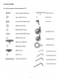
TABLE OF LOOSE PARTS
Item Part Name Qty
A Bandsaw Assembly 1
B Table w/insert 1
C Rip fence Assembly 1
D Front guide rail 1
E Rear guide rail 1
F Owner’s manual 1
G Box of loose parts 1

6
Loose Parts
List of loose parts in the box marked “G”

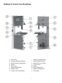
Getting To Know Your Bandsaw
7
A. Hoist Ring
B. Tension Indicator Window
C. Blade Tension Hand-wheel
D. Switch
E. Rip Fence
F. Speed Hand-wheel
G. Blade Guide
H. Guide Post Hand-Wheel
I. Blade Tracking Window
J. Quick Release Lever
K. Guide Post Lock Knob
L. 4” Dust Ports
M. Motor
N. Table Tilting Knob
O. Blade Tracking Knob
P. Tool holder

Figure 1
Figure 4
8
A
B
Figure 2
Figure 3
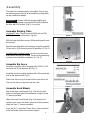
Assembly
The machine is supplied partly assembled. Prior to use,
the following items have to be assembled: working table,
rip fence and hand-wheels.
WARNING! To ensure sufficient upright stability and
safety of this Bandsaw, you need to bolt the Bandsaw to
the floor with M10 screws.(Fig 1) (not supplied)
Assemble Working Table
Installing 90°stop: Thread screw (m8x20) and nut (M8-
1.25) to the bottom of the table. (Fig. 4A)
With the help of another person, lift the working table onto
the trunnion.
Mount the working table to the trunnion using the supplied
(4) hex bolts, (4) lock washers and (4) washers (A--Fig.2).
Installing Table Leveling Screw: Insert hex socket screw
and washer through top of table. Place bushing and wing
nut from under the table and tighten. (B--Fig. 2)
Assemble Rip Fence
Install the rear fence rail to the table with (2) M6-1.0 x 20
hex bolts and (2) flat washers M6 (Fig. 3).
Install the front fence rail to the table with (4) thumbscrews
and (4) flat washers M8 (Fig. 3).
Make sure the end cap is locked into the rear fence rail.
Then set the fence on the front and rear rails.
Assemble Hand-Wheels
Attach the large crank handle (Fig. 4) to the rack and
pinion on the upper part of the bandsaw, using the 5mm
“L” wrench provided.
Attach the small crank handle (Fig. 4) to the belt and
speed control rod on the lower right side of the bandsaw,
using the 5mm “L” wrench provided.
Place the (4) “L” wrenches (3mm, 4mm, 5mm and 6mm)
in the tool holder on the rear column support.

Figure 5
Figure 6
Figure 7
Figure 8
9
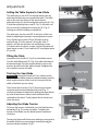
Adjustment
Setting the Table Square to Saw Blade
The table may be set at 90° to the saw blade sides by
adjusting the table stop screw under the table. The table
stop screw rests on the top of the quick release
adjustment stop. By first loosening the locking nut (A--Fig.
5) and then adjusting the screw (B--Fig. 5), the table can
be set correctly. Retighten the locking nut (A--Fig. 5)
making sure that the setting is maintained.
The table may also be set at 90° to the back of the saw
blade by adjusting the trunnion micro adjustment screws.
First, slightly loosen parts 97 and 98 (refer to parts
explosion pg. 16 in this manual). Using the 3mm “L”
wrench, turn the rear trunnion micro adjusting screws.
(Clockwise will raise these screws; counterclockwise will
lower these screws). Check table for 90° and tighten parts
97 and 98.
Tilting the Table
Loosen the lock handle (A--Fig. 6) on the table trunnion.
Turn the table tilting knob (B--Fig. 6) to adjust the table to
the desired angle. Use the angle indicator scale on the
trunnion bracket to find the desired angle. Retighten the
lock handle to secure the table.
Tracking the Saw Blade
WARNING! Unplug the Bandsaw. First, make sure the
upper and lower blade guides are adjusted away from the
blade and the tension scale is set to correspond to the
width of the blade you are using.
Then loosen the lock lever (Fig. 7) by turning it counter
clockwise and turn the blade tracking knob (Fig. 7)
clockwise/counterclockwise while turning the upper wheel
by hand at least three rotations until the blade tracks
centered on the wheel. Finally, tighten the lock lever and
close the doors.
Adjusting the Blade Tension
To loosen the tension of the blade, turn the blade tension
handwheel (Fig. 8) counter clockwise. To tighten the
tension of the blade, turn the blade tension handwheel
clockwise.
Tension the blade until the tension readings correspond to
the width of blade you are using by viewing through the
tension indicator window (Fig. 8).

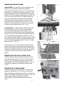
Adjusting the Blade Guides
Upper Guides: To adjust the upper blade guides, first
position the roller guides relative to the blade by
loosening the locking hex screw (A--Fig. 9) and moving
the guide carrier until the roller guides are approx. 1/16”
behind the gullets of the blade. Next set the roller guides
to within 1/32” of the blade by releasing the screw (B--Fig.
9) on each side of the blade. Do not set the guides too
close, as this will adversely affect the life of the blade.
Finally, adjust the thrust bearing to be just clear of the
back of the blade by unlocking the hex nut (C--Fig. 9).
When the correct adjustment is reached, lock the thrust
bearing in position with the hex nut (A--Fig. 9).
Lower Guides: To adjust the lower blade guides, first
loosen the hex nut (A--Fig. 10) then move the guide
carrier casting to allow the front to be approx. 1/16”
behind the gullets of the Bandsaw blade and tighten the
hex nut (A--Fig. 10). Next set the roller guides to within 1/
32” of the blade by releasing the screw (B--Fig. 10) on
each side of the blade. Adjust the thrust bearing to be just
clear of the back of the blade by unlocking the hex nut (C--
Fig. 10), and turning adjusting knob (D--Fig. 10). Finally,
tighten hex nut (C--Fig. 10).
Make sure doors are closed, turn the bandsaw on and
inspect that the upper, lower and thrust bearings are not
turning. All bearings should not turn unless pressure from
workpiece is applied to the blade. If bearings are turning
under no pressure, repeat steps to adjust the blade
guides.
Adjusting the Rip Fence Guide Scale
Slide the rip fence against the blade along the rail and
loosen the indicator screw (A--Fig. 11). Then move the
scale (B--Fig. 11) sideways and align the zero on the
scale with the line on the magnifying window (C--Fig. 11).
Retighten the indicator screw when the adjustment is
correct.
Adjusting the Cutting Height
Loosen the guidepost lock knob (Fig. 12) and turn the
guidepost handwheel (Fig. 12) to raise or lower the
guide post/upper blade guide assembly to the desired
height. Then tighten the guidepost lock knob. Note: The
bottom edge of the guide bearings should be
approximately 1/4”above the top surface of the work
piece.
10
Figure 9
Figure 10
Figure 11
Figure 12

11
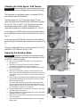
Changing the Blade Speed / Belt Tension
WARNING! Before changing the speed, always make sure
the machine has been unplugged from the electrical supply.
This Bandsaw has two blade speeds, low speed (1510 ft/
min) and high speed (3220 ft/min).
The lower wheel (A--Fig. 13) has two integral “V” form
pulleys, and the motor shaft has a twin multi-vee form pulley
(B--Fig. 13). The “V” belt (C--Fig. 13) passes around the
wheel pulley and the motor pulley. The belt tension is
released and applied by using the handwheel (D--Fig. 13).
For the high speed (3220 ft/min), the belt should be fitted to
the rear pulley on both the motor and the wheel. As shown in
Fig. 13.
For the low speed (1510 ft/min), the belt should be fitted to
the front pulley on both the motor and wheel. As shown in Fig.
13.
To properly adjust belt tension, turn hand-wheel (D--Fig. 13)
until there is 1/2” deflection in the “V” belt.
Replacing the Bandsaw Blade
WARNING! Unplug the machine from the electrical supply.
This ensures that the Bandsaw will not accidentally turn on if
the ON/OFF switch is bumped.
a) Open the top and bottom wheel doors by turning the door
locking knobs.
b) Remove the rip fence rail from the front of the table by
loosening the 4 thumbscrews (Fig. 3 on page 8).
c) Release the blade tension by rotating the quick release lever
(Fig. 14) clockwise.
d) Remove the saw blade by feeding it through the slot in the
table, upper and lower blade guides and the slot in the spine of
the machine, being careful not to cut yourself. Wear gloves for
protection.
e) When fitting the new blade ensure the blade teeth are pointing
downwards and towards you at the position where the blade
passes through the table.
f) Re-tension the new blade by rotating the quick release lever
(Fig. 14) counterclockwise and check the blade tracking. The
blade should run in the center of the wheel. Refer to “Tracking
the Saw Blade” on page 6 for more details.
g) Reset the blade guides as described in the section “Adjusting
the Blade Guides” on page 10.
h) Reset the blade tension as described in the section “Adjusting
the Blade Tension” on page 9.
i) Replace the rip fence guide, and retighten the 4 thumb-screws
(Fig. 3 on page 8).
j) Close and lock both the wheel doors before reconnecting the
power supply.
Figure 13
Figure 14

12
Re-sawing
For re-sawing, attach the 3/8” x 3” post to the slot on the fence. Position the re-saw bar so that it is
aligned with the front of the blade. The re-saw bar helps to correct any blade wandering during re-sawing
operations.
Operation
The blade cuts on a continuous down-stroke.
With both hands, firmly hold the workpiece down on the table, and feed it towards the blade slowly,
keeping your hands away from the blade.
For best results the blade must be sharp. A dull blade will not cut correctly, especially when straight
cutting, and causes excess pressure to be applied on the rear guide bearings.
Select the right blade for the job, depending on the thickness of the wood and the cut to be made.
The thinner and harder the wood, the finer the teeth of the blade should be. Use a fine tooth blade for
cutting sharp curves.
The machine is especially suited for cutting curves, but will also make straight cuts. When cutting,
follow the design marked out by pushing and turning the workpiece evenly.
Do not attempt to turn workpiece without pushing it as this may cause the workpiece to get stuck, or
the blade to bend.
For straight cuts, use the fence provided to feed the workpiece along the blade slowly and in a
straight line.
Maintenance
CA CA
CA CA
CA
UTION!UTION!
UTION!UTION!
UTION! BEFORE CLEANING OR CARRYING OUT MAINTENANCE WORK, DISCONNECT
THE MACHINE FROM THE POWER SOURCE (WALL SOCKET). NEVER USE WATER OR OTHER
LIQUIDS TO CLEAN THE MACHINE. USE A BRUSH. REGULAR MAINTENANCE OF THE
MACHINE WILL PREVENT UNNECESSARY PROBLEMS.
Keep the table clean to ensure accurate cutting.
Keep the outside of the machine clean to ensure accurate operation of all moving parts and prevent
excessive wear.
Keep the ventilation slots of the motor clean to prevent it from overheating.
Keep the inside (near the saw blade, etc.) clean to prevent accumulation of dust.

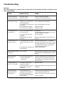
Troubleshooting
WARNING!
FOR YOUR OWN SAFETY, ALWAYS TURN OFF AND UNPLUG THE MACHINE BEFORE CARRYING OUT ANY
TROUBLESHOOTING.
13
TROUBLE
The machine does not
work when switched on.
The blade does not move
with the motor running.
The blade does not cut
in a straight line.
The blade does not cut,
or cuts very slowly.
Sawdust builds up inside
the machine.
Sawdust inside the
motor housing.
The machine does not
cut at 45
o
or 90
o
angles.
The blade cannot be
properly positioned on
the bandwheels.
PROBABLE CAUSE
1. No power supply.
2. Defective switch.
1. The quick release lever or
blade tension handwheel has
not been tightened.
2. The blade has come off one of
the wheels.
3. The saw blade has broken.
4. The drive belt has snapped.
1. Fence for cutting not used.
2. Too fast feed rate.
3. The blade teeth are dull or
damaged.
4. Blade guides not suitably
adjusted.
1. The teeth are dull, caused by
cutting hard material or long
use.
2. The blade was mounted in the
wrong direction.
1. This is normal
1. Excessive dust build-up on
the machine exterior
components.
1. The table is not at right
angles to the blade.
2. The blade is dull or too much
pressure was put on the
workpiece.
1. The wheels are not in
alignment. Defective bearing.
2. The blade tracking knob
hasn’t been properly adjusted.
3. Inferior blade.
REMEDY
Check the cable for breakage.
Contact your local dealer for repair.
Switch off the motor, tighten the quick release
lever or blade tension handwheel.
Open the hinged door and check.
Replace the blade.
Replace the belt.
Use a fence.
Put light pressure on the workpiece & make
sure the blade does not bend.
Use a new blade.
Adjust the blade guides (see the section on
page 10).
Replace the blade, use a 6 T.P.I. blade for
wood and soft materials. Use a 14 T.P.I. blade
for harder materials. A 14 T.P.I. blade always
cuts slower due to the finer teeth and the
slower cutting performance.
Fit the blade correctly.
Clean the machine regularly. Open the hinged
door and remove the sawdust with a vacuum
cleaner.
Clean the ventilating slots of the motor with a
vacuum cleaner. From time to time remove
the sawdust to prevent it from being sucked
into the housing
Adjust the table.
Replace the blade or put less pressure on the
workpiece.
Contact Technical Support @ 877-884-5167
Adjust the knob (see the section on page 9).
Replace the blade.
For parts or technical questions contact: [email protected] or 877-884-5167.

Wiring Diagram
WARNING! This machine must be grounded.
Replacement of the power supply cable should only be done by
a qualified electrician.
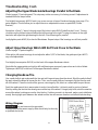
Adjusting the Upper Blade Guide Bearings Parallel to the Blade
(Refer to page 17 parts diagram) This step may not be necessary, it is factory preset. If adjustment is
needed follow the steps below.
First slightly loosen part #162 (4 each) cap screw on rear of upper Bandsaw housing (see page 17 in
parts diagram) This will allow you to adjust the micro adjustment screws on part #164 (Guide
Bracket).
Next place a 3mm “L” wrench through one of the holes in part #169 (Guide Bracket Cover). Turning
clockwise on the left two holes will adjust the left bearings to the right. Turning clockwise on the right
two holes will adjust the right bearings to the left. Check bearings for parallel.
Lastly tighten parts #162 (4) on back of Bandsaws. Repeat steps if the bearings are still not parallel.
Adjust Upper Bearings Which Will Not Track Close to the Blade
(Refer to page 17 parts diagram)
If the right or left upper bearings do not adjust to within 1/32” of the blade, the guide post (part #157)
may need adjustment.
First slightly loosen parts #162 (4) on the back of the upper Bandsaw cabinet.
Next slide the upper guide post right or left until bearings are properly spaced on each side of blade.
Tighten part #162 (4) on the back of the upper Bandsaw cabinet.
Troubleshooting Cont.
Changing Bandsaw Tire
Use a putty knife to get underneath the tire and pull it up and away from the wheel. Work the putty knife all
the way around the wheel to loosen the tire. Then, use the putty knife as leverage to flip the tire over and
off of the wheel. Clean the inside of the groove, removing any dirt, debris or cement with lacquer thinner.
Soak the replacement tire in warm water to make it more flexible. Let tire dry and lay on top of wheel.
Start by setting the tire into the wheel groove at the top of the wheel. Using a putty knife, work the new tire
around the wheel, making sure not to slice the tire. If rubber cement is to be used, make sure to distribute
evenly. Having high spots between the wheel and the tire will cause a vibration and effect blade tracking.
14
220V
Power
Supply
220V Motor Wires
1
2
3
4

15
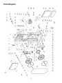
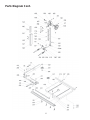
Parts Diagram

16

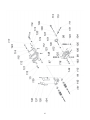
Parts Diagram Cont.
17

18
Parts List
51 Bushing
52 Rubber Door Grommets
53 Special Hex Screw
54 Quick Stop Support
55 Upper Wheel Cover
56 Hex Bolt M6-1.0x25
57 Flat Washer M6
58 Brush
59 Hex Bolt M6-1.0x25
60 Star Handle
61 Nylon Nut M6-1.0
62 Strain Relief
63 Strain Relief Nut
64 Small Handwheel
65 Threaded Rod
66 Knob Bolt M10-1.5x20
67 Knob Bolt M10-1.5x53
68 Threaded Handle M10-1.5
69 Cam
70 Pillow Block
71 Shaft End
72 Rod
74 Shaft
75 Cap Screw M8-1.25x20
76 Shaft-V Belt Pulley
77 V Belt Pulley
78 Circlip Ring
79 Set Screw M8-1.25x20
80 Hex Nut M8-1.25
81 Lower Wheel Shaft
82 Motor
83 Hex Bolt M6-1.0x25
84 Lock Washer M8
85 Lock Lever
86 Cap Screw M8-1.25x20
87 Strain Relief Plate
88 Phlp HD SCR w/Flange
89 Sliding Cover
90 Key 5x5x35
91 Hex Bolt M8-1.0x20LH
92 Motor Pulley
93 V-Belt
94 Hex Bolt M6-1.0x30
95 Lower Wheel Cover
96 Small Wheel Cover
97 Bolt M12-1.75x40
98 Hex Bolt M12x35
99 Hex Nut M12-1.75
3 Tube
4 Ring
5 Frame
6 Set Screw M6-1.0x10
7 Switch Cord
8 Flat Washer M5
9 Power Cord
10 Hex Nut M6-1.0
11 Pointer
12 Step Screw
13 Upper Shaft
14 Roll Pin 5x36
15 Upper Wheel Shaft Hinge
16 Upper Wheel Shaft
17 Bushing
18 Bearing 6204
19 Upper Wheel
20 Int Retaining Ring M47
21 Flat Washer M8
22 Hex Bolt M8-1.25x30
23 Saw Blade
24 Board
25 Hex Bolt M6-1.0x30
26 Tire
27 Lower Wheel
28 Idle Pulley
29 Hex Nut M27x2
30 Lock Washer 27
31 Motor Cord
32 Spring
33 Roll Pin 3x16
34 Block
35 Bearing 51201
36 Switch
37 Big Handwheel
38 Adjusting Rod
39 Nut
40 Star Washer M5
41 Resaw Bar
42 Phlp HD SCR w/Flange M5x12
43 Switch Plate
44 Hex Bolt M8-1.25x16
45 Flat Washer M8
46 Upper Wheel Sliding Bracket
47 Hex Bolt M6-1.0x25
48 Rivet
49 Hex Bolt M6-1.0x20
50 Clear Window
Part No. Description Part No. Description

19
156 Rack
157 Upper Guide Post
158 Big Crank Handle
159 Hex Bolt M6-1.0x20
160 Bushing
161 Bushing
162 Cap Screw M8-1.25x20
163 Spring Washer 8
164 Guide Bracket
165 Worm Cylinder
166 Fixed Plate
167 Gear
168 Fixed Bolt
169 Guide Bracket Cover
170 Hex Bolt M8-1.25x16
171 Phlp M4-0.7x8
176 Bushing
201 Front Fence Rail
202 Adjustable Base
203 Fixed Shaft
204 Shaft
205 Spring Piece
206 Bracket
207 Support Tube
208 Internal Sheath
209 Handle
210 End Cap
211 Convex Window
212 Cap Screw M6-1.0x55
213 Lock Mechanism
214 Rear Fence Rail
215 Hex Nut M8-1.25
216 Bushing
217 Pan Head Screw
220 Fixing Screw
221 Scale
222 Hex Nut M6-1.0
223 Wing Nut
224 Cap Screw M6-1.0x16
225 Hex Bolt M6-1.0x20
226 Pan Head Screw M4-0.7x5
227 Flat Washer M6
228 Flat Washer M8
229 Thumb Screw
230 Nut M8
231 Hex Bolt M8-1.25x25
232 Owner’s Manual
233A Hex Screw
250 Warranty Card
100 Small Gear
101 Table Tilting Knob
102 Trunnion Support Bracket
103 Lock Washer 12
104 Flat Washer M10
105 Hex Bolt M6-1.0x20
106 Hex Bolt M6-1.0x50
107 Pillow Block
108 Hex Nut M6-1.0
109 Adjustment Bolt M6-1.0
110 Bearing 6201
111 Cap Screw M8-1.25x25
112 Flat Washer M8
113 Flat Washer M8
114 Phlp HD SCR M5-0.8x6
115 Gear Plate
116 Nylon Nut M8-1.25
117 Phlp HD SCR M5-0.8x6
118 Lock Handle
119 Flat Washer M5
120 Pointer
121 Trunnion Plate
122 Small Crank Handle
123 Hex Bolt M8-1.25x16
124 Carriage Bolt M8-1.25x80
125 Micro Adjusting Screws
126 Table
127 Table Insert
128 Hex Socket Screw M6-1.0x50
130 Left Cover
131 Hex Bolt M8-1.25x45
134
Lower Blade Guide Support
135 Right Cover
136 Hex Bolt M5-0.8x10
137 Flat Washer M5
138 Protective Cover
140 Step Screw
141 Flat Washer
142 Sliding Plate
143 Retaining Ring S15
144 Bearing 6201
145 Upper Blade Guide Support
146 Guide Ring
148 Carriage Bolt M8-1.25x85
149 Bushing
150 Adjusting Bar
151 Tube
152 Hex Bolt M6-1.0x25
153 Upper Guide Support Block
154 Phlp HD SCR M5-0.8x10

20
Page is loading ...
Page is loading ...
-
 1
1
-
 2
2
-
 3
3
-
 4
4
-
 5
5
-
 6
6
-
 7
7
-
 8
8
-
 9
9
-
 10
10
-
 11
11
-
 12
12
-
 13
13
-
 14
14
-
 15
15
-
 16
16
-
 17
17
-
 18
18
-
 19
19
-
 20
20
-
 21
21
-
 22
22


Rikon Power Tools 10-340 User manual
- Category
- Power tools
- Type
- User manual
Ask a question and I''ll find the answer in the document
Finding information in a document is now easier with AI
Related papers
-
Rikon Power Tools 10-345 User manual
-
-
-
-
-
-
-
Rikon Power Tools 10-324 User manual
-
-
Other documents
-
 Zippity Outdoor Products ZP19002 Specification
-
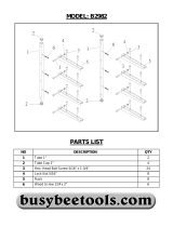 Craftex B2982 Owner's manual
-
Craftsman 119.214 User manual
-
-
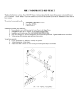 MK Diamond Products MK-170 Owner's manual
-
-
Rikon 10-325 Owner's manual
-
King Canada KC-1401FX User manual
-
Wen 3970T User manual
-
King Canada KC-1433FXR User manual


