BMW E60 User manual

Type
User manual

BMW E60: Experience driving pleasure like never before. With its lightweight aluminum front end, this vehicle boasts enhanced agility and performance. Discover the epitome of luxury with a spacious cabin featuring cutting-edge technology. Embrace every journey with confidence thanks to advanced safety systems and enjoy unparalleled comfort in its refined interior.

BMW E60: Experience driving pleasure like never before. With its lightweight aluminum front end, this vehicle boasts enhanced agility and performance. Discover the epitome of luxury with a spacious cabin featuring cutting-edge technology. Embrace every journey with confidence thanks to advanced safety systems and enjoy unparalleled comfort in its refined interior.

Subject Page
E60 Complete Vehicle
Objectives of the Module . . . . . . . . . . . . . . . . . . . . . . . . . . . . . . . . . . . . .2
Purpose of the System . . . . . . . . . . . . . . . . . . . . . . . . . . . . . . . . . . . . . .3
Brief History . . . . . . . . . . . . . . . . . . . . . . . . . . . . . . . . . . . . . . . . . . . . . . .3
Highlights and Design . . . . . . . . . . . . . . . . . . . . . . . . . . . . . . . . . . . . . . .5
System Components . . . . . . . . . . . . . . . . . . . . . . . . . . . . . . . . . . . . . . . .7
Vehicle Data Views . . . . . . . . . . . . . . . . . . . . . . . . . . . . . . . . . . . . . . . . .10
Technical Da t a . . . . . . . . . . . . . . . . . . . . . . . . . . . . . . . . . . . . . . . . . . . .12
Front Bumper System
Removing and Refitting . . . . . . . . . . . . . . . . . . . . . . . . . . . . . . . . . . . . .14
Headlights . . . . . . . . . . . . . . . . . . . . . . . . . . . . . . . . . . . . . . . . . . . . . . .16
Rear Bumper System
Rear Light Clusters . . . . . . . . . . . . . . . . . . . . . . . . . . . . . . . . . . . . . . . .19
Removing and Refitting . . . . . . . . . . . . . . . . . . . . . . . . . . . . . . . . . . . . .20
Luggage Compartment and Door Attaching Hardware
Hinges . . . . . . . . . . . . . . . . . . . . . . . . . . . . . . . . . . . . . . . . . . . . . . . . . .22
Exterior Door Handles . . . . . . . . . . . . . . . . . . . . . . . . . . . . . . . . . . . . . .23
Tab le of Co nt en ts
E60 Complete Vehicle
Initial Print Date: 08/03 Revision Date: 09/03
2
E60 Complete Vehicle
Model: E60 - 525i, 530i, 545i
Production: Start of Production MY 2004
This intent of this workbook is to assist you with diagnosis and testing in addition to the
detailed information found in the the latest Diagnosis and TIS of the DISplus/GT1.
This section will be instructor led for a brief review of the E60 Complete Vehicle. You are
encouraged to use this workbook with the latest Diagnosis and TIS information to make
notes during diagnosis and testing of the
nneeww ccoommppoonneennttss//ssyysstteemmss ooff tthhee EE6600..
This will
be valuable to you as supplementary information or a memory refresher when performing
diagnosis in the future.
NNoottee::
For more in depth and detailed information about the E60 Complete Vehicle, refer to
the ST046 E60 Complete Vehicle training CD.
For additional and updated information, always refer to:
www.bmwcenternet.com
- Diagnosis and TIS information/updates
- Service Information Bulletins
- DCS messages
Objectives:
After completion of this module you will be able to:
Properly remove, install and adjust the front bumper system
Properly remove, install and adjust the head lights
Properly remove, install and adjust the rear light clusters
Properly remove, install and adjust the rear bumper system
Properly remove and install the exterior door handles
3
E60 Complete Vehicle
T
Purpose of the System
The E60 is the fifth edition of the BMW 5 Series replacing the E39. The automobile revo-
lution in design and engineering initiated by the E65/E66 now finds its logical continuation
in the E60. Virtually all the significant innovations of the 7 Series are also offered in the 5
Series.
However the E60 also offers new features of its own, some of which will make their appear-
ance in other model series in due time. The most important of these new features are:
• Active steering system, whose variable reduction ratio adapts itself to the relevant driving
situation.
Lightweight design with a front-end structure of bonded and riveted aluminum (GRAV).
Head-up display, which projects the most important information such as vehicle speed
or navigation arrows in the form of a virtual image directly into the driver's field of vision.
Adaptive directional headlight system, which adapts itself continuously to the steering
angle and thus illuminates the approaching bend.
BMW 5 Series - Brief History
Thhee EE1122
The first BMW to be christened the "5 Series" was the E12.
In 1972 this model in the form of the "520" began the system
of model designation which has remained to this day: The
first number stands for the model series, while the second
and third numbers represent the cubic capacity.
A total of 702,242 E12s from the 518 to the 535i were pro-
duced in Dingolfing and Munich until 1985.
KT-9494
4
E60 Complete Vehicle
T
T
T
Thhee EE2288
The successor model E28, which at first glance appeared to
have only minor modifications, brought the production fig-
ures to 723,001 with the model designations 518i to 535i
between 1980 and 1990.
From January 1983 production of the 5 Series - with the
exception of the M5 offered for the first time - was confined
exclusively to Dingolfing. 1983 was also the year when the
524td became the first 5 Series to feature a diesel engine.
Thhee EE3344
The 3rd generation 5 Series registered a major increase in
production volume: Between 1987 and 1996 a total of
1,330,661 E34s came off the Dingolfing production line. The
engine range of four- and six-cylinder models was extended
to include a V8 (518i to 540i) and rounded off by diesel
engines (525td and 525tds) and the high-performance M5.
A second bodystyle was also introduced in the form of the 5
Series touring, which also included a version that ran on liq-
uefied petroleum gas (518g touring). A four-wheel drive was
also produced in both saloon and touring versions in the form
of the 525ix.
Thhee EE3399
The current 5 Series was launched in 1995, of which to date
1,362,884 have been built (as at: 30 September 2002). In
addition to the standard saloon and touring, there is also a
safety saloon version of the E39 (540i Protection).
The engine options available range from the 518i to the 540i
(diesel: 520d to 530d), as well as the M5.
KT-9490
KT-9489
KT-9473
5
E60 Complete Vehicle
The new E60 - Highlights and Design
The BMW Group's new design strategy with its broadening of the family resemblance lends
future BMW model series still more individual character. It is thus possible for the E60 to
embody the values of the 3 Series (dynamic and sporty) as well as those of the 7 Series
(successful, top of the range and sporty) and yet remain an individual and original car with-
in the scope of traditional BMW model series.
Unlike its competitors - and also its predecessors at BMW in previous years - the new 5
Series demonstrates its own clearly recognizable lines: The unique character of the individ-
ual model series within the overall range of the BMW marque will in future be increasingly
accentuated. The new 5 Series therefore comes across neither as a small 7 Series nor as
a big 3 Series.
The front end makes a bold and dynamic state-
ment.
The most striking features are the new twin
headlights and the dramatically sloping hood
lines on both sides which now already begin at
the level of the earlier swage line.
Flowing lines run from the headlights along the
sides to the rear end of the E60.
KT-11013
KT-11012
6
E60 Complete Vehicle
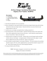
The side line is a logical extension of the front-end design. Thus the E60 is the first BMW
model not to have the previously typical side swage line. Its place is taken by a character
line, an edge of light which lends the side view a whole new character. Various light reflec-
tions above and below this line produce a play of light and shadow, thereby giving the
impression of a very low side panel.
The transition from the hood to the side panel occurs in the imaginary extension of the
character line.
TThhuuss tthhee EE6600 hhaass tthhee lloowweesstt ffrroonntt eenndd eevveerr ooff aannyy BBMMWW..
The sculpture-like
appearance of the side view is consolidated by the fact that there are no protective strips
in the door areas.
Despite its increased height, the passenger cell has a coupe-like appearance thanks to the
sweeping design of the C-pillar. Short overhangs and generously dimensioned wheel arch-
es accentuate the dynamic, bold overall appearance. The clear shaping of the wheel lips
as a typical BMW design element emphasize the wide track of the E60.
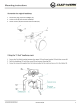
The rear end conveys an at once wide and compact effect due to the fact that there are no
visible joints. Under the high deck lid with integrated spoiler lies
tthhee bbiiggggeesstt lluuggggaaggee ccoomm--
ppaarrttmmeenntt iinn tthhee ccuurrrreenntt BBMMWW rraannggee..
The rear lights are mounted in brilliant optical hous-
ings, the tops of which are sloping in appearance.
The large rear apron of the E60 is subdivided by additional reflector elements and thus
gives the impression of being lighter.
A distinctive diffuser lip not only ensures opti-
mum aerodynamics but also reduces the
amount of dirt which accumulates on the vehi-
cle rear end.
The overall impression communicates an
unmistakable sense of the E60's power and
strength to road-users driving behind it.
KT-11014
KT-11016
7
E60 Complete Vehicle
System Components
Body Structure
The body dimensions have been increased to improve roominess in the rear compartment
(+ 5 cm knee room) and to increase the luggage compartment capacity (at 520 L the largest
capacity of all the BMW vehicles including the E65).
In order to make the E60 signifi-
cantly lighter than the current 5
Series, BMW designed a
"reduced-weight aluminum front
end" (GRAV).
The front end consists almost
entirely of aluminum while the
transition to steel occurs in the
front bulkhead area. Aluminum
components are shown in darker
shaded (front clip) section.
The weight saving at the front end not only reduces the total weight of the vehicle but is
also a significant factor in the E60 attaining the ideal axle-load distribution of 50/50.
On the one hand, an aluminum body sec-
tion offers reduced shielding against
external electrical radiation, making it nec-
essary for separate shielding of the wiring
harnesses and electronic control units.
On the other hand, riveted and bonded
aluminum components do not always
provide a guaranteed circuit to ground.
This results in individual front end compo-
nents being connected (in production)
with small EMC safety weld seams and in
the event of repair, with grounding straps.
1. Spring Support
2. Engine Support
3. Bulkhead carrier support
4. Outer connection (steel)
5. Bulkhead Cross Member
6. Bulkhead
7. Inner A-pillar (steel)
KT-11776
KT-11777
8
E60 Complete Vehicle
The transition from the aluminum front engine
support rail to the steel rail section joint (connec-
tion) is produced by bonding and punch riveting.
To i n c rease c o n d u c t i v i t y, gro u n d points a re l o c a t -
ed on the two rails and are connected with a
ground strap.
In addition to the underhood strut tower V- struts
(2 lower left), the bumper carrier (1 lower right)
and thrust panel (2 lower right) provide addition-
al reinforcement and structural rigidity.
NNoottee:: TThhee VV--ssttrruuttss,, bbuummppeerr ccaarrrriieerr aanndd tthhrruusstt ppaanneell m
b
muusstt bbee iinnssttaalllleedd aanndd pprrooppeerrllyy ttoorrqquueedd
beeffoorree tthhee vveehhiiccllee iiss ddrriivveenn.. IIff nnoott,, tthhee rriiggiiddiittyy ooff tthhee ffrroonntt eenndd wwiillll bbee ccoonnssiiddeerraabbllyy rreedduucceedd
lleeaaddiinngg ttoo nnooiissee aanndd ssttrruuccttuurraall ddaammaaggee..
The crash box is a deformation element
specially developed for the E60.
The crash box is part of the side frame and is
secured at the bottom of the A-pillar.
In the event of a frontal crash, the crash box
absorbs forces that are transmitted via the front
wheel into the side frame in the sill area.
KT-11777
KT-11832
KT-11836
KT-11780
9
E60 Complete Vehicle
The E60 also integrates the familiar side impact
protection gards (steel).
These are bolt on parts that must be replaced
when damaged.
Body Repair
Repairing an aluminum body requires completely new repair methods in body shops with
properly trained personnel, as well as proper tools and equipment.
Aluminum materials can not be “stretched”, this rules out the possibility of pulling on a
straightening bench. Components deformed as a result of an accident
mmuusstt aallw
r
waayyss bbee
reeppllaacceedd
, which incurs more extensive training, tools and assembly procedures than is the
case with steel bodies.
Using the frame rail as an example, deformed E60 aluminum components must be cut off
at permanently defined points and replaced by new components.
Special insert repair elements made of aluminum
are required to ensure that the replacement parts
are safely and securely held in place.
The insert element for repairing aluminum (top
left) is inserted into profile chambers and then
expanded into place by bolts (refer to the E60
SIP for more details).
NNootteess::
KT-02600
KT-9495
10
E60 Complete Vehicle
Vehicle Data Views - Heights / Widths / Door Angles / Turning Circle
02556_02
Ø11.6
3488
3761
Ø12.3
6
8
°
6
8
°
02555_02
1469
1443
1558
1840
1578
2046
10101036
11
E60 Complete Vehicle
Vehicle Data Views - Lengths / Heights / Hood - Luggage Comp. Angles / Overhang Angle
02557_02
4841
2888853 1100
2297
1853
90°
50°
17°
167
120
1690
88°
14°
12°
12
E60 Complete Vehicle
Technical Da t a - Co m p a r i s o n wi t h Predecessor
Technical Da t a - E6 0
Model (5) Series E39 E60
Number of doors / seats 4 / 5 4 / 5
Length (mm) 4775 4841
Width (mm) 1800 1846
Height, unladen (mm) 1435 1469
Wheelbase (mm) 2830 2888
Turning circle (m) 11.3 11.4
Track width, front (mm) 1512 1558
Track width, rear (mm) 1530 1578
Shoulder room, front / rear (mm) 1442 / 1420 1455 / 1454
Elbow room, front / rear (mm) 1472 / 1487 1481 / 1496
Head room, front / rear (mm) 984 / 960 991 / 962
Luggage compartment capacity (L) 460 520
Unladen weight as 530i (kg) 1606 1570 (545i = 1695)
Maximum load as 530i (kg) 540 560
Fuel tank capacity L (gal) 70 (18.5) 70 (18.5)
E60 Model Variants (US) 525i / 530i 545i
Engine M54B25 / M54B30 N62B44
Cylinders, valves per cylinder In line 6, 4 V8, 4
Capacity (cc) 2494 / 2979 4398
Stroke / bore (mm) 75 / 84 89.6 / 84 82.7 / 92
Power output (bhp)
at engine speed (rpm)
184 / 225
6000 / 5900
325
5900
Maximum torque (lb ft)
at engine speed (rpm)
175 / 214
3500
330
3600
Compression ratio (:1) 10.5 / 10.2 10.0
Engine management system Siemens MS45.1 (US) Bosch ME 9.2
Fuel requirement Premium unleaded Premium unleaded
13
E60 Complete Vehicle
Technical Da t a - E6 0 (c o n t i n u e d )
E60 Model Variants (US) 525i /530i 545i
Maximum engine speed (rpm) 6500 6500
Manual transmission (6 spd) GS6-37BZ GS6-53BZ
Automatic transmission (6 spd) ZF GA6HP19 ZF GA6HP26
Final Drive Ratio (:1)
3.15 (M) 3.73 (A) / 2.93 (M) 3.46 (A)
2.93 (M) 3.38 (A)
Aerodynamic drag .28 / .29 .29
Wheels (std)
Cast Alloy
17 x 7.5
Cast Alloy
17 x 7.5
Tires (std) 225/55 R16 225/50 R17 225/55 R17
Battery (Ah/A/CCA) 110, 850A, 850CCA 110, 850A, 850CCA
Alternator (A/W) 140 / 1960 170 / 2380
KT-11662
14
E60 Complete Vehicle
R
Front Bumper System
The bumpers are integrated in the vehicle structure. The front and rear one-piece plastic
bumper panels are finished in body color and wrap around as far as the wheel arches.
There are differences between the EU and US country-specific versions due to the differ-
ent legal requirements regarding certain impact speeds (4 and 8 km/h). The front cross-
panel is made entirely of aluminum. The components of the cross-panel are finished in an
electrodeposition dip-coating process.
Reem Buummoovviinngg aanndd RReeffiittttiinngg tthhee FFrroonntt B mppeerr TTrriimm PPaanneell
Remove the screws attaching the trim panel to the wheel-arch liners
Remove the three lower grill inserts (snap out) and remove the lower trim panel screws
(under the bumper cross member)
• Un-snap and remove the hood seal assembly (flat blade screw driver will assist in releas-
ing the snaps)
Remove the bolts attaching the trim panel to the top mounting bracket (front cross-
panel)
C UTTIIOCAAU N!!ON
Once all fasteners have been removed, push the bumper trim panel rearwards (at each cor-
ner) and pull the corners out to slide it out of the side mounting brackets (the trim panel
has locking hooks).
FFaaiilluurree ttoo ddoo ssoo wwiillll ccaauussee ddaammaaggee!!
R
When refitting the front bumper trim panel, the headlamps must first be adjusted and
aligned with the side panels (see headlight section)
The bumper trim panel is clipped into the side mounting brackets
The bumper trim panel is aligned with the headlamps
Tighten all bolts and wheel-arch liner screws.
Reeppllaacciinngg tthhee KKiiddnneeyy GGrriillllee
The bumper trim panel must be removed in order replace the kidney grille.
15
E60 Complete Vehicle
Workshop Exercise - Front Bumper System Removal
1. Bumper cross-member with deformation elements
2. Impact absorber
3. Brake air cowl
4. Hood seal
5. Bumper trim panel side mounting brackets
6. Side bumper inserts
RReeccoorrdd tthhee sstteeppss aanndd ffaasstteenneerrss rreemmoovveedd
dduurriinngg tthhoossee sstteeppss aass yyoouu rreemmoovvee tthhee
ffrroonntt bbuummppeerr ssyysstteemm::
KT-10798
7. Bumper trim panel
8. Side air grilles
9. Blanking plates for the brake air cowls
(model specific)
10. Vibration damper strip
11. Center air grille
KT-10894
1. Top connecting plate 4. "V" brace
2. Top mounting bracket 5. Side supports
for bumper trim panel
3. Lower side panel bracket
16
E60 Complete Vehicle
Headlights
The Adaptive Headlight (AHL) function is available as an option. It is offered in combination
with the Bi-xenon headlights. This feature allows the low beam headlamps to swivel around
the vertical axis. This means that the headlights can illuminate the curve of the road more
effectively when negotiating bends.
Adaptive Headlights improve night-time visibility by continual adjustment of headlight aim to
suit the curvature of the road. Illumination of the curve of the road allows the driver to fol-
low its course more easily instead of having to drive into a "black hole." Dynamic headlamp
aim adjustment improves peripheral awareness and reduces the risk of accidents.
1. Design feature (with bi-xenon headlights contains
LEDs for side marker light)
2. Direction indicators
3. Reflector for low headlights
4. Fibre-optic ring lights for side lights
5. Reflector for high beam headlight
HHaallooggeenn HHeeaaddlliigghhttss
The headlamp reflectors are framed by fiber-optic ring lights. The side light function is
effected by the two reflectors. Above the direction indicators is a PCB with 6 LEDs and a
fiber-optic tube to perform the side marker light function (not separately replaceable). The
direction indicator function is performed by a 21W long-life bulb.
For parking lights, a 5W bulb supplies the fiber-optic ring light and
produces a hot spot in the lower part of the reflector.
The low beam headlight function is performed by an H7 long-life
bulb in each of the outer reflectors.
The high beam headlight function is performed by an H7 long-life
bulb in each of the inner reflectors.
The flash to pass simply uses the high beam light only.
KT-11137
KT-71003
17
E60 Complete Vehicle
B Heeaaddlliigghhttss ((ooppttiioonnaall))Bii--xxeennoonn H
Bi-xenon headlights are only available as an option in combination with the Adaptive
Headlights feature (for additional detailed information, refer to AHL section). A dynamic
beamheight adjustment function is also incorporated in the Bi-xenon headlight package.
The Bi-xenon bulbs are fitted in the outer reflectors. On each Bi-xenon headlight there is a
stepper motor for adjusting the position of the Bi-xenon bulb. The Bi-xenon control units
and the stepper motor controllers (SMCs) are located next to each other on the underside
of the headlamp units.
The stepper motors are not fitted with motor position sensors, the zero position is detect-
ed by the zero position sensor (below the Bi-xenon bulb). The zero position is sensed by
changes in inductivity.
The direction indicator function is performed by a 21W long-life bulb. Above the direction
indicators is a PCB with 6 LEDs and a fiber-optic tube to perform the side marker light func-
tion (not separately replaceable).
For parking lights, the headlamp reflectors are framed by fiber-
optic ring lights. The ring lights are supplied by a 10W bulb with
a reflector. The reflector is in the headlamp unit near the high
beam headlight.
The low beam headlight function is performed by a Bi-xenon
bulb (D2S) in each of the outer reflectors. The Xenon control unit
controls the Bi-xenon bulb function (low beam/high beam).
The high beam headlight function is performed only by the Bi-
xenon lights and not by the halogen lights in the inner reflectors.
In each inner reflector there is an H7 long-life bulb, which is used
for the flash to pass function.
NNootteess::
KT-71003b
18
E60 Complete Vehicle
U
USS--VVeerrssiioonn SSyysstteemm FFuunnccttiioonnss
The country-specific US version incorporates the following functions that differ from the EU
version:
- High beam headlights. If Bi-xenon bulbs are fitted, the high beam headlight function is
performed only by the Bi-xenon lights and not by the halogen lights in the inner reflectors.
- Daytime lights. The daytime lights function is performed by the fiber-optic ring lights.
Workshop Hints
The lens is permanently bonded to the headlight unit casing. The headlight units are
adjustable along the x, y and z axes. Vertical adjustment of the headlight units is performed
by the inner socket-head adjuster screws. Horizontal adjustment of the headlight units is
performed by the outer socket-head adjuster screws.
The bulbs in the halogen headlights can be replaced with the headlight unit in place.
RReeppllaacceem Bii--xxeennoonn hheeaaddlliigghhttss rreeqquuiirreess rreemmeenntt ooff tthhee bbuullbbss iinn tthhee B moovvaall ooff tthhee hheeaaddlliigghhtt
uunniitt..
HHeeaaddlliigghhtt UUnniitt RReemmoovvaall aanndd IInnssttaallllaattiioonn
NNoottee::
It is suggested to mark the headlight location around the adjustment mounts and
attaching screws before removal.
The headlight unit is removed by removing the top 2 screws from the front crosspanel
and the bottom 2 screws from the mounting bracket.
• The headlight unit is removed forwards and then lifted upwards, detaching one main har-
ness connection. The stepper motor for the Adaptive Headlights is replaceable.
For installation, the headlamps must first be adjusted and aligned with the side panels
(slides in adjustment slots with bolts loose, up/dn adjustment by a threaded mount).
The bumper trim panel is then aligned to the headlamp units.
NNootteess::
19
E60 Complete Vehicle
Rear Bumper System
Rear Light Clusters
Each rear light cluster is attached to the body by 4 bolts and nuts. Between each rear light
cluster and the body there is a gasket seal. The rear light clusters are subdivided into com-
partments:
1. Direction indicator
2. Brake force light
3. Reverse light
4. Reflector
5. Tail light/brake light
6. Tail light/brake light
7. Side marker light
The bulbs for the for the tail light, brake light, direction indicator and brake force light are all
held in a common bulb holder with a central connector. All of those lights use 21W long-
life bulbs. The reverse light has a separate bulb holder (16W bulb). The lower part of the
rear light cluster contains a reflector.
The tail light function is performed by two of the rear light cluster compartments. The light
is provided by the 21W long-life bulbs in each compartment, which are dimmed to 6 to 7
Watts.
The brake light function is performed by a 21W long-life bulb in the outer compartment of
each rear light cluster. For the Brake Force Display system, the inner rear light cluster com-
partment is used as an additional brake light.
The direction indicator function is performed by a 21W long-life bulb. The reverse light
function is performed by a 16W long-life bulb on each side (which is replaced with the
holder).
UUSS--VVeerrssiioonn SSyysstteemm FFuunnccttiioonnss
- Side marker light. The outer partition of the outer compartment of the rear light cluster
has an opening through which the tail light illuminates the rear side marker light.
- Brake Force Display. To improve the reaction of other drivers in a panic stop, the E60
has a Brake Force Display System. If an extreme deceleration rate or ABS signal is
detected, the bulbs will receive the full 21 Watts of power and the brake light plus Brake
Force Display function is illuminated.
KT-11178
20
E60 Complete Vehicle
RReemmoovviinngg aanndd RReeffiittttiinngg tthhee RReeaarr BBuummppeerr TTrriimm PPaanneell
The rear lamp units must be removed before removing or refitting the rear bumper trim
panel
Remove the 4 self-tapping screws on each side of the wheel-arch liners to the bumper
trim panel through the side mounting brackets
Remove the expander rivet on each side of the vehicle attaching the bumper trim panel
to each side mounting bracket (below the wheel-arch liners)
• Remove 4 self tapping screws that are screwed through the bodywork into each bumper
trim panel side insert from inside the luggage compartment
The bumper trim panel must be unclipped from the bottom guide (flat blade screw dri-
ver will assist in releasing the clip)
TThhee ffoolllloowwiinngg ppooiinnttss sshhoouulldd bbee nnootteedd wwhheenn rreeffiittttiinngg::
From inside the luggage compartment, an Allen key is used to adjust the gap between
the bumper trim panel and the body by squaredrive socket-head adjuster bolts in the
bumper trim panel side inserts
After adjusting the bumper trim panel position using the Allen key, the 4 self tapping
screws are screwed into the bumper trim panel side inserts from inside the luggage com-
partment through the same holes in the body panel that were used to access the adjuster
bolts.
Install the rear lamp units and align with the luggage compartment lid and the side
panels.
NNootteess::
  • Page 1 1
  • Page 2 2
  • Page 3 3
  • Page 4 4
  • Page 5 5
  • Page 6 6
  • Page 7 7
  • Page 8 8
  • Page 9 9
  • Page 10 10
  • Page 11 11
  • Page 12 12
  • Page 13 13
  • Page 14 14
  • Page 15 15
  • Page 16 16
  • Page 17 17
  • Page 18 18
  • Page 19 19
  • Page 20 20
  • Page 21 21
  • Page 22 22
  • Page 23 23

BMW E60 User manual

Type
User manual

BMW E60: Experience driving pleasure like never before. With its lightweight aluminum front end, this vehicle boasts enhanced agility and performance. Discover the epitome of luxury with a spacious cabin featuring cutting-edge technology. Embrace every journey with confidence thanks to advanced safety systems and enjoy unparalleled comfort in its refined interior.

Ask a question and I''ll find the answer in the document

Finding information in a document is now easier with AI