Page is loading ...

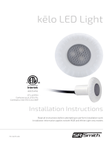
kēloXL LED Light
Installation Instructions
Read all instructions before attempting to perform installation work
Installation information applies to both RGB and White Light only models
4005496
ETL LISTED
Conforms to UL STD 676
Certied to CSA STD C22.2 #89
79-15283-00

2
Contents
OVERALL DIMENSIONS................................................ 3
FCC DECLARATION OF CONFORMITY .............................. 4
IMPORTANT INSTALLATION INFORMATION ........................ 4
INSTALLATION INSTRUCTIONS....................................... 5
BASIC OPERATION ..................................................... 7
THERMAL PROTECTION............................................... 7
WINTERIZATION ....................................................... 8

3
Thank you for purchasing the S.R. Smith kēloXL, 10” class LED Light for underwater retrot
wet-niche lighting applications. This light should t applications where the niche retaining
tab slot-to-pilot screw span is within 9.10” to 9.50” (up to 9.65” in certain niche conditions).
Will not t Swimquip niche applications.
NOTE – Niche must be in good condition and have the appropriate pilot screw for the niche.
This lighting product does not require bonding nor does it provide a bonding provision so if niche
bonding is required, the niche must have a separate bonding mechanism.
Install with large niches with similar mounting dimensions to model numbers:
• Jandy: PLNICLRG, PLNICVFLRG, SSNICLRG1R
• Pentair: 620004, 78210200 thru 700,
78210401, 79206700
• Hayward: SP0600U
• Sta-Rite: 05161-2352 thru 2369,
05163-2395 thru 2396
ELECTRICAL SPECIFICATIONS
Input voltage: 12VAC
Color Change (RGB): 38 Watts max
White Only: 42 Watts max
Color control through power
toggle triggers only.
Not compatible with S.R.Smith
PLX-PRM Controller
INPUT VOLTAGE RANGE
(based on S.R.Smith
PLX-PW,PL 60W or 100W
LV power unit - assumes
120VAC input line voltage)
CORD LENGTH STARTING VOLTAGE SETTING
up to 80' 12VAC
up to 150' 13VAC
150' + 3rd party unit 14-15VAC

4
This device complies with Part 15 of the FCC Rules. Operation is subject to the following two conditions:
(1) this device may not cause harmful interference, and
(2) this device must accept any interference received, including interference
that may cause undesired operation.
FCC WARNING
NOTE: Changes or modications of this product not expressly approved by the party responsible for
compliance could void the user’s authority to operate the equipment.
NOTE: This equipment has been tested and found to comply with the limits for a Class B digital device,
pursuant to Part 15 of the FCC Rules. These limits are designed to provide reasonable protection
against harmful interference in a residential installation. This equipment generates, uses and can
radiate radio frequency energy and, if not installed and used in accordance with the instructions,
may cause harmful interference to radio communications. However, there is no guarantee that
interference will not occur in a particular installation.
If this equipment does cause harmful interference to radio or television reception, which can be
determined by turning the equipment off and on, the user is encouraged to try to correct the
interference by one or more of the following measures
• Reorient or relocate the receiving antenna.
• Increase the separation between the equipment and receiver.
• Connect the equipment into an outlet on a circuit different from that to
which the receiver is connected.
• Consult the dealer or an experienced radio/TV technician for help.
IMPORTANT
FCC DECLARATION OF CONFORMITY
1. Ensure that the electrical system for your pool conforms with all requirements of the
National Electrical Code (NEC) and all relevant local codes and ordinances.
2. This 12V Underwater Light must be installed in accordance with the National Electrical
Code by a Certied Electrician or a Qualied Pool Technician.
NOTE: No Bonding to the light is required as the xture is all plastic construction and
complies with NEC article 680 Requirements.
3. Waterproof conduit must be present and in good working order from the niche to the
‘above ground’ junction box or power supply equipment listed for the application.
4. For supply connection, use only an isolating low voltage power supply with ungrounded
output, evaluated for swimming pool use. Raccorder uniquement à une alimentation
convenant à des luminaires submersibles.
5. DO NOT CONNECT THIS 12V LIGHT DIRECTLY TO A 120VAC CIRCUIT - LIGHT WILL
BE DAMAGED.
6. Install your S.R. Smith kēloXL LED Light/s as outlined in the following detailed instructions.
THIS DEVICE IS NOT INTENDED FOR USE WITH EMERGENCY EXITS
NE CONVIENT PAS AUX SORTIESDE SECOURS

5
INSTALLATION INSTRUCTIONS
Installation instructions for S.R.Smith kēloXL 10” class LED series to common/existing
wet-niche applications for concrete, berglass, and vinyl liner pools or spas
1. Make sure that all electrical circuits and connections related to the light install are de-energized
and rendered safe.
2. Per NEC Article 680.23 (5) - Lights are to be installed in no less than 18” (450mm) below the
normal water level unless the luminaire is listed and identied for use at lesser depths. S.R. Smith S.R. Smith
lights are listed and identied for use at depths no less than 4” (100mm) below the normal water lights are listed and identied for use at depths no less than 4” (100mm) below the normal water
level.level. All depth measurements are from the normal water level to the top of the Luminaire lens.
Existing niches should be located to meet these minimums. See Figure A for additional details.
3. While a wet removal of the existing niche light is possible, it is not recommended to be attempted
by inexperienced installers. S.R.Smith recommends that the water level be dropped to make the
installation as easy as possible.
4. Locate the conduit on the equipment side for the light’s low voltage cable (including the junction
box if applicable) and ensure that a pull line is run to pull the light cable through from the pool side.
5. Attach the pull line to the end of the kēloXL power cable with several wraps of electrical tape or
best method to aid in pulling the power cable through the conduit. Gently but rmly pull the cable
through the conduit to the equipment or junction box if applicable. DO NOT use excessive force
as the cord may be damaged during the pull. Depending on the layout and internal structure of
the conduit, water-based conduit lubricant may be required to enable an easier cord pull.
6. Pull the cord through the conduit to the desired location leaving 2-3 feet (or more if the depth at
the niche location is deeper) of slack at the pool niche end. While the kēloXL is not a serviceable
light, leaving the slack coiled in the niche will provide exible access for accessory items, such as
alternate trim plates or replacement slot tab parts. It may also help with winterization depending
on the installer’s preferred method.
7. Locate and unscrew the niche pilot screw and keep it on hand.
8. Locate the tab slot in the niche at the 6 o’ clock position and position the tab on the kēloXL to t in
that slot. In some cases, on concrete pools, the slot may be a bit too deep relative to the nished
surface of the pool wall. The screw holding the tab on the kēloXL may be unscrewed up to 2.5
turns max to allow for this variance. If more depth is needed, an alternate accessory tab part may
be required for installation.
9. Once the tab is placed in the niche slot at the 6 o’ clock position, locate the niche’s pilot screw
hole through the pilot screw slot on the kēloXL. Use the existing pilot screw to secure the kēloXL
to the pool niche. DO NOT over tighten the screw, it only needs to be snug against the wall and
further tightening will not make it more secure.
10. Connect the red / black wire conductors of the S.R.Smith kēloXL to an approved, low voltage, Class
2, Magnetic Isolation type transformer that complies with UL379 or an S.R.Smith *poolLUX™
branded power unit operating between 12 - 14VAC (rated @ 50W per light) as required by NEC or
relevant local codes. As the operation is Low Voltage AC power, there is no polarity requirement.
11. The kēloXL is now ready for use and will operate similar to most of the other S.R.Smith LED lights.
See the next section for operation of your new kēloXL.

6
Fig A. Water depth illustration - kēloXL prole
Luminaire is listed and identied for use at 4” or more below the normal
water level of the pool.

7
BASIC OPERATION
When connected to an approved, 12VAC, Class 2 power supply - The S.R.Smith kēloXL LED color
changing light uses simple ‘off / on’ power switching to control the basic, pre-dened color modes
with memory function.
MEMORY
The memory function remembers the last color
setting. For example, if the light was last used in
the blue mode, the next time the light is turned on
it will be blue mode.
COLOR MODE SELECTION
The LED will turn on to the color in memory. To
move to the next color mode, quickly (within one
second or faster) toggle the power to the lights
’OFF / ON’.
Advance through the modes until the desired mode
is selected. The modes will cycle 1,2,3,4,5,6,7,8,
then cycle back to 1. See table below for details.
COLOR SYNC RESET
To synchronize all lights on the system including older *Fiberstars LED Series Pool lights, you
must use the following sequence:
1. Turn lights ‘ON’ to conrm the color modes are out of sync.
2. Turn lights ’OFF’ for 5 seconds or more.
3. Toggles lights ’ON’ / OFF’ three times within three seconds - must end in ’OFF’ condition
4. Leave lights in ’OFF’ condition for 5 seconds.
5. Turn lights ‘ON’ and conrm that all lights are in mode #1, Soft Color Change
FOR LED COLOR CHANGING MODELS (RGB)
WHITE ONLY LAMPS ARE SIMPLY ON OR OFF
COLOR MODE SELECTION GUIDE
Mode 1 Soft Color Change
Mode 2 White
Mode 3 Blue
Mode 4 Green
Mode 5 Red
Mode 6 Amber
Mode 7 Magenta
Mode 8 Flash Color Change
*Older Fiberstars LED lights can synchronize with the newest generation lights
ONLY if they have their DIP switches in their default, ’All Down’ position. In a mixed
environment, the Color Sync Reset will need to be performed each time the lights
are used, and color synchronization is desired.

S.R.Smith, LLC
800.824.4387
srsmith.com
© 2021 S.R.Smith, LLC All rights reserved. 79-15283-00 1221 B
Questions?
Contact One of Our Dedicated Lighting Specialists. 1-800-824-4387 x4012 or x2282
WINTERIZATION RECOMMENDATIONS
Swimming Pools may or may not be drained completely. If not drained completely, the water
level should be lowered below the S.R.Smith kēloXL / niche location and make sure that all
water is drained from the niche and conduit if applicable. The kēloXL may be disengaged from
the niche and brought up to the deck and secured under a sturdy covering for the winter period.
Alternatively, the kēloXL may be disengaged as before but if enough cord has been left in the
niche, the light may be sunk to the bottom of the pool during the winter season. Weights may be
needed to hold it place.
NOTE - If water is trapped in the conduit, damage may occur from freeze expansion.
THERMAL PROTECTION
This sealed light is equipped with thermal protection circuitry. If the circuit detects that the
light is getting too hot for a given environment, it will automatically reduce the brightness in
increments until the light reaches a safe thermal threshold. If this condition occurs, it may or may
not be noticeable by the human eye and is a normal operating function, not a sign of malfunction
or failure.
/
