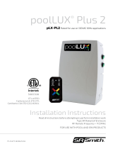
S.R.Smith PT-6001 and PT-6002 Fiber to LED Conversion Kit Installation guide

Type
Installation guide
PT-6001 Power Tower
Installation Instructions

FOR USE WITH POOL AND SPA PRODUCTS
79-15280-00 08/19 Rev.A0
4008814
ETL LISTED


2
3
Contents
IMPORTANT SAFETY INFORMATION .....................4
FCC WARNING ........................................4
SPECIFICATIONS .......................................5
INSTALLATION GUIDELINES .............................6
 ............9
 ..........9
ELECTRICAL PROTECTION MEASURES ..................10
WIRELESS REMOTE OPERATION .......................11
 ..................................12
4
IMPORTANT SAFETY INFORMATION


1. 
2. 
COPPER CONDUCTORS.
 

4. 

5. 

 
FCC WARNING
1. 


2. 

ELECTRICAL SHOCK HAZARD – SWITCH DOES NOT TURN OFF INPUT POWER.



DANGER – FAILURE TO FOLLOW THESE WARNINGS, INSTRUCTIONS, AND THE
OWNER’S MANUAL MAY RESULT IN SERIOUS INJURY OR DEATH.
ELECTRICAL RATINGS



5
SPECIFICATIONS
ELECTRICAL RATINGS



CONSTRUCTION




Maximum Soil Height:
Do NOT allow fill to
exceed this level
Optional PT-BASE for
new installations or when
previous 2000/6000
Series illuminator base is
not available.
CAUTION: THE EQUIPMENT AND
CONTROLS SHALL BE LOCATED NOT
LESS THAN 1 M HORIZONTALLY
FROM THE SPA OR HOT TUB
ATTENTION: MAINTENIR UNE
DISTANCE MINIMALE, MESURÉE
DANS UN PLAN HORIZONTAL, DE 1 M
ENTRE LA CUVE DE RELAXATION ET
LES APPAREILS ET COMMANDES
6





1. Figure A
 
Figure A

 
Figure A

INSTALLATION GUIDELINES
Low Voltage
Terminals
12VAC Conduit Hole: At Least
12" of Free 12VAC Cord Should
Be Protruding Past Hole
Electrical Conduit Hole:
Electric Conduit Should
Protrude1" Or Less
Use Sweep Ells Or Heat
Bend For Gentle Radius
60W Transformer
(behind bracket)
Fuse location
w/ 6A Fuse
High Voltage
Terminals
RF Receiver & Antenna
Overview of internal component loca ons
FIGURE A: Op onal part PT-BASE
7
Connect 120VAC power INPUT wiring to the unit’s 3-wire cage clamp.
1. 


2. 
 
4. 

5. 
 
 
 
 Figure B
 
 
 
 
 
7. Figure C.
8. 
A en on – Do Not Lose the provided Installa on Tool, it is required for removal of the input wires should
service or replacement be required.
FIGURE B (Steps 6a-6e): Installa on tool use – Insert fully, lever towards
the le , insert wire, release tension by moving tool to the right, remove
tool, & pull test wire
FIGURE C (Steps 7 & 8): Cage clamp shown with 120VAC
input wires in place (connected and dressed, right side)
8
12V Power Output Terminals

Figure D



Do not exceed 60W load.

1. 

2. 
 
4. 
Figure E

5. 

 

7. Figure F
12V or 13V AC Low voltage accommodations






Figure G
FIGURE D: Low Voltage Output
connecon terminal
FIGURE E: Lever terminal in open posion
FIGURE F: Low voltage light cord shown
connected
FIGURE G: Red-Blue or
Red-Yellow wires used for 12V
or 13V output.
9
STAND-ALONE ENVIRONMENT & OPERATION
INSTALLING THE PT-6001 UNIT TO THE PT-BASE
TOGGLE SWITCH OPERATION


Manual Operation


Remote On/Off Operation



1. 

2. 
 
4. 
5. 

ON

OFF

REMOTE
10
ELECTRICAL PROTECTION MEASURES

1. 


2. 



11
WIRELESS REMOTE OPERATION





Note:

Sleep Mode






To Turn On Using the Wireless Remote Operation


Color Changing Operation



NEW FEATURE
1-Button - Color Sync / Reset Operation






Performance Note:


PAIRING CODE CHART
DIP Switch 1 2 3 4
OFF OFF OFF OFF
 ON OFF OFF OFF
 OFF ON OFF OFF
 ON ON OFF OFF
 OFF OFF ON OFF
 ON OFF ON OFF
 OFF ON ON OFF
 ON ON ON OFF
 OFF OFF OFF ON
ON OFF OFF ON
 OFF ON OFF ON
 ON ON OFF ON
 OFF OFF ON ON
 ON OFF ON ON
 OFF ON ON ON
 ON ON ON ON
12
WARRANTY INFORMATION




srsmith.com

Questions?
 1-800-824-4387 
www.srsmith.com.
TROUBLESHOOTING







1. 
2. 
 


4. 




5. 



 

  • Page 1 1
  • Page 2 2
  • Page 3 3
  • Page 4 4
  • Page 5 5
  • Page 6 6
  • Page 7 7
  • Page 8 8
  • Page 9 9
  • Page 10 10
  • Page 11 11
  • Page 12 12

S.R.Smith PT-6001 and PT-6002 Fiber to LED Conversion Kit Installation guide

Type
Installation guide

Ask a question and I''ll find the answer in the document

Finding information in a document is now easier with AI