Page is loading ...

poolLUX® Premier
pLX-PRM Rated for use on 120VAC 60Hz applications
Installation Instructions
Read all instructions before attempting to perform installation work
Type 3R Rainproof Enclosure
RF Remote Frequency = 915MHz
FOR OUTDOOR USE ONLY WITH S.R.Smith poolLUX® ACP COMPATIBLE POOL,
SPA, and WATER FEATURE LIGHTING PRODUCTS
5000004
ETL LISTED
Conforms to UL STD 379;
Certied to CSA STD C22.2 #218.1
79-15263-00 REV4/18
LED Lighting Controller for White and Color
Changing poolLUX® Advanced Control Protocol
(ACP) compatible light sources

2
Contents
IMPORTANT SAFETY INFORMATION ................................3
RF Exposure Statement .................................................4
IC Statement.............................................................4
FCC WARNING .........................................................4
Electrical Ratings ........................................................5
Recommended Tools and Supplies ......................................5
INSTALLATION INSTRUCTIONS.......................................6
Enclosure mounting .....................................................6
Input / Supply Line Voltage ..............................................7
Optional wiring for external relay control...............................7
Output wiring to poolLUX® ACP compatible light sources..............8
RF Remote Control Pairing..............................................9
OPERATING INSTRUCTIONS........................................ 10
Control Box Operation ................................................ 10
RF Remote Control Operation ........................................ 11
THE POOLLUX® PREMIER LAYOUT ................................. 12

3
IMPORTANT SAFETY INFORMATION
CAUTION: POWER AND SIGNAL OUTPUT CONDUITS MUST BE NON-METALLIC
ATTENTION: CONDUITS POUR PUISSANCE DE SORTIE ET SORTIE SIGNAL DOIT ETRE NON METALLIQUE
ELECTRICAL SHOCK HAZARD – SWITCH DOES NOT TURN OFF INPUT POWER.
Failure to disconnect input power before servicing can lead to serious injury, or death.
Disconnect input power before servicing.
Replace all parts and panels before reconnecting power and operating
DANGER – FAILURE TO FOLLOW THESE WARNINGS, INSTRUCTIONS, AND THE
OWNER’S MANUAL MAY RESULT IN SERIOUS INJURY OR DEATH.
Basic safety precautions shall be observed when installing and operating the poolLUX® Premier
(Part Number pLX-PRM) and other associated equipment:
1. A qualied electrician must install the poolLUX® Premier in accordance with the NEC ANSI/
NFPA 70 and Article 680 requirements.
2. For proper operation, the poolLUX® Premier must be mounted on a vertical wall, planar, or
vertical surface oriented with the conduit openings at the bottom. The enclosure must be
not less than 4 inches above the ground level, pool deck, or not less than 8 inches above the
maximum pool water level, whichever provides the greater elevation. Unit must be positioned
not less than 4 feet (1.2 m) from the inside wall of the pool unless separated from the pool by a
solid fence, wall, or other permanent barrier.
3. ONLY USE COPPER CONDUCTORS.
4. Do not exceed the maximum ratings of individual output channels, components, wiring
devices, and current carrying capacity of conductors.
5. The FLED Series Underwater Luminaires and CLS-2is are water feature light sources
intended for use with this controller and are Article 680 of the National Electrical Code
compliant and do not need to be bonded due to their polymeric or isolated application design.
6. This device should never operate equipment that could cause property damage, bodily injury,
or death should it be activated unexpectedly.
7. Use with branch circuit breakers with 15 amperes or less.
8. Must be used with an approved ground-fault circuit interrupter (GFCI).
9. Use rain-tight or wet location hubs that comply with the requirements in the standard for
conduit, tubing, and cable ttings (UL514b) only.
10. The conduit hub is to be connected to the power input conduit before the hub is connected to
the enclosure.
11. Never allow children to operate the poolLUX® Premier unsupervised.

4
RF Exposure Statement
IC Statement
FCC WARNING
To maintain compliance with FCC’s RF Exposure guidelines, this equipment should be installed
and operated with minimum distance of 20cm between the radiator and your body. Only use the
supplied antenna.
This device complies with Industry Canada license-exempt RSS standard(s). Operation is subject to
the following two conditions:
(1) this device may not cause interference, and (2) this device must accept any interference,
including interference that may cause undesired operation of the device.
Le présentappareilestconforme aux CNR d’Industrie Canada applicables aux appareils radio
exempts de licence. L’exploitationestautorisée aux deux conditions suivantes:
(1) l’appareil ne doit pas produire de brouillage, et (2) l’utilisateur de l’appareildoit accepter
tout brouillageradioélectriquesubi, mêmesi le brouillageest susceptible d’encompromettre le
fonctionnement.
1. This device complies with Part 15 of the FCC Rules. Operation is subject to the following two
conditions: (1) this device may not cause harmful interference, and (2) this device must accept
any interference received, including interference that may cause undesired operation.
2. Changes or modications not expressly approved by S.R.Smith, LLC will void the user’s
authority to operate the equipment.
NOTE: This equipment has been tested and found to comply with the limits for a Class B digital
device, pursuant to Part 15 of the FCC Rules. These limits are designed to provide reasonable
protection against harmful interference in a residential installation. This equipment generates,
uses and can radiate radio frequency energy and, if not installed and used in accordance with
the instructions, may cause harmful interference to radio communications. However, there is no
guarantee that interference will not occur in a particular installation. If this equipment causes
harmful interference to radio or television reception, which can be determined by turning the
equipment off and on, the user is encouraged to try to correct the interference by one or more of
the following measures:
• Reorient or relocate the receiving antenna.
• Increase the separation between the equipment and receiver.
• Connect the equipment on a different circuit than that of the receiver.
• Consult the dealer or an experienced Radio and Television Technician for help.

5
Electrical Ratings
Do not exceed the maximum electrical output rating of each unit listed below.
Input
100 - 120VAC 50/60Hz, 2A max.
For safety reasons, a GFCI protected circuit must be used to power the poolLUX® Premier.
• Connect the GFCI load Hot to the poolLUX® Premier Hot input terminal.
• Connect the GFCI load Neutral to the poolLUX® Premier Neutral input terminal.
• Connect the Earth ground (Green) from the GFCI Ground line to the Ground line of the
poolLUX® Premier.
Output
Each of the poolLUX® Premier output channels is rated up to 0.58A @ 12VAC rms. or 7W max.
Do not exceed the maximum electrical rating of 70W (7W x 10 ports = 70W combined output)
for the combined individual output ports on the poolLUX® Premier.
Only use with S.R.Smith poolLUX® ACP compatible LED lights and water features.
Thermal Cutoff
The poolLUX® Premier will take self-preservation measures during operation and will shut down if
the unit overheats. During this shutdown, the poolLUX® Premier will behave in the following manner:
• The lights will be turned off
• The “OH” will be displayed on the front panel.
• The RF Remote and the front panel buttons will be disabled.
Once normal operating temperatures have been reached, the unit will shift into recovery mode
and display “OF.” The lights will remain off until activated via the RF Remote or the manual front
panel buttons.
Recommended Tools and Supplies
1. Circular hole saw/s for installation of 3/4” and/or 1” non-metallic conduit. (No spade bits)
2. Application appropriate and approved ‘rain-tight’ or ‘wet location’ conduit hubs.
3. Extra Duct Seal for high count, multi conduit installations.
* Note: It is recommended to hand tighten all screw terminals and screw fasteners inside the
enclosure and front cover until snug and secure. Be sure not to overtighten as permanent
damage may occur.

6
INSTALLATION INSTRUCTIONS
WARNING
• TURN OFF INCOMING POWER BEFORE SERVICING EQUIPMENT.
• ALL INSTALLATION AND MAINTENANCE WORK MUST BE PERFORMED BY QUALIFIED
ELECTRICAL PERSONNEL ONLY.
• VERIFY ALL ELECTRICAL RATINGS BEFORE INSTALLATION IS COMPLETE.
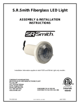
Enclosure Mounting
1. Locate the poolLUX® Premier on a wall in an appropriate area for a swimming pool light
controller or low voltage power source as referenced in #2 of the “Important Safety
Information” section on page 3.
2. The power input and output conduits need to be run separate to this location.
3. Allow for enough room on the wall surface that only the stand-off mounting tabs will contact
the wall and that a minimum of 9/32” (7.2mm) air gap is maintained between the back of the
unit and the wall. Using the four mounting tabs on the corners of the enclosure, mark and drill
holes for #10 screws.
4. Mount the poolLUX® Premier enclosure securely to the wall, using the screw locations.
WALL
Minimum Gap of 9/32" or 7.2mm

7
Input / Supply Line Voltage
1. Open the enclosure by unscrewing the six (6) panel cover screws with a straight blade
screwdriver; DO NOT USE A POWER DRIVER.
2. Open the cover and support it. DO NOT LET IT HANG BY THE ATTACHED CABLES.
3. Carefully detach the ribbon cable by gently pulling it from the connector straight out from
the PC board.
4. Place cover panel in a safe area to avoid damage.
5. Loosen and remove the metal “Isolation Barrier” mounting screw on the right side of the barrier
plate. Once unscrewed, the plate will pull straight out to allow easier access to the conduit
knockout locations. *Note – Once all conduits are connected, replace the barrier plate and
reattach with the removed mounting screw from the right side. Hand tighten until secure.
6. Bring supply power conduit to the front (preferred) or back left input power conduit knockout.
No output connections are allowed through these locations.
7. Open the knockout location with a hole saw (depending on conduit hub size) for use with ¾” or
1” conduit.
8. Attach an approved ‘rain-tight’ or ‘wet location’ hub to the conduit rst, then attach hub to
the enclosure.
9. Bring the GFCI protected, 15A max, supply voltage to the supply line voltage wiring board on
the left side of the unit. The clear plastic input wiring terminal cover will need to be snapped out
and removed in order to connect to the Hot, Neutral, and Ground terminals. Once the power
input connections are secure, replace the terminal cover to prevent accidental contact.
Optional Wiring for External Relay Control
1. The poolLUX® Premier allows for standard (off/on) color mode control through a 3rd party,
external controller. By connecting the two ‘relay’ terminals to a ‘dry contactor’ relay (or switch)
on an external controller, the poolLUX® Premier will advance the color one mode at a time
when the dry contactor is closed and opened once within 1.5 seconds.
2. A “soft off” mode can be enabled by a close and latching of the terminal contacts for more than
1.5 seconds. Operation will resume when terminals are unlatched for more than 2 seconds at
the same brightness and color.

8
Output Wiring to poolLUX® ACP-Compatible Light Sources:
1. The poolLUX® Premier supports ten (10), 7W output circuits. Each circuit can power one (1)
kelo (KLED-C or KLED-W), or one (1) Treo (FLED-C-TR or FLED-W-TR), or one (1) Fiberglass
(FLED-C-FG or FLED-W-FG), or one (1) CLS-2is water feature. The ports can also support up
to three (3) Treo Micro (FLED-TM-C or FLED-TM-W). The singular or cumulative light load
must never exceed the 7W port capacity.
2. The enclosure provides six (6) output conduit locations. If additional conduit terminations are
required, an approved junction box may be used as a termination point and multiple output
cables may be run through a single feeder conduit to the poolLUX® Premier.
3. Open the necessary output knockout locations with a hole saw for use with ¾” or 1” conduit.
4. Bring output conduits to the knockout locations opened in the previous step. Any conduit used
as output wiring runs between the lights and poolLUX® Premier and any external controller
shall be Non-Metallic (polymeric).
ATTENTION : LES CONDUITS DOIVENT ÊTRE RELIÉS PAR LA MASSE
5. Attach an approved ‘Rain-tight’ or ‘wet location’ hub to the conduit rst, and then attach hub to
the enclosure. Once all conduits are connected, replace the barrier plate and reattach with the
mounting screw from the right side.
Tighten to 15 in/lbs.
6. Install the poolLUX® ACP compatible lights as per instructions with the low voltage wiring
pulled to the poolLUX® Premier and trimmed to length, leave 24 to 36 inches of slack for future
service work. Each light will need to have each of its conductors stripped back approx. ¼”.
7. Securely connect each light’s two conductor cord to an empty output channel screw terminal
location. It does not make a difference which wire is assigned to the channel’s terminal as long
as both wires ll the output position and are not bridged to an adjacent channel. Hand tighten
all terminal screws until snug and secure.
8. Once all lights are securely connected, use a small quantity of the included Duct Seal material
(grey putty) around the cables to seal the conduits and prevent circulation of air between the
conduits and the enclosure.
9. After the conduits are sealed, do a nal inspection for potential wiring issues to correct. Once
inspected, prepare the cover panel for reattachment. Conrm orientation of the ribbon cable’s
key guide and gently insert the connector until seated; do not rock the connector side to side.
10. Align cover panel over the enclosure opening and evenly screw down the six (6) screws until
snug and gasket makes good contact all around with enclosure.
DO NOT USE A POWER DRIVER.
11. Energize the input supply voltage.
12. Turn on the power switch of poolLUX® Premier. Once the unit completes the power-on cycle,
the digital display will display “OK” if everything is connected correctly.

9
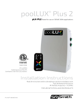
RF Remote Control Pairing
The RF remote control must rst be paired to the poolLUX® Premier before it can be used properly.
Number Descriptions
1 Color Mode Button
2 Dimming and RF Pairing Button
Pairing Process:
• Press and hold the color mode button (Number 1) on the RF remote for more than 3 seconds to
begin the pairing process. The LED display will display “RF” showing pairing is in progress.
• Press and hold the dimming and RF pairing button (Number 2) on the poolLUX® Premier until the
‘RF’ symbol disappears indicating the remote is now paired.
2
1

10
OPERATING INSTRUCTIONS
Control Box Operation:
Number Descriptions
1 Power Switch
2 Digital Display
3 Color Mode Button
4 Dimming and
RF Pairing Button
The master power switch (number 1) will turn red when the poolLUX® Premier is on.
The display (number 2) will display the following:
Number Descriptions
ON On
OF Off (standby)
number 1 to 8 Mode number when the color mode is changed
number 0 to 15 Additional dimming levels
The color mode button (number 3) cycles through the 8 preprogrammed color modes:
Color Mode Selection Guide
Mode 1 Soft Color Change
Mode 2 White
Mode 3 Blue
Mode 4 Green
The dimming button (number 4) cycles the lights through the 15 dimming levels.
Level 15 = full output, Level 0 = off.
4
3
2
1
Mode 5 Red
Mode 6 Amber
Mode 7 Magenta
Mode 8 Party Mode

11
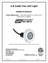
RF Remote Control Operation:
Number Descriptions
1 Power Button
2 Color Mode Button
3 Color Ring
4 Dimming Bar
Pressing the red power button (number 1) on the
remote will turn the lights on and off. When the lights
are in the off state the LED display will show ‘OF’ (off).
*Note: The remote control will go into sleep mode
when it has not been used in 30 seconds. Wake the
remote by pressing the power button (number 1)
on the remote control once before resuming
normal operation.
The color mode button (number 2) cycles through 6
predened colors and 2 lighting shows:
Color Mode Selection Guide
Mode 1 Soft Color Change
Mode 2 White
Mode 3 Blue
Mode 4 Green
The color ring (number 3) is used to adjust the color of the lights by touching the desired color on
the ring. White light can be selected by touching the center dot in the middle of the color ring.
The dimming bar (number 4) at the bottom of the remote control allows for a person to control the
brightness of the lights from 0 to 100%.
• Sliding a nger from the left end to the right end of the bar will increase the brightness of the
lights in 25% increments to 100% brightness.
• Sliding a nger from the right end to left end of the bar will decrease the brightness of the lights in
25% increments to “Off”.
*Note: Finer control of dimming (15 levels) can be accessed directly on the front panel of the
poolLUX® Premier control box - see page 10.
*Please Note: The remote control is highly water resistant. It will oat if accidently dropped in
water. It is not recommended to let the remote control oat or be submerged under water for any
length of time as it is not waterproof.
4
3
2
1
Mode 5 Red
Mode 6 Amber
Mode 7 Magenta
Mode 8 Party Mode

12
THE POOLLUX® PREMIER LAYOUT
Number Descriptions
1 Power Switch
2 Digital Display
3 Color Mode Button
4 Dimming and RF
Pairing Button
5 LED Light Cable Output
6 Input Power conduit
location (primary)
7 RF Remote Control
WARRANTY INFORMATION
For Lighting product warranty information and details, please visit our website:
www.srsmith.com/warranty
PRODUCT REGISTRATION
Register your PoolLUX® Premier lighting control to ensure
you receive important product information updates.
Scan the QR code to register now or visit srsmith.com.
S.R.Smith, LLC
P.O. Box 400 | Canby, OR 97013
P 503.266.2231 TF 800.824.4387
srsmith.com
79-15263-00 REV4/18
Questions?
Contact One of Our Dedicated Lighting Specialists. 1-800-824-4387 x4012 or x2282
4
3
5
2
1
6
© 2018 S.R.Smith. All rights reserved.
/